US1663184A - Railroad gate - Google Patents
Railroad gate Download PDFInfo
- Publication number
- US1663184A US1663184A US168361A US16836127A US1663184A US 1663184 A US1663184 A US 1663184A US 168361 A US168361 A US 168361A US 16836127 A US16836127 A US 16836127A US 1663184 A US1663184 A US 1663184A
- Authority
- US
- United States
- Prior art keywords
- gate
- train
- arms
- latch
- shaft
- Prior art date
- Legal status (The legal status is an assumption and is not a legal conclusion. Google has not performed a legal analysis and makes no representation as to the accuracy of the status listed.)
- Expired - Lifetime
Links
Images
Classifications
-
- B—PERFORMING OPERATIONS; TRANSPORTING
- B61—RAILWAYS
- B61L—GUIDING RAILWAY TRAFFIC; ENSURING THE SAFETY OF RAILWAY TRAFFIC
- B61L29/00—Safety means for rail/road crossing traffic
- B61L29/08—Operation of gates; Combined operation of gates and signals
- B61L29/18—Operation by approaching rail vehicle or rail vehicle train
- B61L29/22—Operation by approaching rail vehicle or rail vehicle train electrically
- B61L29/222—Operation by approaching rail vehicle or rail vehicle train electrically using conductor circuits with separate contacts or conductors
- B61L29/224—Operation by approaching rail vehicle or rail vehicle train electrically using conductor circuits with separate contacts or conductors using rail contacts
Definitions
- Figure 6 is a section on the 1ine'66 of Figure 5;
- V I i Figure 7 is a section on the line 77 of Figure 1
- Figure 8 is a sectional elevation showing the switch mechanism;
- Figure 9 is an elevation showing the train actuated portion of the means for latching the gates closed
- Figure 10 is a circuit diagram.
- the numeral 1 marks a railroad track.
- Outer barriers 2 and an intermediate barrier 3 are disposed transversely of the track 1.
- the barriers 2 and 3 define highways 1 crossing the track 1.
- Casings 5 are located by the barriers 2,. at any desired distance from the railroad track 1.
- Gate shafts 7 are located adjacent to the outer barriers 2 on both sides of the track 1.
- the gate shafts 7 carry horizontally swinging gates 8.
- the gates 8 close from the outer barriers 2, across the highways 4, and against the intermediate barrier 3, asshown' in dot and dashlines in Figure 1.
- Sleeves 9 are splined at 10 to the gate'sha'fts 7 to rotate therewith, and to slide thcrealong.
- the sleeves 9 are journaled in the upper The lower ends of parts of the casings 5.
- the-gate shafts 7 are journaled in the bearings 6.
- Torsion springs 18 surround the sleeves 9. Th'e'ends ofthe-torsion springs 18 are connected to thesleeves 9 andto the driving connection between vthe worms-l4;
- clutches may s1ip,-thereby to prevent the motors 16 from beingchoked back.
- V i iousings 19 are located along the track '1 on opposite sides of the highways i.
- Shafts 20 are supported for rotation in the .hOUS-g ings l9.
- Torsion springs 21 surround-the shafts, 20.
- -The'shafts 20 have upstanding arms 22'.
- Cross links 23 are pivoted intermediate their ends to'the arms 22.
- Thelinks 23 are pivoted at their ends to switch arms 24'whi'ch, at their lower ,ends are pivot-ally mounted-on the'housings 19. This is shownbest in Fig ure 8.
- the shafts v20 have arms 28 located externally ofjthehousingseu 19. The upper endsjof the arms 28 are pivotally connected with the intermediate portions of 'train actuatedmembers ;29, located along the track 1,. the" members 29 being pivoted to pivotally mounted supes ports 30.
- Main conductors 31'and 32 are shownin FigurelO.
- Conductors 33 are connected tothe conductors 31 andto'; the sivitchpoints 25 and 27.
- Conductors 34 connect the con-f doctor 32 with the switchpoints 26.
- One switch arm 24: of each pair is joined to the corresponding switch arm of the other vpair by a conductor 35 The remaining switch arms of each pair are joined by a conductor. 36.
- the reversing motors 16 are connected in parallel, as shown at137, with theconductors 35 and'36.
- Signals 38 such as bells'j or the like, are located adjacent to the high ways 1.
- the conductor 39 is connected at 40 to a looped conductor alwhichis joined to the conductorv 31.
- the switches- 11; are interposedinth'e conductor 41. 4 i q ;A shaft 4:2 is supported for-rotationa'sj" indicated at 50, and extends along theintermediate'ba'rrier'3.
- the shaft .42 is provided atone end with a latch 44 whichcooperates" with one of the gates 8 to hold it closed.
- a torsion spring-j43' is disposed-aboutfthe intermediate portion of the shaft 42.
- shaft 42 has an arm 45 which cooperates r the shaft 48 having a latch 49 adapted to ooby a passing train.
- Torsion springs 57 are operate with the other gate to hold it closed.
- a cross arm 51 is connected to the shaft 42.
- the inner ends of operating rods 52 are connected to the cross arm 51.
- the operating rods 52 extend in opposite directions along the trackl.
- One of the operating rods 52 has akeeper 53.
- the operating rods 52' are pivoted to arms 54 on shafts 55 journaled in casings 56 disposed along the track 1 on opposite sides of the highways 4.
- the arms 54 are so located that they may be engaged connected to the shafts 55 and are located in the casings 56.
- latch 58 is pivotally mounted intermediate its ends, as at 59, and is located at the intersection of the railroad track and the highway. One end of the latch 58 isbeveled at 60 for cooperation with the keeper 53. The other end 61 of the latch 58 is adapted to be engaged by a passing train.
- Vertical shafts 62 are journaled in the outer barrier's'3. Shafts 62 are under the control of torsion springs 63. The shafts 62 are provided-at their upper ends with beveled latch arms 64 adapted to cooperate automatically with the gates 8 to hold the gates closed, when the gates are controlled by an operation as hereinafter explained.
- the shafts 62 are supplied at their lower ends with arms 65 pivoted to rods 66.
- Pitmen 67 are pivoted to the rods 66 and are pivoted at 68 to operating members or treadles 69 which are pivotally mounted at 70 for vertical swinging movement,-'at the outer ends of the barriers 2-3, the treadles 69 being located on opposite sides of the railroad track 1.
- the sleeves 9 on the gate shafts are provided near to their lower ends with -arms'71 united with connecting rods 72, pivotally, the rods 72 having a lost motion: pivotal connection at 73 with hand levers 74 located near to the outer ends of the barriers 2 on oppositesides of the track 1, the hand levers 74 being pivotally mountwith the beveled end 60 of the latch 58.
- the train having cleared the highway crossing, arrives at the left hand end of Fig-' ure 10, and the corresponding train-actuated member 29 is operated, motion being transmitted to the switch arms 24 at the left end of Figure 10, these switch members closing on the points 25 and 26 and the motors 16 being reversely operated.
- the worms 14 move the gears 12 clockwise toward the position shown in Figure 6, and one of the first things that take place is that the switch members no longer are engaged by the gear 12, but are opened, the signals 88 being made to cease their operation.
- the gears 12 turn the sleeves 9 and the shafts 7 clockwise, by means of the clutch elements 76, and the springs 18 are put under torsion.
- the gates 8 are opened, but when they are opened they do not swing into contact with the latch arms 64 of Figure 1.
- the device may be operated eventhough the train control becomes inoperative due to the stripping or breaking of the clutch 76 and gear 18: for, in such an event, a person in a vehicle can tilt the hand lever 7 4, operate the rod 72, rotate the shaft 7 by way of the arm 71 ( Figure 5), the sleeve 9, and the spline 10, the gate engaging automatically with the latch arm 64;.
- the gate thus, is held open until the vehicle which is traversing the highway moves over the correspond ing treadle 69: whereupon the pitman 67, the
- the combination with a track and a highway crossing, of a movable highway gate means actuated by a train on the track for opening and closing the gate; means for holding the gate releasablyopen, said means comprising a shaft supported for rotation and extended along the highway, aslidable member connected to the shaft eccentrically of the shaft, a keeper on the slidable member, a latch movably supported adjacent to the track and comprising apart wherewith the latch automatically engages to hold the gate closed when the slidable member is moved in one direction, train-actuated means for moving the slidable member in said direction, a portion of the latch being engageable by a train to release the latch from the keeper and to permit a movement of the slidable member in the opposite direction, and an opening of the gate, and means for moving the slidable member in the last-speoificd direction.
Description
March 20, 192s. 1,663,184
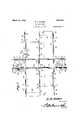
R. D. STOKES RAILROAD GATE Filed Feb. is. 1927 2 Sheets$h eet 1 12 2. Shires vvvewtoz March 20, 1928.
R. D. STO KES RAILROAD GATE Filed Feb. 15. 1927 2 Sheets-Sheet 2 Patented Mar. 29, 1928., V
ROBERT D. STOKES, or enigma, VIRGINIA.
RAILROAD GATE.
Application filed February 15.1927. Serial in. 168,361.
Figure 6 is a section on the 1ine'66 of Figure 5; V I i Figure 7 is a section on the line 77 of Figure 1 Figure 8 is a sectional elevation showing the switch mechanism; v
Figure 9 is an elevation showing the train actuated portion of the means for latching the gates closed;
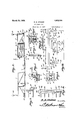
Figure 10 is a circuit diagram.
The numeral 1 marks a railroad track. Outer barriers 2 and an intermediate barrier 3 are disposed transversely of the track 1. The barriers 2 and 3 define highways 1 crossing the track 1. Casings 5 are located by the barriers 2,. at any desired distance from the railroad track 1. There are bearings 6 in the bottoms of the casings 5. Gate shafts 7 are located adjacent to the outer barriers 2 on both sides of the track 1. The gate shafts 7 carry horizontally swinging gates 8. The gates 8close from the outer barriers 2, across the highways 4, and against the intermediate barrier 3, asshown' in dot and dashlines in Figure 1. Sleeves 9 are splined at 10 to the gate'sha'fts 7 to rotate therewith, and to slide thcrealong.
The sleeves 9 are journaled in the upper The lower ends of parts of the casings 5. the-gate shafts 7 are journaled in the bearings 6. Torsion springs 18 surround the sleeves 9. Th'e'ends ofthe-torsion springs 18 are connected to thesleeves 9 andto the driving connection between vthe worms-l4;
and thegears 12, but when the movement on of the -gears 12 is stoppedv forcibly, the
clutches may s1ip,-thereby to prevent the motors 16 from beingchoked back. unduly, and becomingoverheated, V i iousings 19 are located along the track '1 on opposite sides of the highways i. Shafts 20 are supported for rotation in the .hOUS-g ings l9. Torsion springs 21 surround-the shafts, 20. -The'shafts 20 have upstanding arms 22'. The torsion-springs 21-are con-97o nected to thehousings 19'21I1dji30 the arms 22. Cross links 23 are pivoted intermediate their ends to'the arms 22. Thelinks 23 are pivoted at their ends to switch arms 24'whi'ch, at their lower ,ends are pivot-ally mounted-on the'housings 19. This is shownbest in Fig ure 8. The switch. arms 24:.are adapted. to. cooperate with switch points 25', 26fand 27 on the housings '19. The shafts v20have arms 28 located externally ofjthehousingseu 19. The upper endsjof the arms 28 are pivotally connected with the intermediate portions of 'train actuatedmembers ;29, located along the track 1,. the" members 29 being pivoted to pivotally mounted supes ports 30. V
. Main conductors 31'and 32 are shownin FigurelO. Conductors 33 are connected tothe conductors 31 andto'; the sivitchpoints 25 and 27. Conductors 34: connect the con-f doctor 32 with the switchpoints 26. One switch arm 24: of each pair is joined to the corresponding switch arm of the other vpair by a conductor 35 The remaining switch arms of each pair are joined by a conductor. 36. The reversing motors 16 are connected in parallel, as shown at137, with theconductors 35 and'36. Signals 38, such as bells'j or the like, are located adjacent to the high ways 1. The signals 38 'areinterposed ina conductor 39, that is joined to the condu'oi tor 32. The conductor 39 is connected at 40 to a looped conductor alwhichis joined to the conductorv 31. The switches- 11; are interposedinth'e conductor 41. 4 i q ;A shaft 4:2 is supported for-rotationa'sj" indicated at 50, and extends along theintermediate'ba'rrier'3. The shaft .42is provided atone end with a latch 44 whichcooperates" with one of the gates 8 to hold it closed. 110 A torsion spring-j43'is disposed-aboutfthe intermediate portion of the shaft 42. The
ed at their lower ends, as shown at 75.
There is a slip connection 100 in one of therods 52. The purpose of this may be explained best by a concrete example. When the train, moving in the direction of the arrow A in Figure 10, operates the righthand lever 54 in Figure 9, and produces a certain result (hereinafter described) the train can operate the left hand lever 54 in' 'Figure9 and telescope the left hand rod 52 at 100, without undoing the result pro duced by the operation of the right hand lever 54-. The left hand rod 52 is shown at its'fixed maximum length in'Figure 9.
'The' circuits "shown in Figure 10 of the drawings are so simple that they will not be traced out in detail in explaining the operation of the device.
Suppose that the gates 8 are open and that a train is moving in the direction of the arrow A in Figure 10. The train engages the train-actuated member 29 at the right hand end of Figure 10, and by means of the arm 28, rotates the shaft 20, and puts the spring 21 under torsion, the arm 22 and the link'23 swinging the switch arms 24 at the right'handend of Figure 10 into engage- 'inent with the switch points 26 and 27. The circuits of the motors. 16 are closed, and the motors are put into operation. When the motors 16 are put into operation, the worms 14 drive the gears 12 and move them in a counter-clock-wise direction in Figures '5 and 6. The clutch 76 that connects the gear 12 with the sleeve 9 is so constructed that the sleeve'9 is not rotated by the action of the motor and the clutch when the gear 12 moves counter-clock-wise, as aforesaid, but
under the action of the motor 16, as afore said, to permit the spring 18 to close the gate 8, the gear 12 closes the switch members 11 together and puts the signals 38 into operation, thereby to admonishpersons on the roadway that a train is approaching.
The train, moving in the direct-ion of the arrow A in Figure 10, engages the right hand arm 54 in Figure 9 and the right hand rod 52 in Figure 9 moves to the right, the cross arm51 rotating the shaft 42, thelatch arm 44 of Figure 3 holding one gate closed, and the arm 45, the arm 46, the shaft 48,
and the latch 49 of Figure 4 holding the result is that the shaft 42 and the gate latches 44 and 49 remain in the positions to which they have been moved, that is, with the latches 44 and 49 in holding relation with respect to the gates.
the end 61 of the latch 58, and thelatch 58' 1s tilted, so that its beveled end 60 isout of engagement with the shoulder 53. The
to the positions which they occupy in that figure, and the latches 49and 44 are freed from the gates 8, so that the gatescan be When, however, the train gets up to the crossing, it engages opened, when another step in the operation takes place: and that step will now be described.
The train, having cleared the highway crossing, arrives at the left hand end of Fig-' ure 10, and the corresponding train-actuated member 29 is operated, motion being transmitted to the switch arms 24 at the left end of Figure 10, these switch members closing on the points 25 and 26 and the motors 16 being reversely operated. The worms 14 move the gears 12 clockwise toward the position shown in Figure 6, and one of the first things that take place is that the switch members no longer are engaged by the gear 12, but are opened, the signals 88 being made to cease their operation. The gears 12 turn the sleeves 9 and the shafts 7 clockwise, by means of the clutch elements 76, and the springs 18 are put under torsion. The gates 8 are opened, but when they are opened they do not swing into contact with the latch arms 64 of Figure 1. This must be so, because the latch arms 64 are not subject to train control. The way in which they are operated will be explained hereinafter. When the train rides clear of the train-actuated member 29 at the left hand end of Figure 10, the switch members 24: are moved to a open position, as shown in Figure 10, by the action of the torsion spring 21 shown in Figure 8: and the entire device is ready for the approach of another train, the gates being opened. What happens when a train moves in the direction of the arrow B in Figure 10 is the same, in substance, as what happens when the train moves in the direction of the arrow A: with the minor difference that the switch arms 24, when closing the circuits of the motor 16, cooperate with the switch points 26 and 27, and not with the switch points 25 and 26.
The device may be operated eventhough the train control becomes inoperative due to the stripping or breaking of the clutch 76 and gear 18: for, in such an event, a person in a vehicle can tilt the hand lever 7 4, operate the rod 72, rotate the shaft 7 by way of the arm 71 (Figure 5), the sleeve 9, and the spline 10, the gate engaging automatically with the latch arm 64;. The gate, thus, is held open until the vehicle which is traversing the highway moves over the correspond ing treadle 69: whereupon the pitman 67, the
1. The combination with a track and a highway crossing, of a gate shaft supported 1 for rotation, a highway gate carriedby the shaft, a reversible motor, a connection between the motor and the gate shaft and including a clutch, spring means for rotating the clutch in one direction to close the gate, and train-actuated means near the track for operating the motor directly and reversely, thereby to tension the spring means and to open the gate whenthe motor is operated 70 directly, and to render the clutch rotatably responsive to the spring means, thereby to close the gate, when the motor operates reversely.
2. The combination with a track and a highway crossing, of a movable highway gate, means actuated by a train on the track for opening and closing the gate; means for holding the gate releasablyopen, said means comprising a shaft supported for rotation and extended along the highway, aslidable member connected to the shaft eccentrically of the shaft, a keeper on the slidable member, a latch movably supported adjacent to the track and comprising apart wherewith the latch automatically engages to hold the gate closed when the slidable member is moved in one direction, train-actuated means for moving the slidable member in said direction, a portion of the latch being engageable by a train to release the latch from the keeper and to permit a movement of the slidable member in the opposite direction, and an opening of the gate, and means for moving the slidable member in the last-speoificd direction.
In testimony that I claim the foregoing. 1 as my own,.I have hereto affixed my signature.
ROBERT D. sToKEs,
Priority Applications (1)
| Application Number | Priority Date | Filing Date | Title |
|---|---|---|---|
| US168361A US1663184A (en) | 1927-02-15 | 1927-02-15 | Railroad gate |
Applications Claiming Priority (1)
| Application Number | Priority Date | Filing Date | Title |
|---|---|---|---|
| US168361A US1663184A (en) | 1927-02-15 | 1927-02-15 | Railroad gate |
Publications (1)
| Publication Number | Publication Date |
|---|---|
| US1663184A true US1663184A (en) | 1928-03-20 |
Family
ID=22611207
Family Applications (1)
| Application Number | Title | Priority Date | Filing Date |
|---|---|---|---|
| US168361A Expired - Lifetime US1663184A (en) | 1927-02-15 | 1927-02-15 | Railroad gate |
Country Status (1)
| Country | Link |
|---|---|
| US (1) | US1663184A (en) |
-
1927
- 1927-02-15 US US168361A patent/US1663184A/en not_active Expired - Lifetime
Similar Documents
| Publication | Publication Date | Title |
|---|---|---|
| US1594513A (en) | Apparatus for operating sliding doors and the like | |
| US1663184A (en) | Railroad gate | |
| US1676064A (en) | Closure-operating mechanism | |
| US1603181A (en) | Door-operating device | |
| US1282128A (en) | Door-operating mechanism. | |
| US1300782A (en) | Door operating and locking device. | |
| US1630127A (en) | Electric door opener | |
| US955540A (en) | Automatic door and mechanism for operating the same. | |
| US1777526A (en) | Door-operating mechanism | |
| US1490065A (en) | Door-operating mechanism | |
| US1578177A (en) | Garage-door-opening device | |
| US639629A (en) | Mine-gate. | |
| US1144923A (en) | Car-door-operating mechanism. | |
| US1194482A (en) | Doob-opener | |
| US952966A (en) | Door-operating mechanism for street-cars. | |
| US1398870A (en) | Gate | |
| US1865925A (en) | Electrical door operating mechanism | |
| US1463079A (en) | Means for automatically opening doors or gates | |
| US791164A (en) | Door-operating mechanism. | |
| US1669565A (en) | Door-operating mechanism | |
| US1621370A (en) | Crossing gate | |
| US1133332A (en) | Lock for car-doors. | |
| US1931404A (en) | Garage door opening device | |
| US1294876A (en) | Dump-car. | |
| US1218404A (en) | Mine-door-operating apparatus. |