US1663136A - A corpora - Google Patents
A corpora Download PDFInfo
- Publication number
- US1663136A US1663136A US1663136DA US1663136A US 1663136 A US1663136 A US 1663136A US 1663136D A US1663136D A US 1663136DA US 1663136 A US1663136 A US 1663136A
- Authority
- US
- United States
- Prior art keywords
- valve
- dome
- diaphragm
- seat
- retarding
- Prior art date
- Legal status (The legal status is an assumption and is not a legal conclusion. Google has not performed a legal analysis and makes no representation as to the accuracy of the status listed.)
- Expired - Lifetime
Links
- 210000000188 Diaphragm Anatomy 0.000 description 68
- 230000000979 retarding Effects 0.000 description 42
- XLYOFNOQVPJJNP-UHFFFAOYSA-N water Substances O XLYOFNOQVPJJNP-UHFFFAOYSA-N 0.000 description 38
- 239000012530 fluid Substances 0.000 description 16
- 238000010276 construction Methods 0.000 description 8
- 239000011521 glass Substances 0.000 description 6
- 210000001503 Joints Anatomy 0.000 description 4
- 238000004140 cleaning Methods 0.000 description 4
- 230000000284 resting Effects 0.000 description 4
- 229910001369 Brass Inorganic materials 0.000 description 2
- 241000129187 Melanerpes lewis Species 0.000 description 2
- 241000416915 Roa Species 0.000 description 2
- 238000009825 accumulation Methods 0.000 description 2
- 239000010951 brass Substances 0.000 description 2
- 230000003292 diminished Effects 0.000 description 2
- 238000007689 inspection Methods 0.000 description 2
- 239000000463 material Substances 0.000 description 2
- 239000002184 metal Substances 0.000 description 2
- 230000004048 modification Effects 0.000 description 2
- 238000006011 modification reaction Methods 0.000 description 2
- 230000002093 peripheral Effects 0.000 description 2
- 230000000717 retained Effects 0.000 description 2
Images
Classifications
-
- A—HUMAN NECESSITIES
- A62—LIFE-SAVING; FIRE-FIGHTING
- A62C—FIRE-FIGHTING
- A62C35/00—Permanently-installed equipment
- A62C35/58—Pipe-line systems
- A62C35/60—Pipe-line systems wet, i.e. containing extinguishing material even when not in use
- A62C35/605—Pipe-line systems wet, i.e. containing extinguishing material even when not in use operating and sounding alarm automatically
-
- Y—GENERAL TAGGING OF NEW TECHNOLOGICAL DEVELOPMENTS; GENERAL TAGGING OF CROSS-SECTIONAL TECHNOLOGIES SPANNING OVER SEVERAL SECTIONS OF THE IPC; TECHNICAL SUBJECTS COVERED BY FORMER USPC CROSS-REFERENCE ART COLLECTIONS [XRACs] AND DIGESTS
- Y10—TECHNICAL SUBJECTS COVERED BY FORMER USPC
- Y10T—TECHNICAL SUBJECTS COVERED BY FORMER US CLASSIFICATION
- Y10T137/00—Fluid handling
- Y10T137/7287—Liquid level responsive or maintaining systems
- Y10T137/7339—By weight of accumulated fluid
-
- Y—GENERAL TAGGING OF NEW TECHNOLOGICAL DEVELOPMENTS; GENERAL TAGGING OF CROSS-SECTIONAL TECHNOLOGIES SPANNING OVER SEVERAL SECTIONS OF THE IPC; TECHNICAL SUBJECTS COVERED BY FORMER USPC CROSS-REFERENCE ART COLLECTIONS [XRACs] AND DIGESTS
- Y10—TECHNICAL SUBJECTS COVERED BY FORMER USPC
- Y10T—TECHNICAL SUBJECTS COVERED BY FORMER US CLASSIFICATION
- Y10T137/00—Fluid handling
- Y10T137/7722—Line condition change responsive valves
- Y10T137/7837—Direct response valves [i.e., check valve type]
- Y10T137/7869—Biased open
Landscapes
- Health & Medical Sciences (AREA)
- Public Health (AREA)
- Business, Economics & Management (AREA)
- Emergency Management (AREA)
- Fire-Extinguishing By Fire Departments, And Fire-Extinguishing Equipment And Control Thereof (AREA)
Description
March 20, 1928.
L. M. LEWIS I RETARDING VALVE FOR AUTOMATIC SPRINKLER SYSTEMS Filed April 29, 1926 Patented Mar. 20, 1928.
were stars LEROY M. LEWIS, OF
@EFFEQEIZ ARDMORE, PENNSYLVANIA, ASSIGNOR TO CENTRAL AUTO- MATIC SPRINKLER COMPANY, OF PHILADELPHIA, PENNSYLVANIA, A CORPORA- TION OF DELAWARE.
nnrnnnme VALVE roa AUTOMATIC SPRINKLER SYSTEMS.
Application filed April 29, 1926. Serial No. 105,345.
In automatic sprinkler systems of the wet type it is customary to install at some suitable point an alarm check valve which is operative upon the opening of a sprinkler quent occurrence, resulting in momentary,
opening of the alarm check valve with consequent passage of a certain amount of water to the alarm devices which, if sufficient in quantity, results in the actuation of the alarms although in fact noneof the sprinkler heads have actually opened, a break occurred in the line or other condition arisen in consequence of which alarm should be given.
To obviate the giving of false alarms in the manner to which reference has just been made, devices known as retarding valves have been proposed which are adapted for connection between the alarm check valve and the alarm devices and intended to prevent the actuation of the latter until the alarm check valve has remained open for a predetermined interval, thus negativing the liability of false alarms being given following momentary openings of the alarm check valve due to variations in the water pressure or j the like.
Itis therefore an object of the present invention to provide a retarding valve adapted for performance of the function to which reference has just been made which is positive in operation, extremely simple in construction, embodies but few parts and these of a character which canlbe manufactured with a minimum of difiiculty, which is not liable to-get out of order-"under operative conditions and which is so arranged and constructed that the working parts may ed, without the necessity of'taking the valve apart or of breaking any pipe joints in the sprinkler system with which it is connected.
The invention further includes other'obhead, break in the line or like condition, to
be readily inspected and, if necessary, cleanjects and novel features of design, construction and arrangement hereinafter more particularly described or which are apparent from the accompanying drawing forming a part hereof and in which I have illustrated one form of the invention.
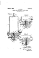
In the said drawing Fig. l is a central vertical section through my improved retarding valve with the parts shown in normal position, that is, the position which they ordinarily occupy when the valve is installed in a sprinkler system; Fig. 2 is a fragmentary View similar to Fig. 1 but showing the parts in a different position, while Fig. 3 is a fragmentary section on line in Fig. 1 looking in the direction of the arrows and with certain parts shown in elevation. Like numerals are used to designate the same parts in the several figures.
As shown, the retarding valve comprises a base 1 having a circular peripheral flange cooperative with a similar flange disposed at the lower end of a dome 2, both flanges being drilled for the passage of bolts 3 by means of which the dome is operat-ively secured on the base. The base is provided with a central downwardly extending boss 4c having a central cavity or valve chamber 5 and and is axiallyv bored and threaded at its lower end for the reception of a bushing 6 formed preferably of brass or other non corrodible metal; the upper end of this bushing when the latter is screwed into place preferably projects for a short distance above the bottom of the valve chamber 5 and forms a flat horizontal seat 7 for a purpose-to be hereinafter described. At the center of this seat is provided a small bore or restricted orifice 8 communicating with y the larger bore 9 in the body of the bushing and which 1s preferably of considerably greater diameter than the orifice. Preferably the lower end of the bushing extends below the boss and is provided with an outwardly directed flange 6 whose perimeter is shaped to form a nut which may be conveniently gripped by a wrench to enable the bushing to bereadily screwed into or out of the boss.
Extended across the bottom of the dome 2 and upper end of the baseis a flexible diaphragm 10 which may be held in place in any suitable way, conveniently by gripping its marginal edge between the flanges with which the base and dome are respectively provided. This diaphragm may be of any suitable material and of ordinary construction and is operative to support at its center a vertically movable valve 11 having an axial bore 12 and an outwardly extending flange 11 at its upper end which adapted to seat on the upper face of the diaphragm, the lat- 'ter of course being centrally perforated for the passage of the valve; Beneath the flaiige the valve may be provided with an external thread adapted for the reception of a clampnut 13 \vhich,'When screwed into position, abuts the under face of the diaphragm and clamps the latter to the valve. The valve ll is of sufiicient length to enable its lower end to seat on the upper end of the bushing 6 when the diaphragm is in a horizontal or substantially horizontal position as shown in Fig. 2, and for constantly yet yieldingly urging the valve and diaphragm upwardly so as to flex the latter and maintain the lower end of the valve normally out of contact with the bushing; a coilspring 14 is loosely disposed about the valve with its lower end resting on the bottom of the valve chamber and its upper end resting against the nut 11, the strength of this springbeing preferably slightly in excess of the exact amount required to flex the diaphragm and hold the valve away from the bushing.
Preferably also the lower end of the spring surrounds the projecting end of the bushing sufiiciently loosely to enable the latter to be screwed in or out without disturbing the spring while the lower end of the valve chamber may desirably be constricted somewhat and arranged to form a suitable seat for the spring.
The dome 2 is provided, preferably near its lower end, with an inlet connection 15 conveniently formed in a suitable boss 16 on the exterior of the dome and to which, when the retarding valve is installed in a sprinkler system, is connected a pipe 17 extending to the alarm check valve and which is operative upon the opening of the latter to convey water from the check valve to the interior of the dome of the retarding valve. For the most satisfactory operation of the device the effective area of this inlet and of the pipe running therefrom to the alarm check valve should ordinarily be greater than the effecthrough the bore in the valve. The dome of the retarding valve is also provided at its upper end with an outlet connection 18 from which a pipe 19 is extended to the alarm devices and through which when an alarm is to be given water is conducted from the interior of the dome as hereinafter described.
The valve chamber 5 is providedwith a drain-connection 20 from which a pipe 21.
may be' extended to the main chain f the system, the drain 20 being preferably so lo cated as to substantially align with the space between the lower end of the valve 11 and the upper end of the bushing when the valve is in elevated or normal'position, andfor conveniently supporting the retarding valvein an upright position when installed in a sprinkler system the base may be provided with an interiorly threaded bore disposed at any suitable point and adapted to receive the threaded end of a supporting rod 22 running to any convenient support.
To enable inspection of a portion of the interior of the valve chamber and to facilitate the cleaning of the lower end of the valve and upper end of the bushing in case of the accumulation of any deposits thereon, I preferably provide the boss 4 with a laterally extending, cylindrical exteriorly threaded projection 25 centrally bored and closed at its outer end by a glass 26 disposed between packing rings 27 and removably maintained in position by a bezel screwed upon the end of the projection. As the bore in the boss is preferablyaligned' with the'upper end of the bushing, the condition of the valve seat and the lower end'of the valve may be readily observed through the glass when desired and, if found to be corroded or tohave accumulated any appreciable deposits, may be readily cleanedby removing the glass and inserting a suitable instrument through the bore, thus'avoiding the necessity of dismantling the retarding valve and breaking the joints in thepipes which are connected to it to enable the cleaning operation to be performed.
The operation ofthe retarding valve when connected in a sprinklersystem as above de scribed is as follows: Under normal conditions, that is, when the alarm check valve of the system is closed, no water can flow through pipe 17 to the in'teriorof the dome so that the latter is dry and valve 11 is held in raised position through the action of spring 14, thus maintaining diaphragm 10 in slightly upwardly flexed condition as shown in Figs. 1 and Upon the opening of the alarm check valve f or any cause water is permitted to flow through pipe 17 into the dome at a pressure substantially equal to that in the risers of the sprinkler system but so long as the diaphragm remains in upwardly flexed condition so as to hold valve 11 away from its seat a free passage is afforded for at least a portion of the incoming water through "bore 12 to the interior of valve chamber 5 and from thence through outlet 20 and pi e 21'to the main drain of the system, so that a large portion of the incoming water is immediately drained from the interior of the dome. However, as the incoming. water is discharged into thevdon e under relatively considerable head while the discharge through valve 11 is under no appreciable head, and also by reason of the fact that the effective area of the inlet and inlet pipe are preferably greater than the effective area of the bore 12 as above noted, the incoming water is not discharged through valve 11 as rapidly as it flows into the dome through the inlet. In consequence, if the inflow is continued for a sufficient time the depth of water in the dome above the diaphragm progressively increases until its weight becomes sufficient to flex the dia phragm downward against the upward thrust of spring 14 until the lower end of the valve engages its seat on the upper end of the bushing, thus preventing any further discharge of water from the dome save for the small quantity which can always pass through orifice 8 irrespective of the position of the valve. Following the closure of the valve 11 in the manner described,- the column of water above the diaphragm builds up with extreme rapidity since practically all of the incoming water is retained in the dome so that within a relatively short time the latter is completely filled and a' flow through pipe 19 to the alarm devices established to set them into operation, this flow thereafter continuing so long as the alarm check valve remains open. Upon the closing of the alarm check valve, however, with consequent cessation of flow to the interior of the dome, the water in the latter is gradually discharged through the orifice 8 until the pressure on the dlaphragm is diminished sufiiciently to allow spring 14 to flex the diaphragm upward to normal position following which the remaining water in the dome is very rapidly discharged through the valve 7 11, thus automatically placing the retarding valve again in condition for operation.
It will be apparent from the foregoing that to establish a flow of water to the alarm devices it is requisite that the alarm check valve remain open at least long enough to permit the building up in the dome of the retarding valve of a column of'water-snfficient to. close valve 11 and fill the dome, and in practice it is customary to so proportion the parts that from fifteen to twenty seconds will be required for this purpose. It
i will also be apparent that any opening of the alarm check valve for a shorter time than this predetermined interval will be ineffective to operate the alarm devices since either an insufficient quantity of water will be admitted to the retarding valve to build up therein a column suificient to close valve 11 or, even though sufficient for that purpose, to thereafter fill the dome and pass to the alarm devices. Consequently, any momentary opening of the alarm check valve on account of variations in the pressure within the system or from any cause other than the opening of a sprinkler head, a serious leak will not thereafter collect in the dome in sufiicient quantity to completely fill the dome and flow to the alarnrdevices.
While I have herein described and illustrated one form of my invention with considerableparticularity, I do not thereby desire or intend to limit myself precisely thereto, as various changes and modifications may be made in the details of the design, construction and arrangement of the parts with out departing from the spirit and scope of the invention as defined in the appended claims.
Having thus described my invention, I claim and desire to protect by Letters Patent of the United States: I
l. A retarding valve for automatic sprinkler systems comprising a dome having an inlet adjacent its lower end and an outlet adjacent its upper end, a flexible diaphragm extended across the lower end of the dome, a valve chamber beneath the diaphragm, a valve movable with the diaphragm and having a passage extending from the interior of the dome to the interior of the valve chamber, a seat adapted to close said passage when engaged by the valve, a restricted orifice leading from the valve chamber adapted to drain water from the dome irrespective of the position. of the valve, a discharge port leading from the valve chamber, and yielding means tending to flex the diaphragm so as to normally hold the valveout of contact with said seat.
2. A retarding valve for automatic sprinkler systems comprising a dome having an inlet near its lower end and an outlet near its upper end, a base connected to the dome and providing a valve chamber, a diaphragm separating the interior of the dome from the chamber, a valve carried by the diaphragm extending into the valve chamber and having a passage adapted to alford communication between the interior of the dome and the chamber, a seat for the valve operative to close said passage when the valve is engaged therewith, and means for yieldingly urging the diaphragm in a direction to nor mally hold the valve out of engagement with the seat. Y
8. A retarding valve for automatic sprinkler systems comprising a dome having an inlet near its lower end and an outlet near its upper end, a base connected to the dome and providing a valve chamber having a discharge port leading therefrom, a diaphragm separating the interior of the dome from the valve chamber, a valve carried by the diaphragm, extending into the valve chamber and having a passage adapted to afford communication between the interior of the dome and the valve chamber, a seat in the valve chamber for the lower end of the valve operative to close said passage when the valve is seated thereon, means for yieldingly urging the diaphragm in a direction to normally hold the valve out of engagement with the seat and a restricted ori fice in the seat aligned with the passage in the valve.
- 4. A. retarding valve for automatic sprinkler systems comprising a dome having an inlet near its lower end and an outlet near its upper end, a base disposed beneath and connected to the dome and providing a valve chamber, a flexible diaphragm separating the valve chamber from the interior of the dome, a valve carried by and extending through the diaphragm and having a passage from one of its ends to the other atlording communication from the interior of the dome to the interior of the valve chamber, a discharge port leading from the valve chamber, a valve seat in the valve chamber aligned with the valve and operative to close the passage therethrough when the valve is seated thereon, a restricted orifice extending through the seat and aligned with the passage in the valve, and means for yieldingly urging the diaphragm in a direction to normally hold the valve from engagement with the seat to permit an unobstructed flow of fluid from the dome through the valve and into the valve chamber.
5. A retarding valve for automatic sprin kler systems comprising a dome having an inlet near its lower end adapted to admit fluid to its interior and an outlet near its upper end, a valve chamber arranged below the dome, a diaphragm separating the valve chamber and the interior of the dome, a tubular valve extending vertically through and carried by the diaphragm, a valve seat in the valve chamber adapted to close the passage through the valve when its lower end is seated thereon, yielding means for continually urging the diaphragm in a direction to normally maintain the lower end of the valve out of engagement with the seat, a port leading from the valve chamber and adapted to discharge fluid admitted thereto through the valve and a restricted orifice disposed in the seat in alignment with the passage in the valve adapted to permit the escape of a limited quantity of fluid from the dome irrespective of the position of said valve.
6. A retarding valve for automatic sprinlzler systems comprising a dome having an inlet near its lower end and an outlet near its upper end, a diaphragm extended across the lower end of the dome, a base beneath the diaphragm, secured to the dome and providing a valve chamber, a tubularvalve extending through the diaphragm and movable therewith, a seat for the lower end of the valve arranged in the valve chan'iber and operative to prevent the passage of fluid through the, valve when. the valve is in engagement with the sea t, yielding means tending to hold the valve out of engagement with the seat, and a restricted orifice in the seat aligned with the passage in the valve and operative to drain fluid from the interior of the dome irrespective of the position of said tubular valve.
7. A retarding valve for automatic sprinkler systems comprising a dome having an inlet and an outlet, a valve chamher disposed adjacent the dome and having a drainleading therefrom, a flexible diaphragm separating the chamber from the interior of the dome, a valve seat in the valve chamber, a valve carried by the diaphragm and cooperative with said seat to prevent the passage of fluid from the interior of the dome to the chamber when in one position and to permit said passage when in another position, yielding means operative to normally maintain the valve in said last mentioned position, and a restricted orifice arranged to drain fluid from the interior of the dome irrespective of the position of the valve.
In witness whereof, I have hereunto set my hand this 27th day of April, 1926.
LEROY M. LEWVIS.
Publications (1)
| Publication Number | Publication Date |
|---|---|
| US1663136A true US1663136A (en) | 1928-03-20 |
Family
ID=3414722
Family Applications (1)
| Application Number | Title | Priority Date | Filing Date |
|---|---|---|---|
| US1663136D Expired - Lifetime US1663136A (en) | A corpora |
Country Status (1)
| Country | Link |
|---|---|
| US (1) | US1663136A (en) |
Cited By (1)
| Publication number | Priority date | Publication date | Assignee | Title |
|---|---|---|---|---|
| US3071150A (en) * | 1961-02-17 | 1963-01-01 | Aqua Matic Inc | Liquid level control valve |
-
0
- US US1663136D patent/US1663136A/en not_active Expired - Lifetime
Cited By (1)
| Publication number | Priority date | Publication date | Assignee | Title |
|---|---|---|---|---|
| US3071150A (en) * | 1961-02-17 | 1963-01-01 | Aqua Matic Inc | Liquid level control valve |
Similar Documents
| Publication | Publication Date | Title |
|---|---|---|
| US3584689A (en) | Dry-type sprinkler | |
| US2101991A (en) | Flush tank valve apparatus | |
| US1663136A (en) | A corpora | |
| US2019421A (en) | Attachment for refrigerating systems | |
| US1982062A (en) | Float valve | |
| US2272304A (en) | Antisiphon valve | |
| US1819827A (en) | Sanitary vent for pressure milk tanks | |
| US1032352A (en) | Drain-valve. | |
| US2135522A (en) | Liquid level indicator | |
| US2496465A (en) | Automatic primer | |
| US1362223A (en) | Fire-extinguisher | |
| US1729493A (en) | Safety device for cleaning plants or the like | |
| US1536078A (en) | Flushing valve for water-closets | |
| US1730127A (en) | Oil-display pump | |
| US1855682A (en) | Alarm device for fluid pressure regulators | |
| US2300825A (en) | Storage tank vent valve | |
| US1539020A (en) | Gasoline strainer | |
| US1885348A (en) | Air valve structure for pipe lines | |
| US1009044A (en) | Vent-valve for water or other liquid carrying conduits. | |
| US2731979A (en) | Inlet valve for toilet flush tank | |
| US1623510A (en) | Fire extinguisher | |
| US2052332A (en) | Differential pressure valve | |
| US2412095A (en) | Pressure switch | |
| US2213527A (en) | Sprinkler head | |
| US2236350A (en) | Oil and dirt accumulator for low pressure heating systems |