US1663014A - Well-underreaming tool - Google Patents
Well-underreaming tool Download PDFInfo
- Publication number
- US1663014A US1663014A US586137A US58613722A US1663014A US 1663014 A US1663014 A US 1663014A US 586137 A US586137 A US 586137A US 58613722 A US58613722 A US 58613722A US 1663014 A US1663014 A US 1663014A
- Authority
- US
- United States
- Prior art keywords
- tool
- piston
- bore
- well
- drilling
- Prior art date
- Legal status (The legal status is an assumption and is not a legal conclusion. Google has not performed a legal analysis and makes no representation as to the accuracy of the status listed.)
- Expired - Lifetime
Links
- 238000005553 drilling Methods 0.000 description 15
- 239000007788 liquid Substances 0.000 description 13
- 239000012530 fluid Substances 0.000 description 7
- 230000001050 lubricating effect Effects 0.000 description 4
- 230000015572 biosynthetic process Effects 0.000 description 3
- 238000005755 formation reaction Methods 0.000 description 3
- 238000010348 incorporation Methods 0.000 description 2
- 239000003129 oil well Substances 0.000 description 2
- XLYOFNOQVPJJNP-UHFFFAOYSA-N water Substances O XLYOFNOQVPJJNP-UHFFFAOYSA-N 0.000 description 2
- 241000507564 Aplanes Species 0.000 description 1
- 238000006073 displacement reaction Methods 0.000 description 1
- 238000012423 maintenance Methods 0.000 description 1
- 238000005086 pumping Methods 0.000 description 1
- 235000002020 sage Nutrition 0.000 description 1
Images
Classifications
-
- E—FIXED CONSTRUCTIONS
- E21—EARTH DRILLING; MINING
- E21B—EARTH DRILLING, e.g. DEEP DRILLING; OBTAINING OIL, GAS, WATER, SOLUBLE OR MELTABLE MATERIALS OR A SLURRY OF MINERALS FROM WELLS
- E21B10/00—Drill bits
- E21B10/26—Drill bits with leading portion, i.e. drill bits with a pilot cutter; Drill bits for enlarging the borehole, e.g. reamers
- E21B10/32—Drill bits with leading portion, i.e. drill bits with a pilot cutter; Drill bits for enlarging the borehole, e.g. reamers with expansible cutting tools
- E21B10/322—Drill bits with leading portion, i.e. drill bits with a pilot cutter; Drill bits for enlarging the borehole, e.g. reamers with expansible cutting tools cutter shifted by fluid pressure
Description
March 20, 1928. 1,663,014
* M. C. LOWMAN ET AL WELL UNDERREAMING TooL 5, M5 Z im wrf., wa ONN 5M E@ C5 MAW m r 4 pm@ mem Mm@ March 20, 1928.
M. C. LOWMAN ET AL WELL UNDERREAMING TOOL Filed Sept. 5, 1922 2 Sheets-Sheet 2 www@ a N65 E [man m Inma T may 00 M 5 Z 0 40 5 4 4 5 2 w //w//////6 ,////e w ,WWMSMMMM V I H 5 f 4 x w M ,d
' i MALDN C. LOAN AND GEORGE E. FENTRESS, OF LOS ANGELES,
OF FULLEBTON, CALEORNIA.
i WELL-UNDEBBE :me Toor..
Application led September 5, 1922. Serial No. 588,137.
l This invention relates to well drilling equipment and relates particularly to hydraulic rotary equipment such as is 'used in oil Well drilling.
In the drilling of oil wells, considera-ble diiiculty is encountered .in maintaining the full diameterof bore owing to the wearing off of the corners and sides of the well drilling bits so that the bit does not eut to its full original diameter. It is necessary that the full diameter of the bore be maintained in order that the casing lmay enterl freely into the hole, as it is installed. It is-quite oftennecessary to employ underreamers for the purpose of reamin the holes to large enough diameters to permit the casing to advance.
4Unde'rreamers generally employed are of y the expanding type and are lowered through the casing to the point at which it is` desired to operate and the blades of the underreamer expanded. In order toemploy a separate underreamer, the drilling tool must 'first be lifted from the Welland the underreamer screwed upon the lower end of the drill pipe. This removing of the drill pipe from the well consumes a ver considerable portion of the time inwhic the, drilling equipment is in operation and where hard formations are being operated in, such as cause the drilling tool to wear away quickl the depth of the hole advances very slow y vowing to the slow cuttin speed of the tool and the necessity. of wit drawing the line of drill pipe from the well inl order to place an underreamer thereabout.
It is an object of the invention to provide a new underreamer suitable to be incorporated in one body with a drilling bit; but adapted to separate use, thus making 1t possible to employ either the drillm bit or the underreamer-'and eliminatingt e .neces- .sity of pulling the string of'drill pipe as hereinbefore mentioned,fwhen the use of an underreamer-is required. y
Itis also' an object of the invention to p rovide a tool of this character having reaming elements which are ordinarily maintained 1n retracted position, but which are adapted to be extended, for thepurpose of operating upon the walls of the drill hole, by pumping an excess pressure upon the; u ricating liquid.
It is a further object of the invention to provide a device of this character having removable underreaming blades.
vIt is a further object of' the invention to provide a device of this character in which the entire pressure of the lubricating liquid maybe exerted against the bottom of an operating piston thereof as it is raised, to expand the underreaming blades.
The'special advantages of our invention. and further objects `thereof will be made evidentI hereinafter. Referringto the drawings which are for illustrative purposes only, f
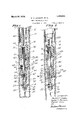
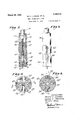
Fig. 1 is a sectional view taken substan-` tially upon aplane represented by the line 11 of Fig. v4, showing a drilling tool with :which is associated an underreaming tool embodying the invention, the underreamin elements of the tool being shown in retracte position while a tool is employed for the purpose of increasing the de th of the hole.
Fig. 2 isla sectional View s derreamer elements ofthe tool employed for the diameter, of the ho be advanced. therein.
Fig. 3 is a section taken on a plane represented by the line 3-3 of Fig. 1.
Fig. 4 is a section taken on a plane represented hy the line 4 4 of Fi 1.y l
Fig. 5 is a vertical section tien u on la plane represented by the line 5 5 of FPig. 3.
Fig. 6 is an external view of the device,
owing the unurpose of increasing the atm naar is:
e so that the casing'may' 7 5, .A expanded and one ofthe blade channels being directed toward the beholder, in this view. v l
As shown in the drawing, they invention employs a body 11 having a tool joint 12atA the upper end ,thereof b which it may be connected into a .line o drill pipe. This body 11 is com rised of an upper member 14 provided wit a bore 15 which is enlarged at its lower end, as indicated at 16, and a is..
lower Amember '18 which screws into the upper member 14 at 19. In the lower end of-the'member 18 a removable cutting blade I 20 is held in a crosswise slot 21 in aterminal head and is securedtherein against lateral displacement by screws 22. It will be erceived that the upperv portion 24 of the b ade 2O is the largest point inthe blade and that the blade gradually tapersas it progresses same formation, thus downwardly The slot 21 'adheres to this roviding a perfect interlock between the b ade and the slot, so that the blade cannot4 be removed vertically therefrom, but can only be removed by taking outV the screws 22 and `slidingthe blade laterally from the slot.
Laterally upon each side ofthe lower member '18 but'above'the mentioned terminal head, shown as 'provided with slot 21, and
.j diametrally dis osed one from the other,
a pair of channe s having inwardly downwardly sloping bottoms 31 are formed, intol which underreamer elements 32 each 'com'- prised of a block 33 which dovetails into a channel 30, as indicated at 34 in Figs.,3 and '4, and has vertical channels 35 into which removable blades 36 are also dovetailed. 'The underreamerelements ordinarily .rest at the bottoms of the channels 30 and in this pof sition hold the blades 36--retracted-as shownin Fig. 1. In order to bring the blades into operatin-gdposition, the underreamer elements Yare move y ing channels-30 to their positionsof full upwardly in the 'outwardly slopprojection, as indicated in lFig. 2. The manpiston, 40. Downwardly from the bottom of the bore 38 a smaller bore 42 is continued. U on each side ofthe large bore 38 vertical i ho es 43 are drilled down toa depth e ual to that of the bore 38- and a diametral ole 45I is drilledl across the member 18 ata' point which will 4connect the bottoms of the drill holes 43 with the bottom of the bore 38, the
ends of the Vholes 45 being afterward plugged,
` as shown at 46. 'A smaller plunger 450, having a j. wardly from the bottom ofthe piston 40 through a collar 53' which is threaded into 'the upper end of the small bore 42 fand "is provided with a bore 54 of substantially the samediam'eter as the (plunger 50..
. It 'willbe' perceive that a space is pr o' 'vided between the outer face of the plunger i and thewalls of the bore When the tool is-i'nemployment for drilling purposes vthe water, introduced through the bore 15 55` of the upper member 14, travels downwardly past acap l55 which maintains a'sprin'g. 56 Iin com ression against the top e 40', an entering the drill ho s '43 is delivered through' the cross channel 45, under the of the piston 40, through the norbottom en mally open space ofthe bore 54 in the collar 53 surroundin the shank 51, past the plunger 50, and na y through a vertical hole 58 to the drill bit 20.
It will be perceived that the pressure of.
reduced shank 51,'is lextended down-y v of the piston vof t e, spring 56.
the lubricating water is at' all timesexerted upon the bottom of the piston 40. This feature is employed to cause the expansion or projection of the reamer elements by increasing the pressure on the lubricating liquid being delivered, so that the piston will be v forced upwardly against the `action of the sprin 56. The movement of the piston is v transl erred through a horizontal bar 60 whichv extends through the upper end of thepiston 40, through a vertical slot 62, and engages holes 63 ovided in the 'upper end s of the blade holding blocks 33 of the reamerl elements.
It will be noticed that the passage provided around theshank 51 and around the plunger 50y is considerably smallervinarea than the passage provided Aby the vertical holes 43 so that when an additional pressure is exerted upon the column of lubricating liquid being delivered, a pressure will be built up above the collar v53 which will be exerted against the piston 40 and-causethe-lifting of thereainer elementsA 32, whereupon they travel outwardly in the channels 30 and may assume the positions at the tops of the channels in which they are shown in Fig: 2. The plunger 50 is carried upwardly with the piston and enters into the bore ofthe collar 53 as shown in Fig. 2, thus substantially shuttin off the flow of liquid and making it possi le to exert the entire pressure ,of the liquid upon the underside of thepston 40 so that its elevation-'into an upper position will be assured.` The plunger 50 may be of such a length' that vwhen the piston '40 is entirely raised, as shown in Fig. 2, the lower end 57 of the plunger is above the opening 54 through the collar-'53 and permits the pas# sage of theliquid therethrough into the bore .42 from whence ,it circulates upwardly between the reamer blades and keeps them free from collecting mud.
vides an automatic discharge valve which adjusts the closure'of the outlet to suit the pressure upon the mud within the bore 39' so that the maintenance of the reamer blades in raised position is'at all times assured. In
other'words, if the pressure in the line of drill `pipe should drop so that the piston 40 and the blades. 36 recede, the Vplunger 50 would immediately enter the collar`53`\ and It will be perceived that the plunger pro'-V shutoff all discharge of'liquid therethrough,
thus-retaining the entire pressure of the l1q' uidwithin the bore-39, which would prevent the lunger fromreceding under the action A particulanfatureof our invention resides in the fact that the reamer blades expand with an upward travel of the blocks 32 in which. they are held thus preventing the possibility of the bla es aminin by expanding as the tool is raiserl in the hole; and that the upward action of the walls of the hole against theblades 36 when reaming assists in holding the blades in raised position.-
Although this device is adapted to the use of the cutter and the reamer elements thereof separately, it is also possible and in many instances-desirable' to bring both the cutting and the reamer elements into action at the same time so that the reaming action Will be accomplished as the drilling operation proceeds. This combination'drilling and reaming, of course, would require considerably more power to drive the ltool than if each are employed separately; therefore, our invention is adapted to suit the capacity of the drilling equipment.
rIhe device shown herein makes it possible `4to place a tool upon the lower end of a string of drill pipe, and upon lowering it to the bottom of the Well, to drill an additinaldepth of hole, this depth depending upon the abrasive nature of the formation being operated upon; to then raise the tool to a point4 directly beneath the bottom of the casing 65, whereupon the underre'amer elements may be expanded so as .to enlarge the hole, as indicated at 68 in Fig. 2, to permit 'the casing to enter further into the hole. A particular valuable feature of the invention is that after each drilling operation, the cutting blade 20 and the lreaming bladesv 36 may be replaced without great delay, and also that a drilling and a reaming operation may be performed at each lowering of the string of drill pipe. y
We claim as our invention;
1. In a well tool, the combination of: a body, having a fluid passage, adapted for securing to a drill pipe and comprising a member having longitudinal reamer channels and a head therebelow: projectile cutting means carried by said body; means actuable by fluid pressure for projecting said cutting means; and means whereby obstruction of said fluid passage is effected when said projecting means is actuated.
2. In a well tool, the 'combination of: a
varranged for body adapted for securing to a drill pipe, said body having a fluid passage therein, and having channels therein which diverge as they progress upwardly; blocks slidable in said channels; reamer elements held by said blocks; a piston operable by fluid delivered under pressure through said drill pipe; said piston being arranged to move said blocks; and resilient means for resisting the advance of said piston; and means for obstructing said iuid passage when said piston is actuated.
3. In a well tool, the combination of: a body'arranged for incorporation in a string of drill pipe and comprising a member having l`ongitudinal reamer channels and a head therebelow, said body having a passage constricted near the end thereof, for circulation of liquid; projectile members carried by said body; and fluid operated means associated with said passage at a point above the constricted portion thereof arran ed for projecting Asaid projectile members W en the pressure of said liquid is raised above a predesighated value; and valve means for reducing the flow of said liquid when said fluid operated means is actuated.
4. In a Well tool, the combination of: a body arranged for incorporation in a string of drill pipe and comprising a member having longitudinal reamer channels and a head therebelow, said body having a passage for `circulation of liquid; projectile members carried by said body; and piston means rojecting said projectile members when t e pressure of said liquid is raised above a predesignated value; and a. valve member linked with said piston means for reducing the flow of said liquid when said piston .is actuated.
In testimony whereof, we have hereunto set our hands at Los Angeles, California,
this 24th day of August, 1922.
MALDEN C. LOWMAN. GEORGE E. FENTRESS. ROBERT BANE.
Priority Applications (1)
| Application Number | Priority Date | Filing Date | Title |
|---|---|---|---|
| US586137A US1663014A (en) | 1922-09-05 | 1922-09-05 | Well-underreaming tool |
Applications Claiming Priority (1)
| Application Number | Priority Date | Filing Date | Title |
|---|---|---|---|
| US586137A US1663014A (en) | 1922-09-05 | 1922-09-05 | Well-underreaming tool |
Publications (1)
| Publication Number | Publication Date |
|---|---|
| US1663014A true US1663014A (en) | 1928-03-20 |
Family
ID=24344465
Family Applications (1)
| Application Number | Title | Priority Date | Filing Date |
|---|---|---|---|
| US586137A Expired - Lifetime US1663014A (en) | 1922-09-05 | 1922-09-05 | Well-underreaming tool |
Country Status (1)
| Country | Link |
|---|---|
| US (1) | US1663014A (en) |
Cited By (1)
| Publication number | Priority date | Publication date | Assignee | Title |
|---|---|---|---|---|
| US2588068A (en) * | 1948-01-09 | 1952-03-04 | Cons Edison Co New York Inc | Drilling apparatus |
-
1922
- 1922-09-05 US US586137A patent/US1663014A/en not_active Expired - Lifetime
Cited By (1)
| Publication number | Priority date | Publication date | Assignee | Title |
|---|---|---|---|---|
| US2588068A (en) * | 1948-01-09 | 1952-03-04 | Cons Edison Co New York Inc | Drilling apparatus |
Similar Documents
| Publication | Publication Date | Title |
|---|---|---|
| US2690897A (en) | Combination mill and under-reamer for oil wells | |
| US3050122A (en) | Formation notching apparatus | |
| US2136518A (en) | Pipe cutter | |
| US3656564A (en) | Apparatus for rotary drilling of wells using casing as the drill pipe | |
| US2049450A (en) | Expansible cutter tool | |
| US3989114A (en) | Circulation sub for in-hole hydraulic motors | |
| US3289760A (en) | Method and apparatus for cementing and conditioning bore holes | |
| US2799479A (en) | Subsurface rotary expansible drilling tools | |
| US3339647A (en) | Hydraulically expansible drill bits | |
| US3211244A (en) | Method and apparatus for performing multiple operations in well bores | |
| US2716018A (en) | Apparatus for bore hole drilling | |
| US2307658A (en) | Well washing tool | |
| US2170452A (en) | Expansible reamer | |
| US3661218A (en) | Drilling unit for rotary drilling of wells | |
| US1750953A (en) | Rotary reamer | |
| US1858926A (en) | Oil tool device | |
| US1589508A (en) | Rotary reamer | |
| US2252912A (en) | Well tool | |
| US1663014A (en) | Well-underreaming tool | |
| US2120240A (en) | Drilling apparatus | |
| US1857616A (en) | Hydraulic underreamer | |
| CN105888558B (en) | Downhole reamer | |
| US2179033A (en) | Method and apparatus for performing fishing operations | |
| US2941785A (en) | Expansible rotary drill bit | |
| US2221392A (en) | Core catcher |