US1663013A - Battery terminal - Google Patents
Battery terminal Download PDFInfo
- Publication number
- US1663013A US1663013A US714254A US71425424A US1663013A US 1663013 A US1663013 A US 1663013A US 714254 A US714254 A US 714254A US 71425424 A US71425424 A US 71425424A US 1663013 A US1663013 A US 1663013A
- Authority
- US
- United States
- Prior art keywords
- post
- battery
- arm
- battery terminal
- connector
- Prior art date
- Legal status (The legal status is an assumption and is not a legal conclusion. Google has not performed a legal analysis and makes no representation as to the accuracy of the status listed.)
- Expired - Lifetime
Links
Images
Classifications
-
- H—ELECTRICITY
- H01—ELECTRIC ELEMENTS
- H01R—ELECTRICALLY-CONDUCTIVE CONNECTIONS; STRUCTURAL ASSOCIATIONS OF A PLURALITY OF MUTUALLY-INSULATED ELECTRICAL CONNECTING ELEMENTS; COUPLING DEVICES; CURRENT COLLECTORS
- H01R11/00—Individual connecting elements providing two or more spaced connecting locations for conductive members which are, or may be, thereby interconnected, e.g. end pieces for wires or cables supported by the wire or cable and having means for facilitating electrical connection to some other wire, terminal, or conductive member, blocks of binding posts
- H01R11/11—End pieces or tapping pieces for wires, supported by the wire and for facilitating electrical connection to some other wire, terminal or conductive member
- H01R11/28—End pieces consisting of a ferrule or sleeve
- H01R11/281—End pieces consisting of a ferrule or sleeve for connections to batteries
Definitions
- An object of the invention is to provide a device of this character constructed in such a manner that it can be easily and quickly applied to the post of a battery and when in place thereon will reduce .the corrosion of parts due to vapors arising from the battery to a minimum.
- a further object of the invention is to provide a device of this character in which the post to which the lead in connection is secured is remote from the vent opening of the battery.v
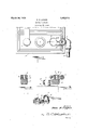
- Figure 1 is a top plan View of a portion of a storage battery having the deviceof my invention secured thereon,
- FIG. 1 is a vertical sectional view taken I on the line 22'of Figure 1
- Figure 3 is a vertical sectional view taken on the line 33 of Figure 1, and
- Figure 4 is a perspective View of the device.
- 1 designates a conventional form of bat: ery provided with the usual negative and positive posts 2 and 3, respectively.
- an arm 4 Adapted to be fixed to the post 3 is an arm 4, said a'rm having an opening 5 in its inner end for receiving the post 3.
- This arm when in place is horizontally disposed and spaced from the top of the battery 1 and has its outer end provided ,with an integral vertically extending post6 to which is clamped the usual connector 7 to which the lead wire 8 is'c'onnected;
- connection of the post 6:and the connector 7 must be released, and remade many times in the life of a battery and means must be provided for assuring a good clean contact therebetween.
- the cup 10 is provided inthe post 6 and has small openings 11 communicating therewith and passing to theouter surface of the post 6.
- the cup 10 is filled, preferably with Vaseline or cup grease and when the connector is secured tightly in place suflicient of the vaseline is forced through aperturesll to collect I in a film between the post and connector to eliminate corrosion and thereby insure a good contact.
- the pressure of Arm on the top of the-filled cup serves to force the Vaseline through the aperture 11-.
- a terminal attachment for storage bat. teries comprising an arm having a tapered bore adapted to be fixed 'upona correspondingly tapered terminal of a storage battery, a tapered most arising from one end of said arm and disposed in offsetv relation with respect to said terminal, the diameter'and taper of said post being the same as that of said bore, said post being adapted to deta'chably receive a leadiconnector and to maintain said connecter spaced from said battery terminal.
Description
March 20, 1928.
1,663,013 T. LOGAN BATTERY TERMINAL Filed May 19, 1924 IIIIIIIII -y Patented Mar. 20, 1928.
TOM Ill LOGAN, 0F COLUMBUS, OHIO.
BATTERY Application filed ma 19 The present invention is directed to improvementsin devices for protecting battery connections.
An object of the invention is to provide a device of this character constructed in such a manner that it can be easily and quickly applied to the post of a battery and when in place thereon will reduce .the corrosion of parts due to vapors arising from the battery to a minimum.
A further object of the invention is to provide a device of this character in which the post to which the lead in connection is secured is remote from the vent opening of the battery.v
With these and other objects in view, as will appear as the description proceeds, the
' invention consists in the novel features of a construction, combinations of parts hereinafter to be fully described and claimed.
In the accompanying drawing: Figure 1 is a top plan View of a portion of a storage battery having the deviceof my invention secured thereon,
Figure 2 is a vertical sectional view taken I on the line 22'of Figure 1,
Figure 3 is a vertical sectional view taken on the line 33 of Figure 1, and
Figure 4; is a perspective View of the device. M r
Referring to the drawing in detail, in which like reference numerals refer to like parts throughout the several views. i
1 designates a conventional form of bat: ery provided with the usual negative and positive posts 2 and 3, respectively.
Adapted to be fixed to the post 3 is an arm 4, said a'rm having an opening 5 in its inner end for receiving the post 3. This arm when in place is horizontally disposed and spaced from the top of the battery 1 and has its outer end provided ,with an integral vertically extending post6 to which is clamped the usual connector 7 to which the lead wire 8 is'c'onnected;
It will be. observed that when the arm 4- is in place "moisttire and vapors which may collect upon' post 3 and causes corrosion, will .be largely prevented from reaching the post 6, consequently eliminating corrosion at this point. It will be 'observed that should moisture collect upon the post 3 the likeli- TERMINAL.
, 1924. .Serial No. 714,2.
7 hood of the same passing to the post 6 is small owing to the presence of the shoulder 9 formedby the lower surface. of the inner end of said arm. Any moisture which does collect upon the lower surface of the arm will by gravity drop therefrom and consequently will not reach the post 6 and connector 7, thereby eliminating possibility of corrosion. I
To secure the arm to the post 3 it is only necessary to apply the flame from a blow torch to cause parts of the post 3 and arm 4 to fuse. Thus the best possible permanent contact of the parts is obtained in such a way as to reduce corrosion to a minimum.
The connection of the post 6:and the connector 7 must be released, and remade many times in the life of a battery and means must be provided for assuring a good clean contact therebetween.
- For this purpose the cup 10 is provided inthe post 6 and has small openings 11 communicating therewith and passing to theouter surface of the post 6.
Inmaking the connection itis first assured that the interior of the connector and the exterior of post 6 are thoroughly clean, the cup 10 is filled, preferably with Vaseline or cup grease and when the connector is secured tightly in place suflicient of the vaseline is forced through aperturesll to collect I in a film between the post and connector to eliminate corrosion and thereby insure a good contact. The pressure of afinger on the top of the-filled cup serves to force the Vaseline through the aperture 11-.
What is claimed is: y
A terminal attachment for storage bat. teries comprising an arm having a tapered bore adapted to be fixed 'upona correspondingly tapered terminal of a storage battery, a tapered most arising from one end of said arm and disposed in offsetv relation with respect to said terminal, the diameter'and taper of said post being the same as that of said bore, said post being adapted to deta'chably receive a leadiconnector and to maintain said connecter spaced from said battery terminal.
In testimony whereof I aflix my signature.
TOM P. IQOGAN.
Priority Applications (1)
| Application Number | Priority Date | Filing Date | Title |
|---|---|---|---|
| US714254A US1663013A (en) | 1924-05-19 | 1924-05-19 | Battery terminal |
Applications Claiming Priority (1)
| Application Number | Priority Date | Filing Date | Title |
|---|---|---|---|
| US714254A US1663013A (en) | 1924-05-19 | 1924-05-19 | Battery terminal |
Publications (1)
| Publication Number | Publication Date |
|---|---|
| US1663013A true US1663013A (en) | 1928-03-20 |
Family
ID=24869316
Family Applications (1)
| Application Number | Title | Priority Date | Filing Date |
|---|---|---|---|
| US714254A Expired - Lifetime US1663013A (en) | 1924-05-19 | 1924-05-19 | Battery terminal |
Country Status (1)
| Country | Link |
|---|---|
| US (1) | US1663013A (en) |
Cited By (3)
| Publication number | Priority date | Publication date | Assignee | Title |
|---|---|---|---|---|
| US2801399A (en) * | 1955-04-01 | 1957-07-30 | Loyal T Dunn | Circuit breaker |
| US3042891A (en) * | 1959-10-29 | 1962-07-03 | Richard A Navarro | Battery terminals |
| DE10335733A1 (en) * | 2003-08-05 | 2005-03-10 | Daimler Chrysler Ag | Polklemme |
-
1924
- 1924-05-19 US US714254A patent/US1663013A/en not_active Expired - Lifetime
Cited By (5)
| Publication number | Priority date | Publication date | Assignee | Title |
|---|---|---|---|---|
| US2801399A (en) * | 1955-04-01 | 1957-07-30 | Loyal T Dunn | Circuit breaker |
| US3042891A (en) * | 1959-10-29 | 1962-07-03 | Richard A Navarro | Battery terminals |
| DE10335733A1 (en) * | 2003-08-05 | 2005-03-10 | Daimler Chrysler Ag | Polklemme |
| US7001226B2 (en) | 2003-08-05 | 2006-02-21 | Daimlerchrysler Ag | Connecting cable |
| DE10335733B4 (en) * | 2003-08-05 | 2013-09-26 | Daimler Ag | Polklemme |
Similar Documents
| Publication | Publication Date | Title |
|---|---|---|
| GB1529398A (en) | Connecting devices | |
| US1663013A (en) | Battery terminal | |
| US1507936A (en) | Storage-battery terminal | |
| US1469119A (en) | Electrolyte gas and splash escape | |
| US1303464A (en) | Distant-control-switch socket fob electbic lights | |
| US1951591A (en) | Protection terminal for batteries | |
| US2237097A (en) | Terminal clamp for battery posts | |
| US2079495A (en) | Dry cell and seal therefor | |
| US3457542A (en) | Battery terminal connector | |
| US1957131A (en) | Corrosionproof battery terminal | |
| US2450467A (en) | Polarized house wiring receptacle and plug | |
| US3125394A (en) | Explosion proof plug and receptacle | |
| US2041824A (en) | Storage battery terminal | |
| US1542676A (en) | Battery case | |
| US1852366A (en) | Terminal for storage batteries | |
| US1452806A (en) | Storage-battery vent | |
| US1421017A (en) | Battery connector | |
| US541350A (en) | Portable galvanic-battery cell | |
| US2264188A (en) | Sealing battery terminal | |
| US1661854A (en) | Storage-battery device | |
| JPH03503696A (en) | Corrosion resistant battery terminals | |
| US975875A (en) | Electric plug and socket. | |
| JPS609680B2 (en) | rechargeable electronics | |
| US2074260A (en) | Safety gauge for batteries | |
| US2289927A (en) | Battery terminal clamp |