US1663010A - Variable element - Google Patents
Variable element Download PDFInfo
- Publication number
- US1663010A US1663010A US689434A US68943424A US1663010A US 1663010 A US1663010 A US 1663010A US 689434 A US689434 A US 689434A US 68943424 A US68943424 A US 68943424A US 1663010 A US1663010 A US 1663010A
- Authority
- US
- United States
- Prior art keywords
- rotor element
- semi
- stator
- rotor
- pair
- Prior art date
- Legal status (The legal status is an assumption and is not a legal conclusion. Google has not performed a legal analysis and makes no representation as to the accuracy of the status listed.)
- Expired - Lifetime
Links
Images
Classifications
-
- H—ELECTRICITY
- H01—ELECTRIC ELEMENTS
- H01F—MAGNETS; INDUCTANCES; TRANSFORMERS; SELECTION OF MATERIALS FOR THEIR MAGNETIC PROPERTIES
- H01F21/00—Variable inductances or transformers of the signal type
- H01F21/005—Inductances without magnetic core
Description
March 20, 1928.
W. KAISLING VARIABLE ELEMENT Filed Jan. 30, 1924 Patented Mar. 20, 1928.
UNITED STATES PATENT OFFICE.
WILLIAM KAISLING,. OF- CHICAGO, ILLINOIS, ASSIGNOR TO KELLOGG SWITCHBOABD AN D SUPPLY COMPANY, OF CHICAGO, ILLINOIS, A. CORPORATION OE. ILLINOIS.
VARIABLE ELEMENT;
Application filed January 30, 1924. Serial No. 689,434.
My invention relatesto variable elements, transformers or inductances and has to do more particularly with a pairof coils, one stationary and the other rotatable, Inside of the stationary coil' and is'adapted' particularly for use in radio receiving systems and an object of my invention is'to produce a device compact, and simple in construction, li ht yet durable, efiicient in operation and relatively low in cost of manufacture.
The variable-inductance or element of my invention is particularly adapted for-use in radio receiving systems which are equipped with. stages of radio frequency and adapted itself for use as a radio frequency trans former in which the rotor winding of the rotor element is used as the primary of a transformer and the stator or stationary winding as the secondary of the transformer. The design of my variable element or inductance permits the same to be easily adjusted through a.wide range of values and also accommodates a large range of wave lengths. Due to the construction of my variable element, a device is provided which is of relatively low and constant electrical resistance and of low or small. distributed capacity.
A feature of my invention is a provision of an improved rotor and stator assembly in which the, stator element is in the'form' of a pair of semi-circular members which are provided with concave portions. which form a spherical opening when the membersare clamped together to form a cylindricalmemher. The rotor element is adapted to rotate in said spherical opening and is rotatably. supported by a pair of. shafts which maintain the said rotor element. in concentric. relation with the spherical opening.
Another feature of. my invention is the provision of anovelterminal arrangement to which the outside terminal. ends of the. re.- spective primary rotor winding and secondary stator winding are secured, andmeans provided in associationv with the said terminals for, permittingv the. respective. terminals to be connected to the external circuits.
Still another feature of myv invention is the means provided whereby the variable element of my invention is adapted. for either panel. or socket mounting.
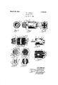
For a more complete understanding of my invent-ion referencemay behad tothe accompanying drawing in which like reference characters in the several views denote like parts and in which Fig. 1 is an elevation of the variable element of my invention;
Fig. 2 is a left end view of Fig. 1;-
Fig. 3 is a right end view of Fig. 1;
Fig. 4 is a sectional View along the line 44 of Fig. 1 to clearly illustrate the structure of the variable element.
Fig. 5 is'a plan view of the variable ele-- ment with the protective cover, actuating knob and terminal nuts removed;
Fig. 6 is a sectional view along the line 66 of Fig. 3;
Fig. 7 is a'right end view of Fig. 6;
Fig. 8 is a left end'view of'Fig. 6;
Fig. 9 is a sectional view along. the line 9-9 of Fig. 5 and Fig. 10 is a sectional view along the line 1()10-of Fig. 5.
Referring nowmore in detail to my inven tion as illustrated in the accompanying drawing the variable element of my invention comprises a spherically shaped rotor element 2 provided with a central orifice- 3 at right angles to its rotating axes. The coil or winding 4 of the rotor element is wound upon the spherical surface of the rotor 2 and the respective-terminal ends 5 and f the rotor winding 4 are lead to suitable terminals as will presently be described. The cylindrical member A which supports the stationary or stator windings 7 and 8 and also rotatably supports the rotor element Q'andits winding 4 comprises a pair of semi-circular members 9 and 10, which are fastened together to form the cylindrical member A by means of screws 11, which pass through aligned openings 12 in the. respective semi-circular members 9. and 10, and nuts 13 which have screw threaded engagement with the screws 11. countersunk orifices 14in the semi-circular members 9 and 10 are provided in which the heads ofthe screws 11. and the nuts 13 rest. The plane face 15 of the semi-circular memher 9 is provided with a concave portion 16 and the plane face 17 of the semi-circular member 10 is also provided with a concave portion 18 and these concave portions 16 and 18 in the faces 15and 17 of the semi-circular members 9'and 10 are in alignment or match and when the semi-circular members 9and 10. are secured together they form a till spherical opening 30. A pair of coils or windings 7 6 are shaped to contorm with the spherical surfaces of the concave portions 16 and 18 in the semi-circular memhere 9 and 10 and rest therein and are held in position by means oi suitable adhesive liquid such as collodion, which when dry permits the windings 'i' and 8 to adhere to the spherical surfaces of the concave portions 16 and 16. The respective terminal ends 21 and 22 ot' the windings 7 and 8 are lead to suitable terminals as will presently be described. 7
A pair oi shai'ts 28 and are provided for rotatably supporting the rotor element 2 as a whole in the spherical opening 30 formed by the two concave portions 16 and 18 in the semi-circular members 9 and 10. The rotor element 2 is provided with an orifice 25 which is slightly smaller than the diameter of the shaft 28 so as to produce a force lit for the shalt in the orifice 25. The rotor element 2 is also provided with an orifice 26 diametrically opposite the orifice 25 and the shaft 24 which is tubular in term is of suiteble insulation material and is slightly larg i. in diameter than the orifice 26 so as to produce a force lit for the shaft 24 in the orifice 26. The semi-circular members 9 and 10 are provided with semi'circular recesses 27 and28 diametrically oppo site, the said recesses in each or the semicircular menilbers 9 and 10 forming an orifice of a size to permit the shaft 23 to extend theret-hrough, and the said recesses 28 'in each oil? the semi-circular members 9 and 10 form orifice 01" a size to permit the shaft 24 to extend therethrough. The orifices thus formed by the recesses 2? and 28 form bearings for the shafts 23 and 24 of the rotor element 2 when the same is rotated.
he rotor element 2 is adapted to rotate within the spherical opening 30 formed by the two concave portions 16 and 18 in the semi-circular members and when the members 9 and 10 are clamped together to form the cylindrical men'iber A and held in concentric relation with the spherical opening 80 by means of space washers 31 and 32 placed upon the respective shafts 23 and 24 between the rotor element 2 and the face the spherical opening 30. Suitable terminals 33 and 34 are provided for the terminal ends 5 and 6 ot the winding 4 ot the rotor element 2, Terminals and 36 are provided for the terminal ends 21 and 22 of the windings and 8. The winding 4 of the rotor element 2 is wound on the spherical surface on each side of the rib 3? ot the rotor element 2 and its inner ends are suit ably connected to form continuous winding 4 and its outer terminal, ends 5 and 6 of which pass thron 1 the hollow shaft 24 and re seen ed respectively to the terminals 33 l). and 34 The windings l9"- and which rest in the spherical opening have their inner ends connected to form a continuous winding, the outer ends 21 and 22 of which pass through suitable channels 40 and 41and are secured respectively to the terminals 35 and 36. The terminals 33, 34 35 and 36 are all similarly constructed and as the description of one will be typical oi? the other three thus by describing terminal 34 in detail the construction of the others will be apparent. The terminal 34 comprises a screw 42 the head of which rests in a countersunk orifice 43 in member 10, the body of which passes through an orifice 44 in the member 10. A terminal 34 is provided with a central orifice and is adapted to slip over the screw 42 and a nut 45 having threaded engagement with the screw 42 clamps the terminal 34 in position and holds the screw 42 in the orifice 44, the terminal end 6 of the winding 4 of the rotor element 2 being soldered to the terminal 34.
The rotor element 2 is adapted to be rotated within the spherical opening 30 through a fixed degree, which is set at 180 degrees and I provide stopping means for stopping the rotor 2 in its zero position and its extreme position which is through 180 degrees of rotation. The shalt 23 of the rotor element 2 has secured to it a pin 46 which rests in a semi-circular recess 47 of substantially a 180 degree are in the face 50 of the semi-circular member 9. As clearly illustrated in Fig. Sthc pin 46 rests in a notch 51 in the edge of the member 10, which acts as a stop to limit the rotation of the rotor element 2 in this direction. A notch 52 in the edge of the member 10 diametrically opposite the notch 51 serves as a stop to be engaged by the pin 46 to limit the ro tation of the rotor element 2 in this direction.
A cover or protective casing 55 cup shape in form is provided with a threaded stud 56 which is secured in a central orifice in the casing 55 by means of a suitable i'ipsetting operation. The stud .56 is provided with a central orifice 57 through which shaft 23 extends. lhe end face 170 of semi-circular members 9 and 10 is provided with a recessed portion which recessed portions form an annular recess 171 to contain the terminals 33, 345 35 and 36 and the retaining nuts 45. A cover plate 58 is provided with tour orifices 59 through which the screws 42 pass to enclose the variable clei'nent the said screws 42 being insulated from thecover plate 58 by means of the insulating bushings 60 which slip over the screws 42 and rest in the orifices 59 in said cover. The cover plate 58 is provided with a pair ol diametrically opposite tongues 61 which rest indiametrically opposite notches 62 in the edge of casing 58 to place the cover plate 58 flush with the edge of the casing 55. lVhen the cover 58 is in place as just described, a disc 63 of insulating material provided with four orifices 64 in alignment with the screws 42 permits the said disc 63 to be slipped over the screws 42 and nuts 65 threaded down on the screws 42 again-st the disc 63 secures the cover 58 and disc 63 in position, the said disc 63 insulating the nuts 65 from the cover 58. Thumb nuts 66 threaded on the protruding ends of the screws 42 serve as connection terminals for connection purposes with the external circuits in which the variable element of my invention is used.
The threaded stud 56 secured to the casing 55 permits the variable element to be adapted for panel mounting, as illustrated in Fig. 1. The threaded stud 56 passes through a suitable orifice in the panel '67 shown in dotted lines and a nut 68 having screwthreaded engagement with the threaded stud 56 which protrudes through the orifice in the panel 67 secures the variable element of my invention as a whole to the panel 67. A knob 69 for rotating the rotor element 2 through its degree of rotation is secured to the shaft 23 by means of a set screw 70 and an indicating arrow 71 suitably secured to the knob 69 indicates to the operator the degree of rotation of the rotor element. The variable element is also adapted for socket mounting, the casing 55 being provided with a pin 72 which is adapted to engage the bayonet slot in the socket and the thumb nuts 66 threaded on the screws &2 engage the respective spring members associated with the socket, as is well understood.
From the description it may be seen that I have devised a variable element which is small and compact in construction and which is readily adapted for use as a radio frequency transformer in which the rotor element winding is used as the primary of the transformer and the stator winding is used as the secondary winding of the transformer or vice versa.
While I have described a preferred embodiment of my invention it is readily apparent the changes and modifications will readily suggest themselves and I therefore aim to cover all such changes and modifications as come within the spirit and scope of the appended claims.
What I claim as new and desire to secure by United States Letters Patent is:
1. In a device of the character described including a pair of members comprising a stator element, a spherical member comprising a rotor element, shafts for supporting said rotor element, said pair of members having a pair of concave portions forming a spherical opening, said shafts supporting said rotor element in said spherical openin means adapted to support the whole in a socket and other means adapted to support the whole on a panel,
2. In a device of the character described including a pair of semi-cylindrical munbers comprising a stator element and a spherical member comprising a rotor element, shafts for said rotor element, said semi-cylindrical members having a pair of concave portions forming a spherical opening, hearings in said stator members for said. shafts for rotatably supporting said rotor element in said spherical opening, a windin on said rotor element and a winding on saiil stator element and terminal screws supported by said semi circular members for securing terminals thereto for connecting the terminal ends of said winding to said terminals, means adapted to support the whole in a socket and other means adapted to support the whole on a panel.
3. In a device of the characterdescribed including av pair of semi-cylindrical members comprising a stator element and aspher-ical member comprising a rotor element, shafts for said rotor element, said semi-cylindrical members having a pair of concave portions forming a spherical opening, means for securing. said semi-cylindrical members together to form a cylindrical member, bearings in said. semi-cylindrical members for said shaft for rotatably supporting said rotor element in said spherical opening and an enclosing casing for said cylindrical member and its supported rotor element, means adapted to support the whole in a socket and other means adapted to support the whole on a panel. I
4. In a device of the character described including a stator element comprising a pair of semi-cylindrical elements and a spherical member comprising a rotor elcment, said semi-cylindrical members having a pair of concave portions forming a spherical opening in said stator elements, and clamping means for securing said pair of semi-cylindrical members together to form a cylindrical stator member, shafts for said rotor element, bearings in said stator member for said shaft for rotatably supporting said rotor in said spherical opening, terminals for the terminal end of the windings of said rotor and stator windings secured to said stator member, an enclosing casing for said stator member and its supported rotor element, means cooperating with said enclosing casing to support the whole on a panel, a. cover plate for said casing and terminal extensions from said terminals extending through said cover plate for connecting said terminals to external circuits, said terminal extensions and means on said cover plate adapted to support the whole in a socket.
5. In a device of the character described including a pair of members comprising a stator element, a spherical member comprising a rotor element, shafts for supporting said rotor element, said pair of members having a pair of concave portions forming a spherical opening in said stator element, said shafts supporting said rotor element in said spherical opening, windings for said stator and rotor element, and terminals supported by said stator having leads connected to said windings means adapted to support the Whole in a socket and other means adapted to support the Whole on a panel.
6. In a device of the character described including a pair of members comprising a stator element, a spherical member comprising a rotor element, shafts for supporting said rotor element, said pair of members having a pair of concave portions forming a spherical opening in said stator element, said shafts supporting said rotor element in said spherical opening, a cover for said device, means associated With said cover for adapting the said device to be supported in a socket and other means adapted to support the Whole on a panel.
7. In a device of the character described including a pair of members comprising a stator element, a spherical member comprising a rotor element, shafts for supporting said rotor element, said pair of members having a pair of concave portions forming a spherical opening in said stator element, said shafts supporting said rotor element in said spherical opening, windings for said stator and rotor element, means adapted to support the Whole on a panel, terminals supported by said stator having leads connected to said windings, said terminals beingso situated that the device may fit into a mounting socket, and an enclosingcasing having a pin member, said pin member and said terminals adapted to support the Whole in said mounting socket.
Signed by me at Chicago, in the county 01" Cook and State of Illinois, this 28th day of January, 1924.
IVILLIAM KAISLINGJ
Priority Applications (1)
| Application Number | Priority Date | Filing Date | Title |
|---|---|---|---|
| US689434A US1663010A (en) | 1924-01-30 | 1924-01-30 | Variable element |
Applications Claiming Priority (1)
| Application Number | Priority Date | Filing Date | Title |
|---|---|---|---|
| US689434A US1663010A (en) | 1924-01-30 | 1924-01-30 | Variable element |
Publications (1)
| Publication Number | Publication Date |
|---|---|
| US1663010A true US1663010A (en) | 1928-03-20 |
Family
ID=24768448
Family Applications (1)
| Application Number | Title | Priority Date | Filing Date |
|---|---|---|---|
| US689434A Expired - Lifetime US1663010A (en) | 1924-01-30 | 1924-01-30 | Variable element |
Country Status (1)
| Country | Link |
|---|---|
| US (1) | US1663010A (en) |
Cited By (2)
| Publication number | Priority date | Publication date | Assignee | Title |
|---|---|---|---|---|
| US3052859A (en) * | 1960-01-25 | 1962-09-04 | Space Technology Lab Inc | Resolver type function generator |
| US3178600A (en) * | 1960-01-25 | 1965-04-13 | Thompson Ramo Wooldridge Inc | Motor structure including spherical windings |
-
1924
- 1924-01-30 US US689434A patent/US1663010A/en not_active Expired - Lifetime
Cited By (2)
| Publication number | Priority date | Publication date | Assignee | Title |
|---|---|---|---|---|
| US3052859A (en) * | 1960-01-25 | 1962-09-04 | Space Technology Lab Inc | Resolver type function generator |
| US3178600A (en) * | 1960-01-25 | 1965-04-13 | Thompson Ramo Wooldridge Inc | Motor structure including spherical windings |
Similar Documents
| Publication | Publication Date | Title |
|---|---|---|
| US2259628A (en) | Adjustable antenna unit | |
| TW201621203A (en) | Supporting device | |
| US2375309A (en) | High-frequency transformer | |
| US1663010A (en) | Variable element | |
| US2206250A (en) | Transformer | |
| US2961626A (en) | Adjustable potentiometer constructions | |
| US2439277A (en) | High-frequency coil | |
| US1595752A (en) | Variable inductance | |
| US882253A (en) | Coil-winding machine. | |
| US2688681A (en) | Squaring potentiometer | |
| US2142355A (en) | Combination plug-in resistor and switch | |
| US3155895A (en) | Coil assembly with threaded stem core | |
| US2883634A (en) | Limit stops for rotatable inductive electro-mechanical devices | |
| US3384295A (en) | Miniature electrical blower | |
| US2748387A (en) | Antenna structure | |
| JPH043660B2 (en) | ||
| US1651975A (en) | Variable condenser | |
| US1589416A (en) | Variable element | |
| US1551150A (en) | Electrical inductance apparatus | |
| US1445242A (en) | Variable inductance element | |
| US1750393A (en) | Variable condenser | |
| US2914276A (en) | Variable inductance device | |
| US3537051A (en) | Adjustable sliding brush transformer | |
| US1630873A (en) | Variometer | |
| US1217348A (en) | Variable electrical apparatus. |