US1663007A - Electric conductor support - Google Patents
Electric conductor support Download PDFInfo
- Publication number
- US1663007A US1663007A US274159A US27415919A US1663007A US 1663007 A US1663007 A US 1663007A US 274159 A US274159 A US 274159A US 27415919 A US27415919 A US 27415919A US 1663007 A US1663007 A US 1663007A
- Authority
- US
- United States
- Prior art keywords
- insulator
- clamp
- support
- ring
- arms
- Prior art date
- Legal status (The legal status is an assumption and is not a legal conclusion. Google has not performed a legal analysis and makes no representation as to the accuracy of the status listed.)
- Expired - Lifetime
Links
Images

Classifications
-
- H—ELECTRICITY
- H01—ELECTRIC ELEMENTS
- H01B—CABLES; CONDUCTORS; INSULATORS; SELECTION OF MATERIALS FOR THEIR CONDUCTIVE, INSULATING OR DIELECTRIC PROPERTIES
- H01B17/00—Insulators or insulating bodies characterised by their form
- H01B17/14—Supporting insulators
- H01B17/16—Fastening of insulators to support, to conductor, or to adjoining insulator
Definitions
- the clamping. means which I provide is intended to give a solid grip on the insu-- lator, the insulator being constructed so that the clamp may grip the same at either end for universal mounting purposes.
- This clamping means is formed of a circumferential member divided into more than two necte-d together by suitable clamping bolts.
- the clamp will be loose on the insulator and will be ineffective.
- the clamp of my invention being made of three or more parts, can be accurately fitted to the end of the insulator, even though considerable variation of size occur.
- my invention consists of a three part clamping ring adapted to be arranged around the insulator, in one instance at the base or secured end of the insulator and the other at the top or free end of the insulator, and adapted in each case to clamp and hold the insulator tightly without producing a crushing pressure or a fracturing strain at any point.
- My invention also includes means for accurately adjusting the height of the conductor supporting surface relatively to the height of the insulator in order to allow for the variation in height, both of the insuso lators and the insulator supports, when such supports form parts of larger structures.
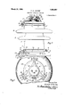
- Figure 1 is a side elevation of a conductor support shown partly in section
- Figure 2 is a top plan view of the sup- P i Y Figure 3 is a central vertical section of a 90 slightly modified form of conductor sup- Figure 4 is a horizontal sectional view' substantially on the line 4-4 of Figure 1.
- FIG. 5 represents a high ten- 95, sion insulator.
- This insulator is similar to other high tension insulators in that it ismade of glazed porcelain, glass or some similar high resistance and more or less' fragile material, and is provided with" one or more encircling and water shedding petticoats 6.
- the lower end 7 of the insulator is substantially the same diameter as the upper end 8 thereof, and I provide each end with a circumferential groove 9.
- This groove is round bottomed and preferably semi-cylindrical in .shape and beyond the groove 1 provide a similarly roundedclrcuniferential bead or flange 10.
- the grooves and beads at the two ends are substantially identical as to shape'and dimensions soas to facilitate an interchange of the top and bottom clamps for securing the insulator at either end to the supporting structure. I avoid any sharp corners or edges, joining all surfaces by means of smoot ly merging curved surfaces. 0
- base clamp 12 in the form of a ring adapted to encirclethe base of the insulator.
- ll divide-thering into three parts 1 1, which are identical with each other, so that they can be most cheaply manufactured as they can be all cast from a single pattern.
- each section'14c encircles substantially 120 of the base and has an inwardly projecting rib 15 at its upper edge adapted to enter the groove 9 in the insulator and engage the flange 10.
- Each section 14 is provided at its ends with outwardly extending clamping lugs 16 which are provided with bolt holes of sections.
- a two-part clamp each part of which must be substantially a half circle, may either be-relatively too small in diameter and will then engage the insulator at its ends,,or not properly enter thereon, or will be too large in diame- .ter and will then rock upon the insulator and not bind or claim) it properly, in either case producing localized pressure or strains which may tend to crack, fracture or break the insulator. I eliminate all of these difficulties by my three-part clamp.
- I preferably make each section slightly shorter than the one-third of the circumference of the 1nsulator with which the clamp contacts so as to provide ample space 18 between the adj acent clamping lugs 16 to permit the clamp to be contracted sufficiently to tightly clamp and hold the insulator even when the base of the insulator is considerably undersized. lit is obvious also that should the base of the insulator be oversized the three parts of the clamp can separate sufiiciently to receive the base and thatthe bolts 1'? will serve to secure the clamp, as a whole, upon the base of the insulator even when the adjacent lugs 16 cannot be brought into contact with each other.
- llt is also obvious that the base of the insulator can vary-considerably from its true circular shape and not prevent the three part clamp from properly engaging and holding same
- ll preferably form the lugs 16 slightly divergent so that as they are drawn together by .the bolts 17 they will first contact at" their holding the bottom of the insulator above and spaced from the adjacent surface of the support 11.
- Each of these foot lugs is provided with a bolt hole 20 for receiving a bolt 21 with which 1 secure the insulator to the support, the support 11 being provided with suitably spaced holes to receive the bolts 21.
- I connect the inner edge of each lug 19 to the ring 15 by the vertical web 22 ing device on the top clamp 13 I provide a conductor support 25 to which the conductor can be secured and provided with three .equ'i-circumferentially spaced arms 26, by which I mount the support 25 upon the clamping ring and hold it raised out of contact with the upper end of the insulator.
- the clamping bolts 28 thus serve to clamp the three-part ring upon the upper end '8 of the insulator .and also to rigidly carry the conductor support 25 in position upon a three-point support.
- the three-part ring is adjustable in size similar to the base ring to accommodate insulators which vary in size and also which vary from a true circular section and that I am enabled, by reason of the plurality of sections, to tightly clamp the ring upon the insulator and hold the upperring or support rigidly in position.
- the support 25 is made with its arms 26 extending outwardly sufiic iently far to ,permit thebolts 28 to be passed thru the clamping lugs 27 and the ends 29 of the arms before the clamp is contracted upon the insulator:
- the holes in said lugs and in the arms are made a relatively close fit upon the bolts 28.
- I provide an adjustable supporting member 31 which I secure to and upon the support 25 in such a manner that I can adjust the member 31 to position its upper flat surface 32 at various heights relatively to the insulator.
- I provide the member 31 in the form of a plug having an outer cylindrical threaded surface 33 and I make the support 25 in the form of a ring34 and I thread the, interior of the ring 34 to receive and hold the plug.
- the ring 34 is a split clamping ring adapted to be clamped tightly upon and support the member 31.
- I preferably arrange the split 35 midway betweentwo of the arms 26 so as best to permit the expansion and contraction of the ring 34 which ma be required.
- I provide the support mem er 31 with two spaced screw-threaded vertical to receive suitable bolts or screws for fastening the electric conductor or conductor clamp upon the member 31.
- I preferably make the vertical height of the member 31 equal to the vertical height of the ring 34 so that I can position the upper fiat surface of the member 31 close down to the upper edge of the ring .34.
- I can first clamp the base ring upon the insulator and secure the base ring upon the angle bar support by the bolts 21 and I can then secure the top clamp 13 upon the upper end of the insulator. I can then adjust the height of the plug 31 to bring its upper surface 32 into alignment with similar associated surfaces, then the member 31 can be tightly clamped in its ad justed position by means of the clamping bolt 37 of the ring 34.
- I have shown the insu-' lator 5 with the base clamp 12 secured to the top of the insulator and bolted to the under side of the metal support 38, and provided at its lower end with one of the clamp ing rings 13 which carries the conductor support.
- a conductor support 39 which is similar to the support shown in Figure 1 in that it is provided with three arms 40 for mounting it upon the ring 13, but instead of having an adjustable plug, I make this member solid at its outer end, providing it with threaded holes 41 for receiving bolts to clamp a, conductor to same.
- insulators which may vary considerably in dimensions without producing fracturing or breaking strains or pressure
- a peripheral member comprising three segments, said segments being constructed of relatively heavy non-resilient metal and having-inner contact faces adapted to fit into a groove in the insulator, screw threaded members connected to the ends of the segments tor-drawing adjacent ends of the segments together whereby the entire peripheral member-is put under tension and the segments areforced into the groove to hold the insulator under compression, and meansconnected to said peripheral member comprising three arms, said arms being drawn radially toward the center of the peripheral member as said screw threaded members are tightened.
- a peripheral member comprising three segments, said segments being constructed of relatively heavy non-resilient metal and having inner contact faces adapted to fit into a groove in the insulator, screw threaded members connected to the ends of the segments for drawing adjacent ends of the segments together whereby the" entire peripheral member is put under tension and the'segments are forced into the groove tov hold the insulator under compression, and meansconnected to said peripheral member comprising three arms, said arms being drawn radially toward the center of the peripheral member as said screw threaded members are tightened, said arms being rigidly joined together by a member lying over the end of the insulat0r.- p
- a peripheral member comprising three segments, said segment-s being constructed of relatively heavy non-resilient metal and having inner contact faces adapted to fit into v ments together whereby the entire peripha groove in the insulator, screw threaded members connected to the ends of the segments for drawing adjacent ends of the segeral member is put under tension and the segments are forced 1nto the groove to hold the insulator under compression, and means 1 connected to said peripheral member comnaeaoov prisin three arms, said arms being drawn radial y toward thecenter of the peripheral member as said screw threaded members are tightened, said arms being integrally joined together by a central member lying over the end of the insulator, said arms having holes through which said screw threaded members are passed.
- a cap fitting over the end of an insulator an insulator havin a rounded groove adjacent its end, a ring member consisting of three similar segments lying snugly in said groove, screw threaded means for drawing the ends of the segments together for shrinking or contracting the ring member into the groove and three connecting members extending between the cap and the ring, said connection members being drawn radially toward each other as the ring is contracted into the groove,
- an electric insulator consisting of a ring composed of three sections adapted to be bound around the upper end otthe insulator, and a supporting member adapted to be arranged above the top of the insulator, the ends of said sections spaced apart to receive arms projecting down from said support, and bolts clamping said sections upon the insulator and supporting said upper support.
- an insulator a fitting comprising a central'portion positioned at the end ofthe insulator, a plurality of yielding arms extending from said central portion along the side of the insulator end, a plurality of similar segments equal in number to the number of said arms and lying in the plane of the ends of said arms, and a plurality of tensionin'g members equal in number to said arms and interconnecting the ends of said segments to form a tension chain around said insulator and contract said segments and arms toward said insulator.
- a central member having a plurality of downwardly extending fingers for embracing the head of the insulator and segmental tension means including bolts, said tension means being adapted to bend the extending fingers inwardly as the clamp is drawn tight upon the insulator.
Description
March 20, 1928. 1,663,007
E. H. JACOBS ELECTRIC CONDUCTOR SUPPORT Filed Jan. 31, 1919 2 Sheets-Sheetl March 20, 1928.
E. H. JACOBS ELECTRIC CONDUCTOR SUPPORT Filed Jan. 51.. 1919 2 Sheets-SheetZ Ln n 55 Patented Mar. 281?, 'iQZS.
nears s'ra'rss eA'iNr caries;
ERNEST H. JACOBS, OF CHICAGO, ILLINOIS, ASS IGNOR TO ELECTRICAL ENGINEERS EQUIPMENT COMPANY, OF CHICAGO, ILLINOIS, A CORPORATION OF ILLINOIS.
ELECTRIC CONDUCTOR SUPPORT.
Application filed January 31, 1919. serial-No. 274,159.
When insulators were first used for supporting electric wires the low voltage employed and the lightweight of the conductors employed made the problem of insulating a relatively simple one. However, with the advent of high voltages and large capacity conductors and transmission lines extending through regions encountering great varieties of atmospheric conditions, the
problem of providing proper insulator support has become very dillicult. First of all it has been found extremely diflicult to provide a form of insulator which will not be too greatly effected by atmospheric conditions. This has been partially solved by the use oflarge sized porcelain petticoated insulators. These insulatorsare very expensive, particularly when it is considered that the breakage of a small part of one of the petticoats renders the entire insulator useless. T'hey must, therefore, be handled with the greatest care and yet they must be ,mounted in such position as to furnish a rigid and staunch support for the conductors. It is also desirable that the mounting of the same be made as simple as possible so that the same "will apply to as many situations as possible for the, purpose of interchangeability.
The clamping. means which I provide is intended to give a solid grip on the insu-- lator, the insulator being constructed so that the clamp may grip the same at either end for universal mounting purposes. This clamping means is formed of a circumferential member divided into more than two necte-d together by suitable clamping bolts.
The great practical difiiculty with this form .of clamping member is-that the insulators "are not uniform in size, withthe resultthat the clamp either cannot be gottenupon the 2 port; and
insulator, or if the insulator is slightly under size, the clamp will be loose on the insulator and will be ineffective.
The clamp of my invention, being made of three or more parts, can be accurately fitted to the end of the insulator, even though considerable variation of size occur.
By means of my invention I am able to provide a substantially universally adjustable insulator clamp for securing the insulators upon their'supports and similar ad justable clamps for securing the conductor support members to the free ends of the insulators.
Primarily my invention consists of a three part clamping ring adapted to be arranged around the insulator, in one instance at the base or secured end of the insulator and the other at the top or free end of the insulator, and adapted in each case to clamp and hold the insulator tightly without producing a crushing pressure or a fracturing strain at any point.
My invention also includes means for accurately adjusting the height of the conductor supporting surface relatively to the height of the insulator in order to allow for the variation in height, both of the insuso lators and the insulator supports, when such supports form parts of larger structures.
For a clear understanding of my invention, reference is made to the accompanying drawings, in which:
Figure 1 is a side elevation of a conductor support shown partly in section;
Figure 2 is a top plan view of the sup- P i Y Figure 3 is a central vertical section of a 90 slightly modified form of conductor sup- Figure 4 is a horizontal sectional view' substantially on the line 4-4 of Figure 1.
In said drawings 5 represents a high ten- 95, sion insulator. This insulator is similar to other high tension insulators in that it ismade of glazed porcelain, glass or some similar high resistance and more or less' fragile material, and is provided with" one or more encircling and water shedding petticoats 6. The lower end 7 of the insulator is substantially the same diameter as the upper end 8 thereof, and I provide each end with a circumferential groove 9. This groove is round bottomed and preferably semi-cylindrical in .shape and beyond the groove 1 provide a similarly roundedclrcuniferential bead or flange 10. The grooves and beads at the two ends are substantially identical as to shape'and dimensions soas to facilitate an interchange of the top and bottom clamps for securing the insulator at either end to the supporting structure. I avoid any sharp corners or edges, joining all surfaces by means of smoot ly merging curved surfaces. 0
1n conductor carrying structures of modern construction, it is usual to provide metal bars such as angle iron bars or I-beams to which to secure the insulators and in-the drawings 11 illustrates such a support. r In power and otherelectrlcal installations it is necessary to support relatively heavy and high tension electrical conductors by means of such angle iron structures and'msulated therefrom, and for this purpose the insulator 5 is secured upon the top of the angle iron and-a suitable-support is provided at the top of the insulator to or upon'which the conductor can be fastened. '1 provide the base clamp 12 and the top clamp or support 13..
1 make the base clamp 12 in the form of a ring adapted to encirclethe base of the insulator. ll divide-thering into three parts 1 1, which are identical with each other, so that they can be most cheaply manufactured as they can be all cast from a single pattern.
'Each section'14c encircles substantially 120 of the base and has an inwardly projecting rib 15 at its upper edge adapted to enter the groove 9 in the insulator and engage the flange 10. Each section 14: is provided at its ends with outwardly extending clamping lugs 16 which are provided with bolt holes of sections.
for receiving clamping bolts 17 by which the three sections can be bound tightlyaround and .upon thebase of the insulator. It will be noted that the several sections thus have maximumcontacting areas with the insulator and are thus prevented from producing fracturing or breakin pressure upon the insulator at any point. 1 prefer a three part clamp to one of more sections, as I obtain all the 'benefits of the universally adjustable clamp with the smallest number It is obvious that a two-part clamp, each part of which must be substantially a half circle, may either be-relatively too small in diameter and will then engage the insulator at its ends,,or not properly enter thereon, or will be too large in diame- .ter and will then rock upon the insulator and not bind or claim) it properly, in either case producing localized pressure or strains which may tend to crack, fracture or break the insulator. I eliminate all of these difficulties by my three-part clamp. I preferably make each section slightly shorter than the one-third of the circumference of the 1nsulator with which the clamp contacts so as to provide ample space 18 between the adj acent clamping lugs 16 to permit the clamp to be contracted sufficiently to tightly clamp and hold the insulator even when the base of the insulator is considerably undersized. lit is obvious also that should the base of the insulator be oversized the three parts of the clamp can separate sufiiciently to receive the base and thatthe bolts 1'? will serve to secure the clamp, as a whole, upon the base of the insulator even when the adjacent lugs 16 cannot be brought into contact with each other. llt is also obvious that the base of the insulator can vary-considerably from its true circular shape and not prevent the three part clamp from properly engaging and holding same As best shown in Figure 4: ll preferably form the lugs 16 slightly divergent so that as they are drawn together by .the bolts 17 they will first contact at" their holding the bottom of the insulator above and spaced from the adjacent surface of the support 11.. Each of these foot lugs is provided with a bolt hole 20 for receiving a bolt 21 with which 1 secure the insulator to the support, the support 11 being provided with suitably spaced holes to receive the bolts 21. 1- connect the inner edge of each lug 19 to the ring 15 by the vertical web 22 ing device on the top clamp 13 I provide a conductor support 25 to which the conductor can be secured and provided with three .equ'i-circumferentially spaced arms 26, by which I mount the support 25 upon the clamping ring and hold it raised out of contact with the upper end of the insulator.
The three sections 24 of the upper clamp 13, like those of the base clamp 12, are identical with each other and are provided at their ends with outwardly-projecting bolt lugs 27 provided with holes for receiving the clampenough shorter than one-third of the cir-= cumference of the insulator where the clamp is secured, so that I separate the adjacent ends of the sections far enough to receive the lower free ends 29 of the arms 26 between them. I provide these lower ends 29 with bolt holes 30 to receive the clamping bolts 28 and by this means I carry the conductor support 25. The clamping bolts 28 thus serve to clamp the three-part ring upon the upper end '8 of the insulator .and also to rigidly carry the conductor support 25 in position upon a three-point support. It will now be understood that the three-part ring is adjustable in size similar to the base ring to accommodate insulators which vary in size and also which vary from a true circular section and that I am enabled, by reason of the plurality of sections, to tightly clamp the ring upon the insulator and hold the upperring or support rigidly in position. i
The support 25 is made with its arms 26 extending outwardly sufiic iently far to ,permit thebolts 28 to be passed thru the clamping lugs 27 and the ends 29 of the arms before the clamp is contracted upon the insulator: The holes in said lugs and in the arms are made a relatively close fit upon the bolts 28. When the bolts 28 are drawn up to contract the three part clamp upon the insulator, the ends 29 of the arms 26' will be drawn radially inwardly thereby not only clamping the three part ring upon the insulator but also firmly clamping the support 25.
In order to provide a suitable connection upon which to secure a conductor or conductor clamp and to allow for a vertical adjustment of supporting surface to align same with associated supports, I provide an adjustable supporting member 31 which I secure to and upon the support 25 in such a manner that I can adjust the member 31 to position its upper flat surface 32 at various heights relatively to the insulator. Preferably I provide the member 31 in the form of a plug having an outer cylindrical threaded surface 33 and I make the support 25 in the form of a ring34 and I thread the, interior of the ring 34 to receive and hold the plug. Torigidly clamp the plug 31 in the ring 34 I split or out the ring 34 at one point, 35, of its circumference, and I provide its ends with outwardly extending clamping lugs 36 which I provide with holes to receive the clamping bolt 37. In'other words, the ring 34 is a split clamping ring adapted to be clamped tightly upon and support the member 31.
I preferably arrange the split 35 midway betweentwo of the arms 26 so as best to permit the expansion and contraction of the ring 34 which ma be required. I provide the support mem er 31 with two spaced screw-threaded vertical to receive suitable bolts or screws for fastening the electric conductor or conductor clamp upon the member 31. As shown, I preferably make the vertical height of the member 31 equal to the vertical height of the ring 34 so that I can position the upper fiat surface of the member 31 close down to the upper edge of the ring .34.
It will now be clear that in installing electrical conductor supports in accordance with my invention I can first clamp the base ring upon the insulator and secure the base ring upon the angle bar support by the bolts 21 and I can then secure the top clamp 13 upon the upper end of the insulator. I can then adjust the height of the plug 31 to bring its upper surface 32 into alignment with similar associated surfaces, then the member 31 can be tightly clamped in its ad justed position by means of the clamping bolt 37 of the ring 34. I
It is sometimes necessary to mount the insulators upon the under side instead of the top of the supporting structure and in Figure 3 I have shown such an adaptation of my invention. For this purpose I make the two ends of the insulator 5, as described,
duplicates of each other, as to the grooves 9 and flanges 10, so thatthe clamps 12 and 13 -can be used interchangeably thereon.
In said Figure 3 I have shown the insu-' lator 5 with the base clamp 12 secured to the top of the insulator and bolted to the under side of the metal support 38, and provided at its lower end with one of the clamp ing rings 13 which carries the conductor support. In this instance I have shown a conductor support 39 which is similar to the support shown in Figure 1 in that it is provided with three arms 40 for mounting it upon the ring 13, but instead of having an adjustable plug, I make this member solid at its outer end, providing it with threaded holes 41 for receiving bolts to clamp a, conductor to same.
My improved clamps, as shown, are cheap to manufacture, the sections of the rings being duplicates of each other, and the ma-' chine work beingrecluced to a minimum;
also they will tightly clamp and hold insulators which may vary considerably in dimensions without producing fracturing or breaking strains or pressure, and I am enabled to provide a series of supports for holding or supporting conductors or other electrically charged devices which can be arranged at a common level even though the several insulators themselves or their supports vary as to height among themselves.
It will also now be understood that I am enabled to use insulators which would other wise have to be discarded by reason of their variation from standard dimensions, or by reason of their distortion from standard iii!) shape also that in providing a complete line a peripheral member comprising three segments, said segments being constructed of relatively heavy non-resilient metal and having-inner contact faces adapted to fit into a groove in the insulator, screw threaded members connected to the ends of the segments tor-drawing adjacent ends of the segments together whereby the entire peripheral member-is put under tension and the segments areforced into the groove to hold the insulator under compression, and meansconnected to said peripheral member comprising three arms, said arms being drawn radially toward the center of the peripheral member as said screw threaded members are tightened.
2. In a means for gripping an insulator, a peripheral member comprising three segments, said segments being constructed of relatively heavy non-resilient metal and having inner contact faces adapted to fit into a groove in the insulator, screw threaded members connected to the ends of the segments for drawing adjacent ends of the segments together whereby the" entire peripheral member is put under tension and the'segments are forced into the groove tov hold the insulator under compression, and meansconnected to said peripheral member comprising three arms, said arms being drawn radially toward the center of the peripheral member as said screw threaded members are tightened, said arms being rigidly joined together by a member lying over the end of the insulat0r.- p
'3. In a means for gripping an insulator, a peripheral member comprising three segments, said segment-s being constructed of relatively heavy non-resilient metal and having inner contact faces adapted to fit into v ments together whereby the entire peripha groove in the insulator, screw threaded members connected to the ends of the segments for drawing adjacent ends of the segeral member is put under tension and the segments are forced 1nto the groove to hold the insulator under compression, and means 1 connected to said peripheral member comnaeaoov prisin three arms, said arms being drawn radial y toward thecenter of the peripheral member as said screw threaded members are tightened, said arms being integrally joined together by a central member lying over the end of the insulator, said arms having holes through which said screw threaded members are passed.
42. In combination, a cap fitting over the end of an insulator, an insulator havin a rounded groove adjacent its end, a ring member consisting of three similar segments lying snugly in said groove, screw threaded means for drawing the ends of the segments together for shrinking or contracting the ring member into the groove and three connecting members extending between the cap and the ring, said connection members being drawn radially toward each other as the ring is contracted into the groove,
5. The improvements herein described,
comprising a clamp tor the upper end of an electric insulator consisting of a ring composed of three sections adapted to be bound around the upper end otthe insulator, and a supporting member adapted to be arranged above the top of the insulator, the ends of said sections spaced apart to receive arms projecting down from said support, and bolts clamping said sections upon the insulator and supporting said upper support.
6. In combination, an insulator, a fitting comprising a central'portion positioned at the end ofthe insulator, a plurality of yielding arms extending from said central portion along the side of the insulator end, a plurality of similar segments equal in number to the number of said arms and lying in the plane of the ends of said arms, and a plurality of tensionin'g members equal in number to said arms and interconnecting the ends of said segments to form a tension chain around said insulator and contract said segments and arms toward said insulator.
7. In a clamp for an insulator, a central member having a plurality of downwardly extending fingers for embracing the head of the insulator and segmental tension means including bolts, said tension means being adapted to bend the extending fingers inwardly as the clamp is drawn tight upon the insulator.
In Witness whereof I hereunto subscribe my name this 20 day of January, A. D. 191.9.
ERNEST H. JACOBS.
Priority Applications (1)
| Application Number | Priority Date | Filing Date | Title |
|---|---|---|---|
| US274159A US1663007A (en) | 1919-01-31 | 1919-01-31 | Electric conductor support |
Applications Claiming Priority (1)
| Application Number | Priority Date | Filing Date | Title |
|---|---|---|---|
| US274159A US1663007A (en) | 1919-01-31 | 1919-01-31 | Electric conductor support |
Publications (1)
| Publication Number | Publication Date |
|---|---|
| US1663007A true US1663007A (en) | 1928-03-20 |
Family
ID=23047026
Family Applications (1)
| Application Number | Title | Priority Date | Filing Date |
|---|---|---|---|
| US274159A Expired - Lifetime US1663007A (en) | 1919-01-31 | 1919-01-31 | Electric conductor support |
Country Status (1)
| Country | Link |
|---|---|
| US (1) | US1663007A (en) |
Cited By (1)
| Publication number | Priority date | Publication date | Assignee | Title |
|---|---|---|---|---|
| US3104278A (en) * | 1960-02-15 | 1963-09-17 | Ohio Brass Co | Electrical apparatus housing |
-
1919
- 1919-01-31 US US274159A patent/US1663007A/en not_active Expired - Lifetime
Cited By (1)
| Publication number | Priority date | Publication date | Assignee | Title |
|---|---|---|---|---|
| US3104278A (en) * | 1960-02-15 | 1963-09-17 | Ohio Brass Co | Electrical apparatus housing |
Similar Documents
| Publication | Publication Date | Title |
|---|---|---|
| US1663007A (en) | Electric conductor support | |
| US976879A (en) | Base for poles or posts. | |
| KR102089508B1 (en) | connection structure for overhead electric power line | |
| US1915838A (en) | Insulator | |
| US2207522A (en) | Concentric conductor transmission line | |
| US1928622A (en) | Conductor and ground wire support | |
| US1755971A (en) | Insulator | |
| US1869877A (en) | Pole fitting | |
| US1715478A (en) | Cap for insulators | |
| US1230992A (en) | Lamp-support. | |
| US1409927A (en) | Bus-bar support | |
| CN207529731U (en) | A kind of insulation support device | |
| KR102075824B1 (en) | Supporting unit for switch | |
| US678042A (en) | Rack-insulator. | |
| US1388217A (en) | Insulator | |
| US1802743A (en) | Transmission-line device | |
| US2260917A (en) | Insulator pin | |
| US1458756A (en) | Strain insulator | |
| US1492714A (en) | Insulator clamp | |
| US2277212A (en) | Joint for electrical conductors | |
| US1378519A (en) | Suspension for trolley-wires and the like | |
| US2007141A (en) | Grading ring | |
| US917031A (en) | Insulator for high-tension transmission-lines. | |
| US1643943A (en) | Insulator support | |
| US1702235A (en) | System of line insulation and insulators therefor |