US1663003A - Conveyer roller - Google Patents
Conveyer roller Download PDFInfo
- Publication number
- US1663003A US1663003A US12563A US1256325A US1663003A US 1663003 A US1663003 A US 1663003A US 12563 A US12563 A US 12563A US 1256325 A US1256325 A US 1256325A US 1663003 A US1663003 A US 1663003A
- Authority
- US
- United States
- Prior art keywords
- roller
- shaft
- tubular member
- cones
- cups
- Prior art date
- Legal status (The legal status is an assumption and is not a legal conclusion. Google has not performed a legal analysis and makes no representation as to the accuracy of the status listed.)
- Expired - Lifetime
Links
Images
Classifications
-
- F—MECHANICAL ENGINEERING; LIGHTING; HEATING; WEAPONS; BLASTING
- F16—ENGINEERING ELEMENTS AND UNITS; GENERAL MEASURES FOR PRODUCING AND MAINTAINING EFFECTIVE FUNCTIONING OF MACHINES OR INSTALLATIONS; THERMAL INSULATION IN GENERAL
- F16C—SHAFTS; FLEXIBLE SHAFTS; ELEMENTS OR CRANKSHAFT MECHANISMS; ROTARY BODIES OTHER THAN GEARING ELEMENTS; BEARINGS
- F16C13/00—Rolls, drums, discs, or the like; Bearings or mountings therefor
- F16C13/02—Bearings
-
- F—MECHANICAL ENGINEERING; LIGHTING; HEATING; WEAPONS; BLASTING
- F16—ENGINEERING ELEMENTS AND UNITS; GENERAL MEASURES FOR PRODUCING AND MAINTAINING EFFECTIVE FUNCTIONING OF MACHINES OR INSTALLATIONS; THERMAL INSULATION IN GENERAL
- F16C—SHAFTS; FLEXIBLE SHAFTS; ELEMENTS OR CRANKSHAFT MECHANISMS; ROTARY BODIES OTHER THAN GEARING ELEMENTS; BEARINGS
- F16C19/00—Bearings with rolling contact, for exclusively rotary movement
- F16C19/54—Systems consisting of a plurality of bearings with rolling friction
- F16C19/546—Systems with spaced apart rolling bearings including at least one angular contact bearing
- F16C19/547—Systems with spaced apart rolling bearings including at least one angular contact bearing with two angular contact rolling bearings
Definitions
- My invention relates to conveyor rollers and has for its principal objectto produce a roller for belt and other conveyer that will be extremely light in construction and that will be easily adapted for use WitlKTOllGl bearings.
- the invention consists principally in providing a hollow conveyer roller with an inner tubular member-that provides a chamber within which roller bearings may be mounted, said tubular member having flanged end portions preferably in the form of spoke- .likemembers, that are secured to the roller,
- the invention further consists in the conveyer roller and in the parts and combinations of parts hereinafter described and claimed.
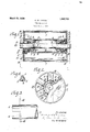
- Fig. 1 is'a longitudinal sectional view of a conveyor roller embodying my invention
- Fig 2 is an end view
- Fig. 3 is a diagrammatic view illustrating the process of forming the spoke-like members on the ends of the tubular member.
- Fi 4 is a fragmentary sectional view on the line 4-4: of Fig. 1 showing the abutments on the roller shaft for the roller hearing cone.
- a hollow conveyer roller 1 for a belt or other 'conveyer is rotatably mounted on a shaft 2.
- a tulugs or shoulders 5 that constitute abut-' ments for the cones 6 or inner bearing mem bers of conicalroller bearings.
- the conical rollers 7 are disposed on said cones 6; and the cups 8 or outer bearing members therefor are disposed'in the bore of.the tubular 4 member 3. .
- Annular adjusting nuts 9 are threaded into the ends of the bore of the tubular member 3 and abut against the endsof the respective cups 8. The positions of the cups may be ad usted by rotating said nuts 9.
- the nuts are provided with holes 10 therethrough at intervals and the tubular member 3 is provided with one or more holes 11 at each end as at the juncture, between the body portion of the tube and the end.
- the adjusting nuts 9 may be bular shell member 3 that has end portions held in position by 'means of wires 12 or cotter pins 13 passing through one of the holes insthe adjusting nut and a hole in a tubular member.
- the tubular inner member 3 is made by slotting the ends-of a cylindrical 4 tube as shown in Figure 3.
- the end pieces .4 .between the slots are then bent up substantiallyperpendicular with the axis of the tube to form spoke-like members 4;.
- the as tubular member is then inserted in the. roller and the ends of the spokes 4 secured'to the roller as by welding as indicated at 14 in the drawing.
- an annular washer 15 is. secured in each end of the, roller,as by being, welded to a plurality of s okes 4.
- the opening in the washer is s ightly'larger than the shaft 2, whereb the washer excludes dirt from the roller. he washer is easily removed when it is desired to adjust a bearing.
- the shaft is provided with a bore. 16 through part of its length, permitting entry of lubricant to the bearings and suitable lubricant retainers 17 are provided.
- a shaft an elongated hollow roller rotatably'anounted on said shaft, an elongated tubular member in said roller, and antifriction bearings interposed between said tubular member and said shaft, said tubular member having radially extending spoke members at its ends made by bending the portions between slots in said tubular memer that extend longitudinally from the we ends thereof, and said spoke members being secured to said roller, at the end portions thereof.
- a shaft an elongated hollow roller rot-atably mounted on said shaft,.an elongated tubular member in said roller, and antifriction bearings inter osed. between said tubular member and said shaft, said tubular member having'radially extending spoke members at its ends made by bending the no in each end of said roller abutting against said spoke members, and substantially filling the space between the inner periphery of said roller and said shaft.
- a shaft an elongated hollow roller rotatably mounted on said shaft, an elongated tubular member in said roller, and antifriction bearings interposed between said.
- tubular member and said shaft said tubular member having radially extending spoke members made by bending the portions between slots in said'tubular member that extend longitudinally from the ends thereof and said spoke members beingsecured to said roller, and an annular washer in each end of said roller abutting against said spoke members and secured to a plurality thereof, and substantially filling the space between the inner periphery of said roller and said shaft.
- a shaft a hollow roller rotatably mounted on said shaft, roller bearing cups in the ends of said roller, roller bearing cones on said shaft and conical rollers interposed between said cups and cones, said shaft having upstandin spaced lugs struck up from the metal 0 the shaft, against which lugs said cones abut.
- a shaft a hollowroller rotatably mounted on said shaft, roller bearing cups ed on said shaft, an elongated tubular member extending through said roller, roller bearing cups in the ends of said tubular member, roller bearing cones on said shaft, conical rollers interposed between said cups and cones, said shaft having upstandingspaced lugs struck up from the metal of the shaft, against-which lugs said cones abut, and adjusting nuts for said bearing cups threaded into the ends of said tubular member.
- a shaft an elongated hollow roller rotatably mounted on said shaft, an elongated tubular member extending through said roller, roller bearing cups in the ends of said tubular member, roller bearing cones on said shaft, conical rollers interposed between said cups and cones, said shaft having upstandin lugs against which said cones abut, and ad]ust1ng nuts for said bearing cups threaded into the ends of said tubular member, said tubular member having radially extending spoke members at its ends made by bending the portions between slots in said tubular member that extend longitudinally from the ends thereof and said spoke members being secured to said roller at the end portions thereof. Signed at Canton, Ohio, this 17th day of February, 1925.
Landscapes
- Engineering & Computer Science (AREA)
- General Engineering & Computer Science (AREA)
- Mechanical Engineering (AREA)
- Rollers For Roller Conveyors For Transfer (AREA)
Description
March 20, 1928.
G. W. C URTIS CONVEYER ROLLER Filed March 2, 1925 my; ATTORNEYS,
Patented Mar. 20, 1928.
UNITED STATES 1.66am PATENT OFFICE-.7
ononon w. CURTIS, or CANTON, oHIo, ASSIGNOB ro 'rrm rmxnn ROLLER IBEABING COMPANY, 01? CANTON, OHIO, A. CORPORATION. OEQHIO.
oonvnxan Roman.
Application filed mm 2, 1925. Serial No. 12,563.
My invention relates to conveyor rollers and has for its principal objectto produce a roller for belt and other conveyer that will be extremely light in construction and that will be easily adapted for use WitlKTOllGl bearings.
The invention consists principally in providing a hollow conveyer roller with an inner tubular member-that provides a chamber within which roller bearings may be mounted, said tubular member having flanged end portions preferably in the form of spoke- .likemembers, that are secured to the roller,
asgby. welding. The invention further consists in the conveyer roller and in the parts and combinations of parts hereinafter described and claimed.
. In the accompanying drawing which forms part ofthis specification and wherein like reference numerals indicate like parts wherever they occur,
Fig. 1 is'a longitudinal sectional view of a conveyor roller embodying my invention;
Fig 2 is an end view;
Fig. 3 is a diagrammatic view illustrating the process of forming the spoke-like members on the ends of the tubular member; and
A hollow conveyer roller 1 for a belt or other 'conveyer is rotatably mounted on a shaft 2. Mounted in the roller 1 is a tulugs or shoulders 5 that constitute abut-' ments for the cones 6 or inner bearing mem bers of conicalroller bearings. The conical rollers 7 are disposed on said cones 6; and the cups 8 or outer bearing members therefor are disposed'in the bore of.the tubular 4 member 3. .Annular adjusting nuts 9 are threaded into the ends of the bore of the tubular member 3 and abut against the endsof the respective cups 8. The positions of the cups may be ad usted by rotating said nuts 9. Preferably the nuts are provided with holes 10 therethrough at intervals and the tubular member 3 is provided with one or more holes 11 at each end as at the juncture, between the body portion of the tube and the end. The adjusting nuts 9 may be bular shell member 3 that has end portions held in position by 'means of wires 12 or cotter pins 13 passing through one of the holes insthe adjusting nut and a hole in a tubular member.
Preferably the tubular inner member 3 is made by slotting the ends-of a cylindrical 4 tube as shown in Figure 3. The end pieces .4 .between the slots are then bent up substantiallyperpendicular with the axis of the tube to form spoke-like members 4;. The as tubular member is then inserted in the. roller and the ends of the spokes 4 secured'to the roller as by welding as indicated at 14 in the drawing.
Preferably" an annular washer 15 is. secured in each end of the, roller,as by being, welded to a plurality of s okes 4. The opening in the washer is s ightly'larger than the shaft 2, whereb the washer excludes dirt from the roller. he washer is easily removed when it is desired to adjust a bearing.
The shaft is provided with a bore. 16 through part of its length, permitting entry of lubricant to the bearings and suitable lubricant retainers 17 are provided.
The above described construction has nu merous advantages. It is light and" at the same time-strong'and durable. It is easily made and assembled and it is especially .without departing from the invention and I do not wish to be limited to the precise construction shown.
What I claim is:
1. ,A shaft, an elongated hollow roller rotatably'anounted on said shaft, an elongated tubular member in said roller, and antifriction bearings interposed between said tubular member and said shaft, said tubular member having radially extending spoke members at its ends made by bending the portions between slots in said tubular memer that extend longitudinally from the we ends thereof, and said spoke members being secured to said roller, at the end portions thereof.
2. A shaft, an elongated hollow roller rot-atably mounted on said shaft,.an elongated tubular member in said roller, and antifriction bearings inter osed. between said tubular member and said shaft, said tubular member having'radially extending spoke members at its ends made by bending the no in each end of said roller abutting against said spoke members, and substantially filling the space between the inner periphery of said roller and said shaft.
3. A shaft, an elongated hollow roller rotatably mounted on said shaft, an elongated tubular member in said roller, and antifriction bearings interposed between said.
tubular member and said shaft, said tubular member having radially extending spoke members made by bending the portions between slots in said'tubular member that extend longitudinally from the ends thereof and said spoke members beingsecured to said roller, and an annular washer in each end of said roller abutting against said spoke members and secured to a plurality thereof, and substantially filling the space between the inner periphery of said roller and said shaft.
4. An elongated hollow conveyer roller and an elongated tubular shell extending therethrough, the ends of said shell being slit longitudinally and bent radially thereby forming outwardly extending spoke members Whose ends are welded to the inner surface of said roller near the ends thereof.
5. An elongated hollow conveyer. roller and an elongated tubular shell extending therethrough, the ends of said shell being slit longitudinally and bent radially thereby forming outwardly extending spoke members whose ends are welded to the inner surface of said roller, and an annular washer in each end of said roller abutting against said spoke members and closing the end of said roller.
6. A shaft, a hollow roller rotatably mounted on said shaft, roller bearing cups in the ends of said roller, roller bearing cones on said shaft and conical rollers interposed between said cups and cones, said shaft having upstandin spaced lugs struck up from the metal 0 the shaft, against which lugs said cones abut.
7. A shaft, a hollowroller rotatably mounted on said shaft, roller bearing cups ed on said shaft, an elongated tubular member extending through said roller, roller bearing cups in the ends of said tubular member, roller bearing cones on said shaft, conical rollers interposed between said cups and cones, said shaft having upstandingspaced lugs struck up from the metal of the shaft, against-which lugs said cones abut, and adjusting nuts for said bearing cups threaded into the ends of said tubular member.
9. A shaft, an elongated hollow roller rotatably mounted on said shaft, an elongated tubular member extending through said roller, roller bearing cups in the ends of said tubular member, roller bearing cones on said shaft, conical rollers interposed between said cups and cones, said shaft having upstandin lugs against which said cones abut, and ad]ust1ng nuts for said bearing cups threaded into the ends of said tubular member, said tubular member having radially extending spoke members at its ends made by bending the portions between slots in said tubular member that extend longitudinally from the ends thereof and said spoke members being secured to said roller at the end portions thereof. Signed at Canton, Ohio, this 17th day of February, 1925.
GEORGE W. CURTIS.
Priority Applications (1)
| Application Number | Priority Date | Filing Date | Title |
|---|---|---|---|
| US12563A US1663003A (en) | 1925-03-02 | 1925-03-02 | Conveyer roller |
Applications Claiming Priority (1)
| Application Number | Priority Date | Filing Date | Title |
|---|---|---|---|
| US12563A US1663003A (en) | 1925-03-02 | 1925-03-02 | Conveyer roller |
Publications (1)
| Publication Number | Publication Date |
|---|---|
| US1663003A true US1663003A (en) | 1928-03-20 |
Family
ID=21755551
Family Applications (1)
| Application Number | Title | Priority Date | Filing Date |
|---|---|---|---|
| US12563A Expired - Lifetime US1663003A (en) | 1925-03-02 | 1925-03-02 | Conveyer roller |
Country Status (1)
| Country | Link |
|---|---|
| US (1) | US1663003A (en) |
Cited By (3)
| Publication number | Priority date | Publication date | Assignee | Title |
|---|---|---|---|---|
| US3001842A (en) * | 1958-09-24 | 1961-09-26 | Chrysler Corp | Differential bearing assembly |
| US3011665A (en) * | 1958-12-04 | 1961-12-05 | Joseph H Wise | Material handling apparatus |
| US20040104102A1 (en) * | 2002-11-29 | 2004-06-03 | Itoh Electric Company Limited | Roller device and a method of making same |
-
1925
- 1925-03-02 US US12563A patent/US1663003A/en not_active Expired - Lifetime
Cited By (4)
| Publication number | Priority date | Publication date | Assignee | Title |
|---|---|---|---|---|
| US3001842A (en) * | 1958-09-24 | 1961-09-26 | Chrysler Corp | Differential bearing assembly |
| US3011665A (en) * | 1958-12-04 | 1961-12-05 | Joseph H Wise | Material handling apparatus |
| US20040104102A1 (en) * | 2002-11-29 | 2004-06-03 | Itoh Electric Company Limited | Roller device and a method of making same |
| US6755299B2 (en) * | 2002-11-29 | 2004-06-29 | Itaoh Electric Company Limited | Roller device and a method of making same |
Similar Documents
| Publication | Publication Date | Title |
|---|---|---|
| US2622934A (en) | Hub construction for wheels | |
| WO2005116466A1 (en) | Tapered roller bearing for a wheel | |
| US1663003A (en) | Conveyer roller | |
| US1325113A (en) | Ball-bearing | |
| US11230143B2 (en) | Hub-bearing assembly for vehicles | |
| CN103089820B (en) | For the radial direction retainer of cylindrical rolling element, especially needle bearing cage | |
| US1871149A (en) | Roller bearing construction | |
| US2063587A (en) | Bearing cage | |
| US1426578A (en) | Chables i | |
| WO2015197059A1 (en) | Cage for a rolling bearing, rolling bearing and planetary gear bearing | |
| DE102013222448B4 (en) | Wheel, in particular for a motor vehicle | |
| US488539A (en) | Hubert claus | |
| US3428376A (en) | Spoke-type wheel | |
| US2010108A (en) | Roller bearing | |
| DE102017105523B4 (en) | hub | |
| JP5948876B2 (en) | Tapered roller bearing and wheel bearing device | |
| US1194917A (en) | of port dover | |
| US1923799A (en) | Bearing construction | |
| US1837480A (en) | Construction for rollers and the like | |
| US1789325A (en) | Conveyer roll | |
| US2618519A (en) | Idler roller assembly | |
| US1651073A (en) | Combined radial and thrust bearing | |
| US2230912A (en) | Inboard axle construction | |
| US1722143A (en) | Bearing-removing process | |
| US1242277A (en) | Wheel-hub. |