US165839A - Improvement in land-rollers - Google Patents
Improvement in land-rollers Download PDFInfo
- Publication number
- US165839A US165839A US165839DA US165839A US 165839 A US165839 A US 165839A US 165839D A US165839D A US 165839DA US 165839 A US165839 A US 165839A
- Authority
- US
- United States
- Prior art keywords
- rollers
- land
- improvement
- axle
- roller
- Prior art date
- Legal status (The legal status is an assumption and is not a legal conclusion. Google has not performed a legal analysis and makes no representation as to the accuracy of the status listed.)
- Expired - Lifetime
Links
- 238000010276 construction Methods 0.000 description 2
- 238000005553 drilling Methods 0.000 description 1
- 210000003739 neck Anatomy 0.000 description 1
- 238000005096 rolling process Methods 0.000 description 1
Images
Classifications
-
- E—FIXED CONSTRUCTIONS
- E01—CONSTRUCTION OF ROADS, RAILWAYS, OR BRIDGES
- E01C—CONSTRUCTION OF, OR SURFACES FOR, ROADS, SPORTS GROUNDS, OR THE LIKE; MACHINES OR AUXILIARY TOOLS FOR CONSTRUCTION OR REPAIR
- E01C19/00—Machines, tools or auxiliary devices for preparing or distributing paving materials, for working the placed materials, or for forming, consolidating, or finishing the paving
- E01C19/22—Machines, tools or auxiliary devices for preparing or distributing paving materials, for working the placed materials, or for forming, consolidating, or finishing the paving for consolidating or finishing laid-down unset materials
- E01C19/23—Rollers therefor; Such rollers usable also for compacting soil
- E01C19/27—Rollers therefor; Such rollers usable also for compacting soil with elastically-deformable rolling elements, e.g. pneumatic tyres
Definitions
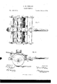
- A represents a rectangular frame of any suitable dimensions, provided with a crossgirt, B, in rear of the front bar of the frame. 0n the under sides of the side pieces of the frame are secured suitable boxes to, in which a revolving shaft or axle, b, has its bearings. On this axle are placed a number of wheels orrollers, O O, the center apertures 01 of which are made considerably larger than the axle b, as shown in Fig. 2, sothat the rollers will easily adjust themselves to any unevenness in the ground over which they pass.
- D represents a stone-box to increase the weight of the rollers. It is supported from the frame A by braces h h above the rollers.
- E is the drivers seat, arranged behind the stone-box to balance the machine and relieve the pressure on the horses necks.
- G is the tongue or pole, fastened in suitable loops in the center of the front bar and cross-girt of the frame.
- the holes d in the rollers may be made be"- eled from each side to the center. This roller may be used for rolling the ground between corn-rows by simply removing the middle roller and inserting a plank in place thereof. It is also applicable in drilling grain and danting.
Landscapes
- Engineering & Computer Science (AREA)
- Architecture (AREA)
- Civil Engineering (AREA)
- Structural Engineering (AREA)
- Soil Working Implements (AREA)
Description
J. A. KEELER.
Land-Roller.
Patented July 20,1875.
N. PEYERS, PHOTO-LITHOGRAPHER, WASHINGTON. D C.
ATENT JULIUS A. KEELER, OF OLATHE, KANSAS.
IMPROVEMENT IN LAND-ROLLERS.
Specification forming part of Letters Patent No. l65,@39, dated July 20, 1875; application filed June 9, 1875.
To all whom it may concern:
Be it known that I, JULIUS A. KEELER, of Olathe, in the county of Johnson and State of Kansas, have invented certain new and useful Improvements in Land-Rollers; and I do hereby declare that the following is a full, clear, and exact description thereof, reference being had to the accompanying drawings, and to the letters of reference marked thereon, which form part of this specification.
The nature of my invention consists in the construction and arrangement of a land or field roller, as will be hereinafter more fully set forth.
In order to enable others skilled in the art to which my invention appertains to make and use the same, I will now proceed to describe its construction and operation, referring to the annexed drawing, in Which Figure 1 is a plan view of my land or field roller; and Fig. 2 is a section of the same through the line at m, Fig. 1.
A represents a rectangular frame of any suitable dimensions, provided with a crossgirt, B, in rear of the front bar of the frame. 0n the under sides of the side pieces of the frame are secured suitable boxes to, in which a revolving shaft or axle, b, has its bearings. On this axle are placed a number of wheels orrollers, O O, the center apertures 01 of which are made considerably larger than the axle b, as shown in Fig. 2, sothat the rollers will easily adjust themselves to any unevenness in the ground over which they pass. D represents a stone-box to increase the weight of the rollers. It is supported from the frame A by braces h h above the rollers. E is the drivers seat, arranged behind the stone-box to balance the machine and relieve the pressure on the horses necks. G is the tongue or pole, fastened in suitable loops in the center of the front bar and cross-girt of the frame. By the rollers revolving on the axle and the axle revolving in its bearings the friction is entirely on the bearings.
The holes d in the rollers may be made be"- eled from each side to the center. This roller may be used for rolling the ground between corn-rows by simply removing the middle roller and inserting a plank in place thereof. It is also applicable in drilling grain and danting.
Having thus fully described my invention, what I claim as new, and desire to secure by Letters Patent, is-
In a land-roller, a series of wheels or rollers, 0, having enlarged central apertures d cl,
and revolving around a common axle, substantially as and for the purposes herein set forth.
In testimony that I claim the foregoing as my own I affix my signature in presence of two witnesses.
JULIUS A. KEELER.
Witnesses:
ELIAS RHOADES, Jr., WILL. D. LINTON.
Publications (1)
| Publication Number | Publication Date |
|---|---|
| US165839A true US165839A (en) | 1875-07-20 |
Family
ID=2235248
Family Applications (1)
| Application Number | Title | Priority Date | Filing Date |
|---|---|---|---|
| US165839D Expired - Lifetime US165839A (en) | Improvement in land-rollers |
Country Status (1)
| Country | Link |
|---|---|
| US (1) | US165839A (en) |
-
0
- US US165839D patent/US165839A/en not_active Expired - Lifetime
Similar Documents
| Publication | Publication Date | Title |
|---|---|---|
| US166597A (en) | Improvement in cotton-choppers | |
| US151174A (en) | Improvement in land-rollers | |
| US149117A (en) | Improvement in rotary harrows | |
| US335077A (en) | Iand-roller | |
| US799488A (en) | Combined stalk-cutter and roller. | |
| US265539A (en) | Land-roller | |
| US122251A (en) | Improvement in revolving harrows | |
| US319725A (en) | Land-roller | |
| US500253A (en) | Revolving harrow | |
| US218423A (en) | Improvement in adjustable roller and stalk-cutter | |
| US368926A (en) | Land-roller | |
| US214802A (en) | Improvement in land roller and pulverizer | |
| US644604A (en) | Combined harrow and roller. | |
| US460546A (en) | Allen | |
| US398937A (en) | Rotary harrow | |
| US137611A (en) | Improvement in wheel-plows | |
| US148450A (en) | Improvement in wheel-harrows | |
| US121157A (en) | Improvement in land-rollers | |
| US711417A (en) | Cotton-chopper. | |
| US337577A (en) | Land-roller | |
| US446306A (en) | Land-roller | |
| US273909A (en) | Land-roller | |
| US320067A (en) | Harrow | |
| US181978A (en) | Improvement in combined seed-planter and cultivator | |
| US506251A (en) | Combined planter and fertilizer-distributer |