US1636065A - High-pressure gas valve and shipping plug - Google Patents
High-pressure gas valve and shipping plug Download PDFInfo
- Publication number
- US1636065A US1636065A US529798A US52979822A US1636065A US 1636065 A US1636065 A US 1636065A US 529798 A US529798 A US 529798A US 52979822 A US52979822 A US 52979822A US 1636065 A US1636065 A US 1636065A
- Authority
- US
- United States
- Prior art keywords
- valve
- pressure
- passage
- escape
- container
- Prior art date
- Legal status (The legal status is an assumption and is not a legal conclusion. Google has not performed a legal analysis and makes no representation as to the accuracy of the status listed.)
- Expired - Lifetime
Links
Images
Classifications
-
- F—MECHANICAL ENGINEERING; LIGHTING; HEATING; WEAPONS; BLASTING
- F16—ENGINEERING ELEMENTS AND UNITS; GENERAL MEASURES FOR PRODUCING AND MAINTAINING EFFECTIVE FUNCTIONING OF MACHINES OR INSTALLATIONS; THERMAL INSULATION IN GENERAL
- F16K—VALVES; TAPS; COCKS; ACTUATING-FLOATS; DEVICES FOR VENTING OR AERATING
- F16K17/00—Safety valves; Equalising valves, e.g. pressure relief valves
- F16K17/36—Safety valves; Equalising valves, e.g. pressure relief valves actuated in consequence of extraneous circumstances, e.g. shock, change of position
- F16K17/38—Safety valves; Equalising valves, e.g. pressure relief valves actuated in consequence of extraneous circumstances, e.g. shock, change of position of excessive temperature
- F16K17/383—Safety valves; Equalising valves, e.g. pressure relief valves actuated in consequence of extraneous circumstances, e.g. shock, change of position of excessive temperature the valve comprising fusible, softening or meltable elements, e.g. used as link, blocking element, seal, closure plug
-
- Y—GENERAL TAGGING OF NEW TECHNOLOGICAL DEVELOPMENTS; GENERAL TAGGING OF CROSS-SECTIONAL TECHNOLOGIES SPANNING OVER SEVERAL SECTIONS OF THE IPC; TECHNICAL SUBJECTS COVERED BY FORMER USPC CROSS-REFERENCE ART COLLECTIONS [XRACs] AND DIGESTS
- Y10—TECHNICAL SUBJECTS COVERED BY FORMER USPC
- Y10T—TECHNICAL SUBJECTS COVERED BY FORMER US CLASSIFICATION
- Y10T137/00—Fluid handling
- Y10T137/1624—Destructible or deformable element controlled
- Y10T137/1797—Heat destructible or fusible
- Y10T137/1804—With second sensing means
-
- Y—GENERAL TAGGING OF NEW TECHNOLOGICAL DEVELOPMENTS; GENERAL TAGGING OF CROSS-SECTIONAL TECHNOLOGIES SPANNING OVER SEVERAL SECTIONS OF THE IPC; TECHNICAL SUBJECTS COVERED BY FORMER USPC CROSS-REFERENCE ART COLLECTIONS [XRACs] AND DIGESTS
- Y10—TECHNICAL SUBJECTS COVERED BY FORMER USPC
- Y10T—TECHNICAL SUBJECTS COVERED BY FORMER US CLASSIFICATION
- Y10T137/00—Fluid handling
- Y10T137/1624—Destructible or deformable element controlled
- Y10T137/1797—Heat destructible or fusible
- Y10T137/1812—In fluid flow path
Definitions
- the present invention relates to pressure
- wie retaining and controlling devices are adapted to accomplish all ci? these results, and comprise a sealing folug for use when the cylinders are in storor in transit, which will eiectively ren the contents oi'f the cylinder and which 'will respond to temperatures which would be dangerous by permitting escape of the caract proportion the contents of the cylinder which is necessary to the maintenance ci a normal or safe pressure, immediately closing 'when the pressure is reduced to normal; and a controlling and release valve for use in delivering the gas Jfrom the container, which control release valve is also pro- *vided with a sciety device so as to guard against ences cve expansion due to an unuson rise in iperatu're or other causes.4
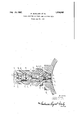
- Thedrawing is a vertical sectional view of a shipping plug, a portion' of any suitable cylinder or retainer being conventionally shown.
- the plug member 11 is threaded into the neck of thev container with preferably a tapered gas tight joint.
- the member 11 has a through passage, the lower end 12 of which is enlarged and has a valve seat 13 formed at its top.
- a ⁇ valve member 14 seats against this valve seat 13 and is normally held by the spring 15 in closed position, that spring being supported by an annular plug 16 threaded into the lower end of the chamber 12, the plug 16 being nicked or otherwise fashioned to receive a suitable tool for inserting or removing it from the chamber 12.
- the stem 17 of the valve passes upwardly through the passage in the member 11 projecting slightly above the bottom of the recess 18 in the plug member 11.
- the said stem 17 has a through assage 19, the lower end of which is closed y a seal 20 of. material which will -fuse at a predetermined n the passage 19 in the valve and permlt escape oi' excess pressure due to increased temperature.
- the member 21 has the passage 22, the lower end of whichis enlarged, as shown, so 'that when the -member 21 is inserted ir the recess i8, the enlarged lower end oit the passage 22 will span the upper end of the stem 17 of the valve, and all danger of unseating that valve is eliminated.
- the passage 22 has formed, at its upper end, a valve seat 23 against which is the down- ⁇ wardly seating valve 24 having wing projections 25 which guide its movements in the valve receiving chamber, the valve 24 being held normally closed by a sprin an annular washer 27 being inter ose be tween the spring and the valve, t e upper end of the spring bearing a ainst an annular washer 28, which was er is suitably packed in its seat and is held tightl thereto by the screw plug 29 threaded in t e upper end of the member 21 and provided with the vertical passage 30 and lateralpassages 31.
- the assage 30 in the screw plug is sealed. at its lower end, by a disk of material 32 which will fuse at a predetermined temperature.
- V and the'container 10 will, as is usual, be
- a temporary protecting cap (not shown) to guard the shipping plug against injury in transportation.
- a pressure storage container a part having a passage therethrough, a valve in said passage seated by the pressure within the container, means associated with said valve to relieve pressure past said valve under emergency conditions, a second valve controlling the flow past said first named valve, and means normally closing said second valve against pressure.
- a part having a passage therethrough, a pressure seated valve in said passage having an escape aperture, destructible means normall closing said aperture, a second valve contro ling How from said aperture, means for closing said second valve, an emergency escape passage leading to atmosphere, and fusible means normally closing said escape assage.
- a plug member adapted to engage an aperture in a ⁇ container and having a passage there'- through, a pressure closed apertured valve in said passage, fusible means closing the aperture in said valve, a second member. detachably connected to ,said first named member and having a through passage, a valve closing against pressure mounted in said passage, a spring closing said valve against normal pressure, a screw plug in said second member having an emergenc escape passage therethrough, and fusib e means normally closing said passage.
Description
HIGH PRESSURE GAS VALVE AND SHIPPING PLUG Filed Jan. l5, 1922 6g! LX1-56%! Patented July 19, '1927.
UNITED STATES PATENT OFFICE.
l PHILIP MUELLER, F DECATUR, ILLINOIS, `AND CHARLES A. HILL, F PORT HUBON,
MICHIGAN, ASSIGNOBS T0 ADOLPH `MUELLEB, TRUSTEE, 0F DECATUB, ILLINOIS.
HIGH-PRESSURE GAS VALVE ANDSHIPPING PLUG.
lApplication Med January 16, 1922. Serial No. 529,798.
The present invention relates to pressure,
controlling and retaining devices for fluid containers, andv in the particular embodiment herein shown and described, will be disclosed in connection with gas containers,
but it will he understood that it may be used with any fluid container in which pressure must be retained or controlled.
-Primarily. the development is intended for Vuse with the cylinders `in which rare @will iii or lethal gases are stored.y In the storage of gases of this character, it is essential that their escape be very carefully guarded against, as the loss of the rare gas by leakage is costly, and the escape of lethal gas is, of course, dangerous. The containers or cylinders in which these gases are ordinarily stored are subjected to various conditions 1n transportation and in storage warehouses, and it is necessary to provide sealing means l'or such containers which will meet any extraordinary conditions, as, for example, high temperatures which would cause expansion of the gases beyond the safetvpoint, and
explosion ci2 the containers. Furthermore,
means must be provided for the filling or drawing oii oli the gases from the container, and such means must. of course. be capable oi eec'tively controlling the iiow to and irom the containers to the receptacles which receive the gas, and must be so made as that all danger ci escape, except through the desired conduit. will be eliminated.
wie retaining and controlling devices, herein disclosed, are adapted to accomplish all ci? these results, and comprise a sealing folug for use when the cylinders are in storor in transit, which will eiectively ren the contents oi'f the cylinder and which 'will respond to temperatures which would be dangerous by permitting escape of the caract proportion the contents of the cylinder which is necessary to the maintenance ci a normal or safe pressure, immediately closing 'when the pressure is reduced to normal; and a controlling and release valve for use in delivering the gas Jfrom the container, which control release valve is also pro- *vided with a sciety device so as to guard against ences cve expansion due to an unuson rise in iperatu're or other causes.4
loe deyelopmcnt tahzes several forms, as
`temperature so as to o will appear from the drawing and description, andv in said drawing:
Thedrawing is a vertical sectional view of a shipping plug, a portion' of any suitable cylinder or retainer being conventionally shown.
Referring tothe drawings by numbers, like numbers indicating like parts in the several views, indicates any suitable container having a threaded neck portion to receive a shipping plug or valve.
In the form of the development shown in the drawing the plug member 11 is threaded into the neck of thev container with preferably a tapered gas tight joint. The member 11 has a through passage, the lower end 12 of which is enlarged and has a valve seat 13 formed at its top. A` valve member 14 seats against this valve seat 13 and is normally held by the spring 15 in closed position, that spring being supported by an annular plug 16 threaded into the lower end of the chamber 12, the plug 16 being nicked or otherwise fashioned to receive a suitable tool for inserting or removing it from the chamber 12. The stem 17 of the valve passes upwardly through the passage in the member 11 projecting slightly above the bottom of the recess 18 in the plug member 11. The said stem 17 has a through assage 19, the lower end of which is closed y a seal 20 of. material which will -fuse at a predetermined n the passage 19 in the valve and permlt escape oi' excess pressure due to increased temperature.
.Itis obvious that if no provision was made for controlling the escape oi gas after the s'eal 2O has melted, the entire contents oi" the container 10 will escape, and this, in the case of rare gases, would be costly', and in' 18 in. the top ofthe plug member l1.
The member 21 has the passage 22, the lower end of whichis enlarged, as shown, so 'that when the -member 21 is inserted ir the recess i8, the enlarged lower end oit the passage 22 will span the upper end of the stem 17 of the valve, and all danger of unseating that valve is eliminated. The passage 22 has formed, at its upper end, a valve seat 23 against which is the down-` wardly seating valve 24 having wing projections 25 which guide its movements in the valve receiving chamber, the valve 24 being held normally closed by a sprin an annular washer 27 being inter ose be tween the spring and the valve, t e upper end of the spring bearing a ainst an annular washer 28, which was er is suitably packed in its seat and is held tightl thereto by the screw plug 29 threaded in t e upper end of the member 21 and provided with the vertical passage 30 and lateralpassages 31. The assage 30 in the screw plug is sealed. at its lower end, by a disk of material 32 which will fuse at a predetermined temperature. l
From the foregoing, it will be seen that, under normal conditions, escape of the contentsof the chamber '10 is prevented by theI two valves 14 and 24, the valve 14 being held tightly to' its seat by pressure within the container, and the valve 24 being held tivhtl to its seat by the spring 26, which is o suthcient strength to maintain that valve 24 closed against the normal ressure in the container 10. If, therefore, or any reason, the valve `14 should become deranged, the gas wouldl still be efectivel held by the second valve 24, and a dou le element of safety is, therefore, provided.
It will be seen, however, that in event of excess pressure developing in the container because of high temperature, the sealing disks 20 and 32, responding to that same high temperature, will melt, and there will then be a through passage from the container 10 to the escape passages 31 in the screw plug 29; the valve 24, of course, respending to the excess pressure in the cylinder. will be opened against the spring 26 aud ermit the dangerous pressure to esca It will be observed, however, that the va ve 24 and its spring 26 will, the instant pressure has been reduced to normal, close and effectively prevent the loss of the entire contents of the container. This is of great im-. portance, for, after the reduction of a comparatively few pounds in the container, the point of danger of explosion has been passed, and the contents remaining in the cylinder can thus be retained.
This constitutes the shipping plug :for fluid containers. It will be understood that the plug members 11 and 21'A are hexed, or
. otherwise suitably formed, for the application of proper tools for inserting or removing them from their assembled condition, V and the'container 10 will, as is usual, be
provided with an exteriorly threaded neckA to receive a temporary protecting cap (not shown) to guard the shipping plug against injury in transportation.
It is to be understood, that instead of the fusible seals 20 and 32, we may, if desired,` use seals made ot' frangible material, which will break when the pressure reaches a danger point. f
Changes in the construction and assemblage of parts as constitute mechanical skill and the adoption of equivalent 'expedients may, of course,'be made to this disclosure, and still he within the purview of the invention.
We claim:
1. In a pressure storage container, a part having a passage therethrough, a valve in said passage seated by the pressure within the container, means associated with said valve to relieve pressure past said valve under emergency conditions, a second valve controlling the flow past said first named valve, and means normally closing said second valve against pressure.
2. In a device of the class described, a part having a passage theretrough, a pressure seated valve in said passage, means associated with said valve to relieve pressure past said valve under emergency conditions, a second valve controlling the flow past said first named valve, means normally closin said second valve against pressure, an means associated with said secondvalve to relieve pressure to atmosphere under emergency conditions.
3. In a device of the class described, a part having a passage therethrough, a pressure seated `valve in said passage, destructible means normally preventing flow past said valve, a second valve controlling the flow past said first named valve, means normally closing said second valve, and means destructible under emergency conditions normally preventing ow past said second valve.
4. In a device of the class described, a part having a passage therethrough, a pressure seated valve in said passage having an escape aperture, destructible means normall closing said aperture, a second valve contro ling How from said aperture, means for closing said second valve, an emergency escape passage leading to atmosphere, and fusible means normally closing said escape assage.
5. In a device of the class descri ed, the combination of a part having a passage, a pressure seated valve in said passage having an escape aperture, fusible means normally closing said aperture, a second lvalve in said passage opening under-pressure, and means for seating said second valve against normal pressure. f
6. In a device of the class described, the
pressure seated valve in said means normally ,combination of a part having avpassage, a Y
closing said aperture, a `second Avalve in said passage opening under ressure, means for seating said second va ve against normal ressure, .an emergenc escape passagelead- 5 lng to atmosphere, an fusible means closing sald escape passage.
7. In a device of the class described, the
Ycombination `of a part having ar passage therethrough, a pressure closed valve in said 10 passage having an escape aperture, fusibleY means closing said aperture, a pressure opened valve in said passage, a spring closing said valve against normal pressure, an emergenc escape opening to atmosphere be- 15 hind sai second valve, and fusible means closing said second emergency escape pas- Sage combination of a memberadapted to' be inl serted in an aperture in a container and having a passage therethrough, a valve normally closed by the container pressure in said assage and having an escape aperture, fusile means closing said aperture, a second member detachably connected with said first 8..In a device of the class described, the' mal pressure, an emergency esca ptag to atmospherein said second mem said valve, and fusible means closing said second escape passage. y A
` 9. In a device of the class decribed, a plug member adapted to engage an aperture in a `container and having a passage there'- through, a pressure closed apertured valve in said passage, fusible means closing the aperture in said valve, a second member. detachably connected to ,said first named member and having a through passage, a valve closing against pressure mounted in said passage, a spring closing said valve against normal pressure, a screw plug in said second member having an emergenc escape passage therethrough, and fusib e means normally closing said passage.
In testimony whereof We have hereunto set our hands.
PHILIP MUELLER. CHARLES lA. HILL.
Priority Applications (1)
| Application Number | Priority Date | Filing Date | Title |
|---|---|---|---|
| US529798A US1636065A (en) | 1922-01-16 | 1922-01-16 | High-pressure gas valve and shipping plug |
Applications Claiming Priority (1)
| Application Number | Priority Date | Filing Date | Title |
|---|---|---|---|
| US529798A US1636065A (en) | 1922-01-16 | 1922-01-16 | High-pressure gas valve and shipping plug |
Publications (1)
| Publication Number | Publication Date |
|---|---|
| US1636065A true US1636065A (en) | 1927-07-19 |
Family
ID=24111272
Family Applications (1)
| Application Number | Title | Priority Date | Filing Date |
|---|---|---|---|
| US529798A Expired - Lifetime US1636065A (en) | 1922-01-16 | 1922-01-16 | High-pressure gas valve and shipping plug |
Country Status (1)
| Country | Link |
|---|---|
| US (1) | US1636065A (en) |
Cited By (6)
| Publication number | Priority date | Publication date | Assignee | Title |
|---|---|---|---|---|
| US3384101A (en) * | 1965-01-27 | 1968-05-21 | Julius F. Melzer | Safety valve |
| US5632297A (en) * | 1995-09-26 | 1997-05-27 | Amcast Industrial Corporation | Piston-type thermally or pressure activated relief device |
| US20030221720A1 (en) * | 2002-04-23 | 2003-12-04 | Erick Girouard | Pressure relief device |
| US6814097B2 (en) | 2001-03-20 | 2004-11-09 | Teleflex Gfi Control Systems L.P. | Pressure relief device |
| GB2446483A (en) * | 2006-12-13 | 2008-08-13 | Yi-Jhih Bai | Safety device |
| US20190120394A1 (en) * | 2016-03-28 | 2019-04-25 | Ojc Co., Ltd. | Safety valve and gas cylinder having same |
-
1922
- 1922-01-16 US US529798A patent/US1636065A/en not_active Expired - Lifetime
Cited By (9)
| Publication number | Priority date | Publication date | Assignee | Title |
|---|---|---|---|---|
| US3384101A (en) * | 1965-01-27 | 1968-05-21 | Julius F. Melzer | Safety valve |
| US5632297A (en) * | 1995-09-26 | 1997-05-27 | Amcast Industrial Corporation | Piston-type thermally or pressure activated relief device |
| US6814097B2 (en) | 2001-03-20 | 2004-11-09 | Teleflex Gfi Control Systems L.P. | Pressure relief device |
| US20030221720A1 (en) * | 2002-04-23 | 2003-12-04 | Erick Girouard | Pressure relief device |
| US6851445B2 (en) | 2002-04-23 | 2005-02-08 | Teleflex Gfi Control Systems L.P. | Pressure relief device |
| GB2446483A (en) * | 2006-12-13 | 2008-08-13 | Yi-Jhih Bai | Safety device |
| GB2446483B (en) * | 2006-12-13 | 2011-11-23 | Yi-Jhih Bai | Safety flow guide protection device |
| US20190120394A1 (en) * | 2016-03-28 | 2019-04-25 | Ojc Co., Ltd. | Safety valve and gas cylinder having same |
| US10683947B2 (en) * | 2016-03-28 | 2020-06-16 | Ojc Co., Ltd. | Safety valve and gas cylinder having same |
Similar Documents
| Publication | Publication Date | Title |
|---|---|---|
| US4077422A (en) | Flow control means for compressed gas cylinders | |
| US3122162A (en) | Flow control device | |
| US9995407B2 (en) | Integrated safety device for self-propulsion gas systems | |
| US2239169A (en) | Safety valve | |
| US4273151A (en) | In-line relief valve | |
| US11953155B2 (en) | Device for storing compressed gas, vehicle | |
| US1636065A (en) | High-pressure gas valve and shipping plug | |
| US9915372B2 (en) | High integrity pressure protecting system (HIPPS) for a fluid line | |
| US4388940A (en) | Pressure relief device | |
| US4172468A (en) | Pressure shock absorber for oxygen-regulator supply system | |
| US3709255A (en) | High pressure valves | |
| US5261450A (en) | Pressure relief vent with surge suppression | |
| US2696083A (en) | Fluid flow control system | |
| US2638924A (en) | Automatic tank valve | |
| US2363521A (en) | Valve device | |
| US1606831A (en) | Plug for gas containers | |
| US2385489A (en) | Valve assembly | |
| US2346223A (en) | Self-closing valve for single directional fluid flow | |
| US869878A (en) | Safety cut-off for storage lighting systems. | |
| US1162153A (en) | Safety-valve. | |
| US3955589A (en) | Fluid isolating valve | |
| JPH04502801A (en) | Fire shutoff device | |
| US2740418A (en) | Combined excess flow and shut off valve | |
| US2589346A (en) | Emergency valve | |
| US3605948A (en) | Lubricant fitting for valves |