US1620723A - Loom for weaving - Google Patents
Loom for weaving Download PDFInfo
- Publication number
- US1620723A US1620723A US9510A US951025A US1620723A US 1620723 A US1620723 A US 1620723A US 9510 A US9510 A US 9510A US 951025 A US951025 A US 951025A US 1620723 A US1620723 A US 1620723A
- Authority
- US
- United States
- Prior art keywords
- weft
- loom
- weaving
- feeder
- shed
- Prior art date
- Legal status (The legal status is an assumption and is not a legal conclusion. Google has not performed a legal analysis and makes no representation as to the accuracy of the status listed.)
- Expired - Lifetime
Links
Images

Classifications
-
- D—TEXTILES; PAPER
- D03—WEAVING
- D03D—WOVEN FABRICS; METHODS OF WEAVING; LOOMS
- D03D47/00—Looms in which bulk supply of weft does not pass through shed, e.g. shuttleless looms, gripper shuttle looms, dummy shuttle looms
Definitions
- This invention relates to improvements in weft inserting mechanism for looms for weaving of the type in which the weft is inserted half way through the shed by means of a weft rod or needle and taken the remainder of the distance by means of a hook device.
- a combined weft insertion and withdrawing rod is arranged at both sides of the loom so that a weft thread can be inserted double from either side of the shed to the centre and withdrawn from the other side after the portion attached to the end of the previous pick has been cut.
- the insertion devices consist of a combined fork and hook, so that according to the work desired each weft insertion device may serve as weft feeder or remover.
- each weft insertion device may serve as weft feeder or remover.
- the latter is provided with protecting contrivances which divide the warp threads.
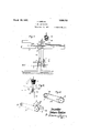
- FIG. 1 shows the front view of the right side of a loom with the weft inserting device for one feeder and bobbin;
- Fig. 2 shows the side of the slay, partly in section, from which can be seen the working operation of the thread feeder;
- Fig. 3 is a modification of the arrangement shown in Fig. 2 showing a pattern chain for operating the thread feeder.
- Fig. 4 shows a front view of the upper part'of the weft feeder with the front parts, in the shape of fork and hook, of the weft insertion device.
- Fig. 5 is a section through the insertion device.
- Fig. 6 is a plan view of the upper part of
- Fig. 8 is a side view of part of Fig. 7;
- Fig. 9 is a plan similar to Fig. 7 showing the hooks 23 in the centre of the shed and with the protecting device or warp divider 25 in section.
- the loom operates as follows
- the rotating shaft 1 drives, through the chain 4; and chain wheels 2 and 3, the shaft 5 on which latter a pattern disc 6 is fixed.
- the disc 6 by means of the lever 7, runner 8. and the bracket 9 lifts at the moment of the impact of the reedthe thread feeder 10, which is bent at right angles at the top 11 and is connected to slay 12 at 13, so that the warp feeder will take the position shown in dotted lines in Fig. 6.
- the weft 15 extends from the bobbin at a particular side of the loom through the eyes 16, 17 direct to the fell of the cloth as shown at 20, Fig. i in which position it does not lie in the path of the inserter 22.
- the feeder 11 When it is desired to insert a weft however, from this particular side the feeder 11 is raised at the beat up so as to pass over the weft 20 when the slay moves back from the dotted line position Fig. 6, to that shown in full lines. The feeder is then moved down taking with it the weft 2O into the position 20, 20 where it lies in the path of the inserter 22. Accordingly therefore as the feeder 11 at a. particular side is, or is not operated, a weft is or is not inserted from this side when the inserting device 22 moves inwards.
- a protector 24 In order to prevent any loose Warp'threads, Which may be hanging down, from being damaged by the insertion device t-he latter isprovidedwith a protector 24, ending in point 25 by which "the Warp threads are divided.
Description
1 19 March 5, 27 J. GABLER LOOM FOR WEAVING Filed Feb. 16, 1925 2 Sheets-Sheet 1 Jnvenlnr Juhann E'abler:
1 March 927 J. GABLER LOOM FOR WEAVING 2 Sheets-Sheet 2 Filed Feb. 16. 1925 a v V Z? Johann Eabler:
Patented Mar. 15, 1927.
UNETE STATES rezam PATENT "QFFICE.
JOI-IA'NN GABLER, 0F ETTLINGEN, GERMANY.
LOOM non WEAVING.
Application filed February 18, 1925, Serial No. 9,510, and in Germany February 13, 1924.
This invention relates to improvements in weft inserting mechanism for looms for weaving of the type in which the weft is inserted half way through the shed by means of a weft rod or needle and taken the remainder of the distance by means of a hook device. 1
According to this invention a combined weft insertion and withdrawing rod is arranged at both sides of the loom so that a weft thread can be inserted double from either side of the shed to the centre and withdrawn from the other side after the portion attached to the end of the previous pick has been cut.
Owing to the fact that the weft is inserted in a given rotation as desired from both sides of the weave, a firm edge and a regularly bound selvedge of fabric can be made for any combination. For instance, when using a simple linen'binding it is advisable to insert the weft in the proportion of 2:2, i. e. from each side two wefts one after the other are inserted, with the result that each weft inserted from the same side will lie in a different shed and engages the most extreme warps.
Through this invention it is further possible to weave in multi-colors a number of patterns by using two bobbins with differently dyed weft material, inasmuch as according to the pattern as many wefts are inserted from one side as correspond to the requirements.
In order to enable the feeders to carry out their task in a regular manner, the insertion devices consist of a combined fork and hook, so that according to the work desired each weft insertion device may serve as weft feeder or remover. In order to prevent any loose warp threads from being caught on the entry of the new insertion device in the shape of a fork and hook, the latter is provided with protecting contrivances which divide the warp threads.
One form of the invention is illustrated in the accompanying drawing viz Fig. 1 shows the front view of the right side of a loom with the weft inserting device for one feeder and bobbin;
Fig. 2 shows the side of the slay, partly in section, from which can be seen the working operation of the thread feeder;
Fig. 3 is a modification of the arrangement shown in Fig. 2 showing a pattern chain for operating the thread feeder.
Fig. 4 shows a front view of the upper part'of the weft feeder with the front parts, in the shape of fork and hook, of the weft insertion device.
Fig. 5 is a section through the insertion device.
Fig. 6 is a plan view of the upper part of,
from below of part of Fig. 4.
Fig. 8 is a side view of part of Fig. 7; and
Fig. 9 is a plan similar to Fig. 7 showing the hooks 23 in the centre of the shed and with the protecting device or warp divider 25 in section.
The loom operates as follows The rotating shaft 1 drives, through the chain 4; and chain wheels 2 and 3, the shaft 5 on which latter a pattern disc 6 is fixed. The disc 6 by means of the lever 7, runner 8. and the bracket 9 lifts at the moment of the impact of the reedthe thread feeder 10, which is bent at right angles at the top 11 and is connected to slay 12 at 13, so that the warp feeder will take the position shown in dotted lines in Fig. 6. Normally the weft 15 extends from the bobbin at a particular side of the loom through the eyes 16, 17 direct to the fell of the cloth as shown at 20, Fig. i in which position it does not lie in the path of the inserter 22.
When it is desired to insert a weft however, from this particular side the feeder 11 is raised at the beat up so as to pass over the weft 20 when the slay moves back from the dotted line position Fig. 6, to that shown in full lines. The feeder is then moved down taking with it the weft 2O into the position 20, 20 where it lies in the path of the inserter 22. Accordingly therefore as the feeder 11 at a. particular side is, or is not operated, a weft is or is not inserted from this side when the inserting device 22 moves inwards.
When the insertion device 22, acting in part 20 of the weft thread 20 lies in i 20 along with it in the Well-knownmanner as described in my prior British specification No. 204,143.
In order to prevent any loose Warp'threads, Which may be hanging down, from being damaged by the insertion device t-he latter isprovidedwith a protector 24, ending in point 25 by which "the Warp threads are divided.
In orderto have the feeders Workingin the desired rotation, 'the' pattern disc or dobby, which Works the feeders, is provided WVltlLSeVeIELl studs, 26 and 27. Itais of course necessary that the shaft 5 stand in the correct rat1o'ofgear to the inserting devices. In order to give a greater range of patterns, a pattern chain with studsor ta-ppets 28 may be used, as shown in Fig. 3.
It is of course necessary thatthesame arrangement should exist onboth sides of the machine.
What I claim as my invention and desire to protect by Letters Patent is 1. lVeft inserting mechanism for looms for Weaving of the type referred to comprising 'at both sides ofthefloom a combined Weft insertion and Withdrawing rod; a sliding rod to bring the'weft into the path of the in serter and a pattern chain for controlling -the movement of the sliding rod.
' 2.;VVeft .=inserting= mechanism for looms for Weaving of the type referred to compris- -ing at both sides of the loom a forked ended rod for inserting a Weft thread to the centre of the shed, a hook'thereon for With- :drawinga ,WQft thread inserted to the cen tre of the shed from the opposite side of the loom, a sliding rod'to bring the Weft into the'path of the inserter and a pattern chain for controlling the movement of'the the movement ofthe sliding rod.
In testimony whereof I have hereunto set my hand.
JOHANN GABLER.
Applications Claiming Priority (1)
| Application Number | Priority Date | Filing Date | Title |
|---|---|---|---|
| DE1620723X | 1924-02-13 |
Publications (1)
| Publication Number | Publication Date |
|---|---|
| US1620723A true US1620723A (en) | 1927-03-15 |
Family
ID=7737393
Family Applications (1)
| Application Number | Title | Priority Date | Filing Date |
|---|---|---|---|
| US9510A Expired - Lifetime US1620723A (en) | 1924-02-13 | 1925-02-16 | Loom for weaving |
Country Status (1)
| Country | Link |
|---|---|
| US (1) | US1620723A (en) |
Cited By (2)
| Publication number | Priority date | Publication date | Assignee | Title |
|---|---|---|---|---|
| US3347284A (en) * | 1965-05-22 | 1967-10-17 | Dornier Gmbh Lindauer | Weft thread inserting device for shuttleless looms |
| US3916956A (en) * | 1974-12-10 | 1975-11-04 | Joan Fabrics Corp | Needle loom for weaving plush fabric |
-
1925
- 1925-02-16 US US9510A patent/US1620723A/en not_active Expired - Lifetime
Cited By (2)
| Publication number | Priority date | Publication date | Assignee | Title |
|---|---|---|---|---|
| US3347284A (en) * | 1965-05-22 | 1967-10-17 | Dornier Gmbh Lindauer | Weft thread inserting device for shuttleless looms |
| US3916956A (en) * | 1974-12-10 | 1975-11-04 | Joan Fabrics Corp | Needle loom for weaving plush fabric |
Similar Documents
| Publication | Publication Date | Title |
|---|---|---|
| IE40813L (en) | Selvedge formation during weaving | |
| US2918945A (en) | Selvage and method and means for making same | |
| US1620723A (en) | Loom for weaving | |
| US3910317A (en) | Weaving machine for terry cloth | |
| US2152255A (en) | Method and loom for weaving | |
| US2602472A (en) | Method and means for changing the clamping force at which and during each time a weft thread end is temporarily held during weaving on looms | |
| GB214198A (en) | A new selvedge for woven material having separate wefts formed of measured lengths of thread and means for producing same | |
| US1676039A (en) | Pile-fabric loom | |
| US2714397A (en) | Device for shifting pile warp crossings toward fell | |
| US3241576A (en) | Weft guide means for shuttleless looms | |
| US1919147A (en) | Needle loom | |
| US1715985A (en) | Thread cutter for box looms | |
| US1944121A (en) | Tuft pile fabric loom | |
| US1874555A (en) | Loose reed stopping mechanism for looms | |
| US2541745A (en) | Method of and apparatus for weaving leno fabric | |
| US1998306A (en) | Movable reed mechanism | |
| US502024A (en) | woodward | |
| US3079955A (en) | Terry selvage filling holder and method | |
| US2467871A (en) | Stop motion for weft replenishing looms | |
| US2226267A (en) | Thread positioner for weft replenishing looms | |
| US1872979A (en) | Selvage trimmer for box looms | |
| US1363492A (en) | Stop mechanism for looms | |
| US1834357A (en) | Method for controlling weft ends in weft replenishing looms | |
| US2596315A (en) | Loom box front | |
| US2355531A (en) | Loom for weaving ladder tapes |