US1591069A - Tube-cut-off machine - Google Patents
Tube-cut-off machine Download PDFInfo
- Publication number
- US1591069A US1591069A US658235A US65823523A US1591069A US 1591069 A US1591069 A US 1591069A US 658235 A US658235 A US 658235A US 65823523 A US65823523 A US 65823523A US 1591069 A US1591069 A US 1591069A
- Authority
- US
- United States
- Prior art keywords
- tube
- cutter
- shaft
- cam
- clutch
- Prior art date
- Legal status (The legal status is an assumption and is not a legal conclusion. Google has not performed a legal analysis and makes no representation as to the accuracy of the status listed.)
- Expired - Lifetime
Links
Images


Classifications
-
- B—PERFORMING OPERATIONS; TRANSPORTING
- B23—MACHINE TOOLS; METAL-WORKING NOT OTHERWISE PROVIDED FOR
- B23D—PLANING; SLOTTING; SHEARING; BROACHING; SAWING; FILING; SCRAPING; LIKE OPERATIONS FOR WORKING METAL BY REMOVING MATERIAL, NOT OTHERWISE PROVIDED FOR
- B23D21/00—Machines or devices for shearing or cutting tubes
-
- Y—GENERAL TAGGING OF NEW TECHNOLOGICAL DEVELOPMENTS; GENERAL TAGGING OF CROSS-SECTIONAL TECHNOLOGIES SPANNING OVER SEVERAL SECTIONS OF THE IPC; TECHNICAL SUBJECTS COVERED BY FORMER USPC CROSS-REFERENCE ART COLLECTIONS [XRACs] AND DIGESTS
- Y10—TECHNICAL SUBJECTS COVERED BY FORMER USPC
- Y10T—TECHNICAL SUBJECTS COVERED BY FORMER US CLASSIFICATION
- Y10T83/00—Cutting
- Y10T83/465—Cutting motion of tool has component in direction of moving work
- Y10T83/4653—With means to initiate intermittent tool action
- Y10T83/4656—Tool moved in response to work-sensing means
- Y10T83/4676—With work-responsive means to initiate flying movement of tool
-
- Y—GENERAL TAGGING OF NEW TECHNOLOGICAL DEVELOPMENTS; GENERAL TAGGING OF CROSS-SECTIONAL TECHNOLOGIES SPANNING OVER SEVERAL SECTIONS OF THE IPC; TECHNICAL SUBJECTS COVERED BY FORMER USPC CROSS-REFERENCE ART COLLECTIONS [XRACs] AND DIGESTS
- Y10—TECHNICAL SUBJECTS COVERED BY FORMER USPC
- Y10T—TECHNICAL SUBJECTS COVERED BY FORMER US CLASSIFICATION
- Y10T83/00—Cutting
- Y10T83/465—Cutting motion of tool has component in direction of moving work
- Y10T83/4757—Tool carrier shuttles rectilinearly parallel to direction of work feed
- Y10T83/4763—Both members of cutting pair on same carrier
-
- Y—GENERAL TAGGING OF NEW TECHNOLOGICAL DEVELOPMENTS; GENERAL TAGGING OF CROSS-SECTIONAL TECHNOLOGIES SPANNING OVER SEVERAL SECTIONS OF THE IPC; TECHNICAL SUBJECTS COVERED BY FORMER USPC CROSS-REFERENCE ART COLLECTIONS [XRACs] AND DIGESTS
- Y10—TECHNICAL SUBJECTS COVERED BY FORMER USPC
- Y10T—TECHNICAL SUBJECTS COVERED BY FORMER US CLASSIFICATION
- Y10T83/00—Cutting
- Y10T83/465—Cutting motion of tool has component in direction of moving work
- Y10T83/4766—Orbital motion of cutting blade
- Y10T83/4795—Rotary tool
- Y10T83/4812—Compound movement of tool during tool cycle
-
- Y—GENERAL TAGGING OF NEW TECHNOLOGICAL DEVELOPMENTS; GENERAL TAGGING OF CROSS-SECTIONAL TECHNOLOGIES SPANNING OVER SEVERAL SECTIONS OF THE IPC; TECHNICAL SUBJECTS COVERED BY FORMER USPC CROSS-REFERENCE ART COLLECTIONS [XRACs] AND DIGESTS
- Y10—TECHNICAL SUBJECTS COVERED BY FORMER USPC
- Y10T—TECHNICAL SUBJECTS COVERED BY FORMER US CLASSIFICATION
- Y10T83/00—Cutting
- Y10T83/465—Cutting motion of tool has component in direction of moving work
- Y10T83/4766—Orbital motion of cutting blade
- Y10T83/4795—Rotary tool
- Y10T83/4847—With cooperating stationary tool
Definitions
- My invention provides a highly efiicient t tube' cut-ofl machine adapted for very general use but particularly designed and espeially adapted for use to cut off thin brass.
- My invention provides a simple and highly efiicient tube-cutting nor shearing device
- the improved tube cut-off machine involves various novel'and important features, notably among which are simple and eflicient rice to travel with the moving tube while performing the cutting action and without interfering with the continuous operation of forming and feeding the tube; anda-simple and highly eflicient driving I clutch and clutch-tripping or actuating device controlled by movements of the formed tube and operating to automatically time the cutting of the tubefor predetermined lengths.
- Fig. 1 is a' plan view illustrating my in 4 vention applied to the deliveryiend of a tubeforming machine
- Fig. 2 is a side elevation of the parts shown in Fig.- 1;
- Fig. 3 is a horizontal I section taken approxlmately on the line 3--3 of Fig. 2;.
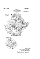
- Fig. 4 is a transverse vertical section taken a approximately on' the line 44 of Fig. 3;
- F g. 5 is a transverse vertical section taken approximately on the line 5-5 of Fig. 1, some parts-being. broken away; and
- Fig. 6 is a detail in transverse vertical section taken on the line of- Fig., 3'. t
- the tube-forming machine, the delivery end portion only of which is illustrated, may
- intermeshing gears 12 that connect the two shafts '10 and 11 for simulta'neous rotation and for rotation in synchronism with certain [other tube-feeding and forming'rollers, not Ishown. a a
- the laterally spaced plates 16 have bearing sleeves 18 through whichthe The formed tube A, as it leaves the forrn ing machine, passes through a 'guideblock 19, shown as supported from the frame 7 by a suitable clamping bracket 20. 'From the guide 19, the tube A passes-through a closeso which is rigidly secured a stationary tie- 1y fitting triangular in a projecting portion 16 of the inner earshown,
- riage plate 16 passes through closely fittitng triangular guide passages formed inrelatively fixed hardened shearing plates 21.
- the space between the shearing plates 21 is only wide enough to permit the movable cutterblade to pass therebetween with very slight clearance ⁇ f
- Rotatively mounted inthe plates 16 of the traveling cutter carrier and extending parallel to the guiderods 13, is a cutter shaft 24.
- This cutter shaft 24- isheld against endwise movements in respect to the cutter carriage or, otherwise stated, is causedto' travel with saidcutter carriage and, hence, to move axially'in respect to the main frame 7.
- a cylindrical cam 25 Keyed'or otherwise rigidly secured to the inner end of the cutter shaft 24 is a cylindrical cam 25. having a peripheral cam groove 26 in which works aroller-equipped stub 27 that is supported in a stationary position by 'a bracket 28, which, in turn, is rigidly secured to and projects. outward from the delivery end of the main frame 7.
- the nature of the cam groove 26 will be hereinafter stated.
- This shaft 29 is preferably ofronsiderably less diameter'th-an the shaft 24, is mounted to rotate inand slide through a bearing 30 on, the outer end tie-plate 14, and its inner end' is telescoped into the outer end of the shaft 24 and is connected for rotation therewith by a long key and groove connection 31. (see particularly Figs. 2 and 3).
- a radiallyprojecting trip arm 32 To theshaft 29 is'secured a radiallyprojecting trip arm 32, the extended end of which will normally stand in the path of movement of the tube A and, hence, in position to be engaged thereby.
- the inner end of the arm 32 is split and adapt- 'edto be rigidly secured to the shaft 29 in different longitudinal and rotary or circumferential adjustments, by a thumb screw 33.
- the inner end of the hub or arm 32 is placedwbetween retaining collars 34 and 35. that are rigidly but adjust-ably seeur'edto? the shaft 29 by a rset screw or thelike.
- a, cam acting collar 37 that is formed with a peripheral cam groove 38, which groove, atone point, is formed with a longitudinal portion '39, the purpose'of which-will presently appear.
- circumferthe cam groove 38 is a stud 40 I entially spaced clutch dogs 43, which, as shown, work within fa large recess of said disc and are secured to short shafts 44 journale-d insaid disc and provided at their projecting ends with rigidly attached dog-releasing arms 45.
- the dogs 43 are yielding- 1y pressed radially inward by light coiled springs 46.
- the clutch dogs 43 are spaced circumferentially around and are engageable with a clutch element in the form of a ratchet wheel 47, which, as shown, is rigidly secured by machine screws 48 to a spur gear 49. Said ratchet wheel 47 and gear 49 "are free to rotate on a bearing sleeve 50 (see Fig. 3) shown as projected through and secured to the outer carriage plate 16.
- the gear 49 meshes with an intermediate gear 51 shown as journaled on a stub 52 rigidly secured to the outer carriage 16, (see particularly Figs. 3 and 5).
- the intermediate gear 51 meshes with a traveling driving gear 53 that is arrangedto slide on a driving shaft 54 that is journaled in 1 bearings 55 and 56, respectively, on the main frame 7 and on the tie-plate 14.
- the shaft 54 is held against axial movements but is provided with long keys 57 ,-'which cause the gear 53 to rotate therewith but permit the same to slide thereon.
- the gear 53 is caused to travel with the cutter carriage 1617 by a bifurcated shipper bracket 58, '(see Figs. land 5). that embraces the sides of saidgear and is, itself, rigidly secured to the outer carriage plate 16.
- the shaft 54 carries a bevel pinion 59 that meshes with a bevel gear 60 on the lower roller shaft 11.
- the movable shearing blade or knife is preferably in the form of a flat tempered blade 61, which is not, however, sharpened like an ordinary knife, that is, brought to a sharp edge in the plane of its main surface, but the cutting edge of which is preferably at a right angle to the plane of its main surface.
- this shearing blade is provided with a V-shaped cutting point 61', that is, it is formed with a chisel-like point that is adapted to force its initial entrance through the tube.
- a hub-like approximately rectangular dog-releasing cam 65 Mounted to sl-ideon the hub of the dogcarrying disc 42 is a hub-like approximately rectangular dog-releasing cam 65, the cori ners of which are preferably rounded off,
- This cam 65 has ,a disc-like flange 66 that carries a stop lug 67 shownas in the form of a nut-equipped bolt and which is arranged to engage a stop in the form of a stud 68 carried by the dogca'rryin disc 42.
- the stops 67 and 68 when engage prevent the knife-carrying disc 63 from being rotated by momentum in anticlockwise direction beyond the position shown in Fig. 4, in which position it will be noted that the'chiselpoint 61. of the cut-- ter blade 61 is but slightly below the converging lower edge of the tube A.
- a springpressed plunger-like brake shoe 69 mounted 1n a lug 70 secured on the inner carriage plate/16
- the dog-releasing or tripping cam 65 is movable laterally into and out of operative positions and is held'against rotation by means of a plurality of horizontally project ing arallel.plungers 71,rigidly secured to the ange 66'and -working slidably through the outer carriage plate 16. At their outer ends, the 'plunge'rs 71 are provided with rigidly secured longitudinally adjustable heads 72.
- Short levers 73 are pivotedlto the outer ends of horizontal posts 74 rigidly secured to the outer carriage .plate 16.
- the outer ends of the levers 73 are pivotally seated in the heads 72 and their inner ends work in an annular groove formed 1n a shlpper col-' lar 75 that is rigidly secured to the clutchtripping shaft 29, which latter, it will be remember-ed. rotates with the cutter shaft 24;
- the numeral 76 indicates'a coiled spring anchored at its inner end to-the ofi'ter' plate 16 of the cutter carriage and at its outer end adjustably anchored to the fixed outer gpd tie-plate 14 by a nut-equipped. hookbolt Operation.
- the cutter blade. 61 will be in an idle position approximately shown in Fig. 4, andthe cutter carriage. will be at its extreme position toward the right in respect to Figs. 1, 2 and 3.
- the cutter. sli'aft 24 ro-' tates in the direction of the arrows marked on Figs. 1, 2 and 4, and it" will take about a three-quarter turn of said shaft'24 and of the cutter cam'25 to move the cutter car- .riage to'its extreme or normal position to .ward the right.
- the very act of rotating the cutter shaft 24 also rotates the'cutter cam 125," and its cam groove 26, acting on the stud '27, immediately starts the travelof the'cutter car riage toward the left.
- the said cam groove 26 is so formed that, during approximately .1
- the cam groove 38, in the cam 37, is So.
- a cutter shaft rotatably mounted on and movable with said carriage, a tube cutter carried by. said shaft, a cam carried by said cutter shaft, a relatively fixed cam-engaging device co-operating with said cam to cause the carriage to travel with the tube during the tube-cutting action, means including clutch mechanism for rotating sald cutter shaft while traveling with the carriage, a clutch-tripping shaft rotatable with said cutter shaft but movable axially in respect thereto, a clutch-tripping arm carried by said clutch-tripping shaftb'ut normally I standing in the path of movement of the tube, a cam carried by said clutch-tripping shaft, a fixed cam-engaging device co-operating with said latter noted cam to impart axial movement thereto differing from that of said cutter shaft,.and a clutch-tripping dfiviice' operated by said clutch-tripping s a t.
- the combination with tubefeeding means, of a tube cutter including a rotary andnon-rotary shearing blades arranged to travel with the tube'during the tube-cutting action, said non-rotary shearing blades having passages that closely fit the tube and afford a guide therefor.
- said latter noted means includes a Q cam-actuating cam on said clutch-tripping shaftand a co-- operating relatively fixed cam-actuating abutment, ,,said cam having an axially extended'portion that aflords a stop when, engaged with said abutment and fromwhich abutment the cam is released by axial movements.
- ment to said cutter shaft and cutter includes a cam on-said cutter-shaftand a co-operating relatively fixed cam -actu'ating abutment.
Description
July 6 1926.
M. WITTE TUBE CUT- OFF MACHINE Filed August 20, 1923 :5 sneets snbet 1 July 6,1926. 591,069
, M. WITTE TUBE CUT-OFRMACHINE Filed Au ust 2.0. 1923 5 sheets snbat 2 July '6 ,1926.
M. WITTE TUBE CUT OFF MACHINE Filed August 20, 1923 5 Sheets-Shoot s V Patented my 6, 1926.
UNITED S S.
TEN oF IcE,
immman wrr'ra, or mammals, mason. r
is muBn-cnr-orr macnnm;
Application fled August a0, 1928. Serial 1%. 058,235.
' My invention provides a highly efiicient t tube' cut-ofl machine adapted for very general use but particularly designed and espeially adapted for use to cut off thin brass.
In practice, it has been found a difficult soft metal tubes without crushing or distorting the tubes on the cutting or shearing lines. to properly cut olf soft or thin sheet metal tubes of triangular cross section. I a
My invention provides a simple and highly efiicient tube-cutting nor shearing device,
which will swerthese thin tubes, whether of triangular or other form, by a clean shearing cut that will not in anyway distort the cut end of the tube. The improved tube cut-off machine involves various novel'and important features, notably among which are simple and eflicient rice to travel with the moving tube while performing the cutting action and without interfering with the continuous operation of forming and feeding the tube; anda-simple and highly eflicient driving I clutch and clutch-tripping or actuating device controlled by movements of the formed tube and operating to automatically time the cutting of the tubefor predetermined lengths.
lustrate the invention, like characters indicate like parts throughout the several views.
Referring to the drawings: h
,Fig. 1 is a' plan view illustrating my in 4 vention applied to the deliveryiend of a tubeforming machine; y
' Fig. 2 is a side elevation of the parts shown in Fig.- 1;,
matter to cut-off thin brass, copper, or other It has been found especially diflicult means for causing the cutter or shearing defrom is a carriage gui In the accompanyingdrawings, which i1- guide rods'13 are directly passed.
Fig. 3 is a horizontal I section taken approxlmately on the line 3--3 of Fig. 2;.
Fig. 4 is a transverse vertical section taken a approximately on' the line 44 of Fig. 3; F g. 5 isa transverse vertical section taken approximately on the line 5-5 of Fig. 1, some parts-being. broken away; and
Fig. 6 is a detail in transverse vertical section taken on the line of- Fig., 3'. t The tube-forming machine, the delivery end portion only of which is illustrated, may
be assumed .to be of the type whereinthe 00 triangular tube A is formed by a continuous longitudinal movement under the action of co-operating rollers and dies. Of the parts of this tube-formingma'chinefit is desirable forthe purposes of this case only to par- 65 ticularly note the framework or main sup port 7; co-o'perating upperand lower tubefeeding rollers 8 and 9 secured, 'respectively, to the power-driven upper and lower shafts 10 and 11 journaled in saidframe 7; and: 70
intermeshing gears 12 that connect the two shafts '10 and 11 for simulta'neous rotation and for rotation in synchronism with certain [other tube-feeding and forming'rollers, not Ishown. a a
' Rigidly secured to the delivery end of the frame 7 and projectin "horizontally there- '(ii, preferably fotmed by' two up er and two lower horizontal parallelgui e rods .13,'to. the. outer ends of plate 14. I
. Mounted to slide on the ide rods'13 for 1' era'lly spaced plates 16 'and'f-t e-plates rigidly connecting the $531118. QlPreferably I and as shown, the laterally spaced plates 16 have bearing sleeves 18 through whichthe The formed tube A, as it leaves the forrn ing machine, passes through a 'guideblock 19, shown as supported from the frame 7 by a suitable clamping bracket 20. 'From the guide 19, the tube A passes-through a closeso which is rigidly secured a stationary tie- 1y fitting triangular in a projecting portion 16 of the inner earshown,
" As a supplemental or secondary portion of ,the cutter shaft 24, I provide a clutchtripping shaft 29 that is connected to rotate vwith said shaft'24 but is capable of axial movements in respect thereto.
This shaft 29 is preferably ofronsiderably less diameter'th-an the shaft 24, is mounted to rotate inand slide through a bearing 30 on, the outer end tie-plate 14, and its inner end' is telescoped into the outer end of the shaft 24 and is connected for rotation therewith by a long key and groove connection 31. (see particularly Figs. 2 and 3). 1
To theshaft 29 is'secured a radiallyprojecting trip arm 32, the extended end of which will normally stand in the path of movement of the tube A and, hence, in position to be engaged thereby. the inner end of the arm 32 is split and adapt- 'edto be rigidly secured to the shaft 29 in different longitudinal and rotary or circumferential adjustments, by a thumb screw 33. Also, as shown, the inner end of the hub or arm 32 is placedwbetween retaining collars 34 and 35. that are rigidly but adjust-ably seeur'edto? the shaft 29 by a rset screw or thelike.
Rigidly but adjustablyj secured on the shaft 29,1nward of the trip arm 32, by means of a set screw 36 or the like, is a, cam acting collar 37 that is formed with a peripheral cam groove 38, which groove, atone point, is formed with a longitudinal portion '39, the purpose'of which-will presently appear.
As shown,
ries one or more, as shown four, circumferthe cam groove 38 is a stud 40 I entially spaced clutch dogs 43, which, as shown, work within fa large recess of said disc and are secured to short shafts 44 journale-d insaid disc and provided at their projecting ends with rigidly attached dog-releasing arms 45. The dogs 43 are yielding- 1y pressed radially inward by light coiled springs 46.
The clutch dogs 43 are spaced circumferentially around and are engageable with a clutch element in the form of a ratchet wheel 47, which, as shown, is rigidly secured by machine screws 48 to a spur gear 49. Said ratchet wheel 47 and gear 49 "are free to rotate on a bearing sleeve 50 (see Fig. 3) shown as projected through and secured to the outer carriage plate 16.
L The gear 49 meshes with an intermediate gear 51 shown as journaled on a stub 52 rigidly secured to the outer carriage 16, (see particularly Figs. 3 and 5). The intermediate gear 51 meshes with a traveling driving gear 53 that is arrangedto slide on a driving shaft 54 that is journaled in 1 bearings 55 and 56, respectively, on the main frame 7 and on the tie-plate 14. The shaft 54 is held against axial movements but is provided with long keys 57 ,-'which cause the gear 53 to rotate therewith but permit the same to slide thereon. The gear 53 is caused to travel with the cutter carriage 1617 by a bifurcated shipper bracket 58, '(see Figs. land 5). that embraces the sides of saidgear and is, itself, rigidly secured to the outer carriage plate 16. At its front end, the shaft 54 carries a bevel pinion 59 that meshes with a bevel gear 60 on the lower roller shaft 11.
The movable shearing blade or knife is preferably in the form of a flat tempered blade 61, which is not, however, sharpened like an ordinary knife, that is, brought to a sharp edge in the plane of its main surface, but the cutting edge of which is preferably at a right angle to the plane of its main surface. As an important feature, however, this shearing blade is provided with a V-shaped cutting point 61', that is, it is formed with a chisel-like point that is adapted to force its initial entrance through the tube. This shearing blade, by screws 62 orother suitable means, is rigidly but detachably securedto a holder shown as in the form of a=disc 63, which, in turn, is rigidly secured to the cylindrical cam 25 by screws plate rotary shearing blade .will' be caused to a travel with the blades 21 and with the car-' riage'1617.
Mounted to sl-ideon the hub of the dogcarrying disc 42 is a hub-like approximately rectangular dog-releasing cam 65, the cori ners of which are preferably rounded off,
as best shown in Fig. 6. This cam 65 has ,a disc-like flange 66 that carries a stop lug 67 shownas in the form of a nut-equipped bolt and which is arranged to engage a stop in the form of a stud 68 carried by the dogca'rryin disc 42. The stops 67 and 68, when engage prevent the knife-carrying disc 63 from being rotated by momentum in anticlockwise direction beyond the position shown in Fig. 4, in which position it will be noted that the'chiselpoint 61. of the cut-- ter blade 61 is but slightly below the converging lower edge of the tube A. To act asya friction brake to stop the rotation of the disc ;42 when it is released from a driving connection, I have shown a springpressed plunger-like brake shoe 69 mounted 1n a lug 70 secured on the inner carriage plate/16 The dog-releasing or tripping cam 65 is movable laterally into and out of operative positions and is held'against rotation by means of a plurality of horizontally project ing arallel.plungers 71,rigidly secured to the ange 66'and -working slidably through the outer carriage plate 16. At their outer ends, the 'plunge'rs 71 are provided with rigidly secured longitudinally adjustable heads 72. Short levers 73 are pivotedlto the outer ends of horizontal posts 74 rigidly secured to the outer carriage .plate 16. The outer ends of the levers 73 are pivotally seated in the heads 72 and their inner ends work in an annular groove formed 1n a shlpper col-' lar 75 that is rigidly secured to the clutchtripping shaft 29, which latter, it will be remember-ed. rotates with the cutter shaft 24; The numeral 76 indicates'a coiled spring anchored at its inner end to-the ofi'ter' plate 16 of the cutter carriage and at its outer end adjustably anchored to the fixed outer gpd tie-plate 14 by a nut-equipped. hookbolt Operation.
Normally, the cutter blade. 61 will be in an idle position approximately shown in Fig. 4, andthe cutter carriage. will be at its extreme position toward the right in respect to Figs. 1, 2 and 3. The cutter. sli'aft 24 ro-' tates in the direction of the arrows marked on Figs. 1, 2 and 4, and it" will take about a three-quarter turn of said shaft'24 and of the cutter cam'25 to move the cutter car- .riage to'its extreme or normal position to .ward the right.
- Normally, the trip arm 32 will stand .in I
the lineor path of movement of the tube A and rotation of the cutter shaftwill bepositively stopped by engagement of-the-longiit.will move the same and the, clutch-tripping shaft 29' axially outward, thereby moving the longitudinal portion 39 of the cam groove 38 outward of the stud 40 and into alignment with the main channel of said cam groove. This movement of the shaft 29 not only releases the cutter 'shafts and other parts that are rotatable therewith, so that they are free for. rotation, but the axial movement of said shaft 29, acting through the shipper collar 75, levers 73 and 'plungers 71', will move said cam 65 axially out of engagement with the arms 45, thereby permitting the dogs 43to engage the ratchet 'tudinal portion 39 of the cam groove 38,.- '(see Figs. 1 and 2), with the fixed stud or wheel 47.- Obviously, when the dogs are env gaged with the continuously driven ratchet wheel, the cutter shaft through the gear drive-described will be rotated.
The very act of rotating the cutter shaft 24 also rotates the'cutter cam 125," and its cam groove 26, acting on the stud '27, immediately starts the travelof the'cutter car riage toward the left. The said cam groove 26 is so formed that, during approximately .1
the first quarter of'rotation from normal position. it will cause the cutter carriage to travel at the same speed as the tube A and it is during this quarter rotatiommo're 'orless, that the shearing blade passes through, the tube and severs the same. (It is,-'of course,
ofthe utmost importance that the fixed-f shearing blades 21, as well as the movable" shearing blade 61', move withthe cutter carrlage at the "same speed as thetube during the cutting or shearing. action,land this is effectually accomplishedby the 'means'lde scribed.
The manner in \Which shearing blade cuts tlie-tubeshould' now be noted. The'initial cut into the tube is pro duced' by the chisel edge or. point of-,the shearing blade, which exerts a pressuredirectly against the flat sides of the tube and.
a; i chisel-pointe d without producing any inward lateralpresf sure. against the said sides. The tube is thus adapted to withstand the initial entrance ofthe chisel point. \Vhen the chisel point has once punctured the tube,-- the rest of the shearing action "is produced, entirely by outward pressure on the walls of the tube and there is no tendency whatever to crush the tube. "Ofcourse, the =-outward pressure.
on the walls of the tube is resisted by the closely fitting fixed shearing blades 21 and these blades work in such close proximity to the sides ofithe blades '61 that a perfect shearing action is produced. This shearing device, as already indicated, does not out like aknife but sevei's the tube by cutting therefrom a thin strip that is the width of the of. Positions of the parts reached by the shearing blade 61. v
As above indicated. approximately the first quarter rota-tion of the shearing blade from its normal position will carry the same completely through the tube and clear therefirst quarter rotation of the cutter beyond normal position are illustrated in Figs. 1
: and 2. Here, attention is further called to the fact that thespring 76 simply acts to J assist in overcoming inertia of the cutter frame, sothat it will quickly move when acted upon by the cam 25.
The cam groove 38, in the cam 37, is So.
- formed that, duringthe time that the cutter carriage is given its travel with the tube, as above described, it will cause the trip arm 32 to move with onslightly ahead of the outer .end of the tube. During the three-quarter rotation from the positions shown in Figs l and 2, the following actions will take place :The cam 25 will return the carriage to its normal position to the right and the cam 37 will cause the shaft 29 to move therewith at approximately the same speed as the.
- 71, to move thedog-releasing cam 65 into the path, of movement of the arms with the result that slightly before the full ro. tation is completed, the dogs 33 will be cammed out of engagement with the ratchet wheel 47. This, as is evident, releases the shafts 24 and 29-from. thedriving connections. At the completion of the full rotation,the longitudinal portion of the cam groove 38again engages the fixed cam stud 40 and positively stops rotation of the shafts 24 and 29 and the parts carried thereby. Also, engagement of the stop 68 of the disk 42 with the stop 67 of the non-rotary cam further and positively insures proper stopping of the rotary parts, including the cutter or shearing blade 61.
It isfevident that. when the end ofthe tube A strikes the trip arm 32 and moves the same andthe shaft 29 toward the left, thereby throwing. the clutch mechanism into action and cause rotation of the cutter, the shaft 24 will rotate the shaft 29 and immediately carry the arm 32 out of the path of movement of the tube, and upon complesigned and particularly adapted for the sev- I ering of tubes, but many of the novel features herein disclosed and claimed are capable of use'for cutting or severing solid rods, bars and the like.
hat. I claim is:
' 1. The combination with tube-feeding means, of a cutter carriage mounted to move in the direction of the travel of the tube, a cutter shaftirotatably mounted on and movable with said carriage, a tube cutter carried by said shaft, a cam carried by said cutter shaft, a relatively fixed cam-engaging device co-operating with same cam to cause said carriage to travel with the tube duringv the tube-cutting action, means including clutch mechanism for rotating said cutter shaft while traveling with said carriage, and a clutch trip arranged to be engaged and operated by the moving tube.
2. The structure defined in claim 1 in further combination with fixed shearing blades on said carriage arranged to co-operate with said movable cutter.
3. The structure defined in claim 1 in further combination with fixed shearing blades carried by saidcutter carriage and having guide passages that clearly fit the exterior of the tube. I
4. The combination with tube-feeding means, of acutter carriage mounted to move in the direction of the travel of the tube,
a cutter shaft rotatably mounted on and movable with said carriage, a tube cutter carried by. said shaft, a cam carried by said cutter shaft, a relatively fixed cam-engaging device co-operating with said cam to cause the carriage to travel with the tube during the tube-cutting action, means including clutch mechanism for rotating sald cutter shaft while traveling with the carriage, a clutch-tripping shaft rotatable with said cutter shaft but movable axially in respect thereto, a clutch-tripping arm carried by said clutch-tripping shaftb'ut normally I standing in the path of movement of the tube, a cam carried by said clutch-tripping shaft, a fixed cam-engaging device co-operating with said latter noted cam to impart axial movement thereto differing from that of said cutter shaft,.and a clutch-tripping dfiviice' operated by said clutch-tripping s a t. I
cutter against rotation.
.5. The structure defined in claim'4 in which the cam on said clutch-tripping shaft has a longitudinal portion normally acting as a stop to hold the two shafts and 6. The structure defined in claim 4 in which said trip arm is adjustable on said clutch-tripping shaft to set the machine for cutting the tube in difierent lengths.
7. The combination with tube-feeding means, of a tube cutter arranged to travel with the tube during the tube-cutting action, and means including a positive feed device and a trip for throwing the latter into action, said tube-feeding means when thrown into action causing said tube cutter to posi tively travel with the tube duringthe tubecutting. action.
8'." The combination with tubefeeding means, of a tube cutter including a rotary andnon-rotary shearing blades arranged to travel with the tube'during the tube-cutting action, said non-rotary shearing blades having passages that closely fit the tube and afford a guide therefor.
f 9. The combination with tube-feeding means, of a cuttercarriage movable in the direction of the travel of the tube, a tube cutter onsaid carriage and comprising laterally spaced non-rotary shearing blades and -a rotary shearing blade, said non-rotary shearing blades having "passages that closely fit the tube and afford a guide therefor, and
means for rotating said cutter while traveling with said cutter during the tube-cutting action, said means including a tripoperated by the movable tube. l
.10. The combination with tube-feeding means, of a cutter car'riage movable in the direction of the travel of the tube, a cutter rotatably niounted on said carriage, means for driving said cutter including a, clutch,-
means for causing said carriage to travel with the tube during the tube-cutting action, a clutch-tripping shaft rotatable with the cutter but having an axial movement in respect thereto and having'c'onnections for operating said clutch, and a trip arm carried by said trip. shaft and normally standing in the path of "movement of the tube.
11. The structure defined in claim 10 in further combination with an element on said trip shaft and a co-operating relatively fixed element operative normally to hold said trip arm and cutter against rotation.
12. The combinationwith tube-feeding means, of acutter shaft and 'a clutch-tripping shaft connected for common rotatlon ut capable of relative axial movements,-'a tube "cutter carried by said cutter shaft, means for intermittently rotating saidcutter shaft and. for moving the, same axially du'rin the tube-cutting inclu inga one-revolution clutch, and means for imparting'to said clutch-tripping shaft the action, said means axial movements differing from that of the said cutter shaft to thereby actuate said clutch) 13. The structure defined in claim 12 in which said. latter noted means includes a cam on said clutch-trippin shaft and a cooperating relatively fixed abutment." y
14. The structure defined in claim 12 in which said latter noted means includes a Q cam-actuating cam on said clutch-tripping shaftand a co-- operating relatively fixed cam-actuating abutment, ,,said cam having an axially extended'portion that aflords a stop when, engaged with said abutment and fromwhich abutment the cam is released by axial movements.
" 15. The combination with tube-feeding means, of a cutter shaft and a clutch-tripping shaft connected for common rotation but capable of relative axial movements, a tube cutter carried by said cutter shaft, a radially projecting trip arm carried by said clutch-tripping shaft, means includlng a one-revolution clutch for rotating saidshafts and cutter, means for moving said cutter shaft and cutter. axially during the tube-cutting action, means for stopping said shafts with ,said trip arm in the path of movement of said tube, and means for moving said clutch-tripping shaft axially to trip said clutch into 'actlon.
portion affording-means for normally stop- I ping said trip arm in the path of movement of said tube.
ment to said cutter shaft and cutter. includes a cam on-said cutter-shaftand a co-operating relatively fixed cam -actu'ating abutment.
19. The structure defined in claim 15 in .Which'the means for imparting axial movement; to said cutter shaft and cutter is a cam 18. The structure defined in I claim 15 inwhich the means forimparting axial moveon said cutter shaft and a co-operating relativelyfixed cam-actuating abutment, and in which the -means for imparting differential axial movement to said clutch-tripping shaft is a cam on said clutch-tripping shaft and a co-operating relatively fixed cam-actuating abutment.
20. The structure defined in claim 15 in axial movement which the means whereb of said clutch-tripping s aft operates said clutch includes a continuously driven ratchet wheel, a cooperating driving dog, a lnon-rotary laterally movable dog-releasing element, and a, lever connection between the latter and said clutch-tripping shaft.
21. The combination with an angular 5 guide constructed and arranged to hold an angular tube with its rotation and in definite positions in respect to rotation, of a cutter provided with a salient angles against Y chisel-like point arranged to primarily engage a salient angle of the tube and to sever the same by outward cutting action in op posite directions transversely of the axis of the tube.
In 'testimony" whereof I aflix my signature. MEINHA RD WITTE.
Priority Applications (1)
| Application Number | Priority Date | Filing Date | Title |
|---|---|---|---|
| US658235A US1591069A (en) | 1923-08-20 | 1923-08-20 | Tube-cut-off machine |
Applications Claiming Priority (1)
| Application Number | Priority Date | Filing Date | Title |
|---|---|---|---|
| US658235A US1591069A (en) | 1923-08-20 | 1923-08-20 | Tube-cut-off machine |
Publications (1)
| Publication Number | Publication Date |
|---|---|
| US1591069A true US1591069A (en) | 1926-07-06 |
Family
ID=24640454
Family Applications (1)
| Application Number | Title | Priority Date | Filing Date |
|---|---|---|---|
| US658235A Expired - Lifetime US1591069A (en) | 1923-08-20 | 1923-08-20 | Tube-cut-off machine |
Country Status (1)
| Country | Link |
|---|---|
| US (1) | US1591069A (en) |
Cited By (4)
| Publication number | Priority date | Publication date | Assignee | Title |
|---|---|---|---|---|
| US2484854A (en) * | 1945-07-11 | 1949-10-18 | American Can Co | Cutoff mechanism |
| US3125918A (en) * | 1964-03-24 | Apparatus for feeding and cutting | ||
| US3241413A (en) * | 1962-07-14 | 1966-03-22 | Hauni Werke Koerber & Co Kg | Cutting device |
| US4377098A (en) * | 1980-03-29 | 1983-03-22 | Hauni-Werke Korber & Co. Kg. | Apparatus for simultaneous severing of plural moving parallel rods |
-
1923
- 1923-08-20 US US658235A patent/US1591069A/en not_active Expired - Lifetime
Cited By (4)
| Publication number | Priority date | Publication date | Assignee | Title |
|---|---|---|---|---|
| US3125918A (en) * | 1964-03-24 | Apparatus for feeding and cutting | ||
| US2484854A (en) * | 1945-07-11 | 1949-10-18 | American Can Co | Cutoff mechanism |
| US3241413A (en) * | 1962-07-14 | 1966-03-22 | Hauni Werke Koerber & Co Kg | Cutting device |
| US4377098A (en) * | 1980-03-29 | 1983-03-22 | Hauni-Werke Korber & Co. Kg. | Apparatus for simultaneous severing of plural moving parallel rods |
Similar Documents
| Publication | Publication Date | Title |
|---|---|---|
| US1161705A (en) | Mechanism for cutting tubing and the like into lengths. | |
| US2670796A (en) | Apparatus for cutting strip | |
| US1591069A (en) | Tube-cut-off machine | |
| US1981566A (en) | Machine for coiling metal strip | |
| US957966A (en) | Machine for forming and cutting off tubes. | |
| US2587732A (en) | Bagmaking machine | |
| US2026533A (en) | Apparatus for cutting paper or other material | |
| US2057011A (en) | Rapid cut-off machine | |
| US3478627A (en) | Tube cutter | |
| US1690209A (en) | Tube-severing machine | |
| US2366243A (en) | Apparatus for automatically severing tubing and the like | |
| US2034951A (en) | Ice crusher and method of making same | |
| US2405204A (en) | Cutting device | |
| US1917187A (en) | Cutting machine | |
| US1424175A (en) | Paper-cutting mechanism | |
| US2169963A (en) | Green corn cutting machine | |
| US1421263A (en) | Tube-cutting machine | |
| US1359058A (en) | Cut-off mechanism | |
| US2082833A (en) | Method and apparatus for cutting | |
| US187951A (en) | Improvement in machines for cutting bungs | |
| US1359076A (en) | Cut-off mechanism | |
| US1653129A (en) | Cutting mechanism | |
| US2311966A (en) | Advertising device for blades | |
| US343314A (en) | sellings | |
| US1578247A (en) | Metal-cutting shears |