US158442A - Improvement in automatic or chemical telegraphy - Google Patents
Improvement in automatic or chemical telegraphy Download PDFInfo
- Publication number
- US158442A US158442A US158442DA US158442A US 158442 A US158442 A US 158442A US 158442D A US158442D A US 158442DA US 158442 A US158442 A US 158442A
- Authority
- US
- United States
- Prior art keywords
- line
- coil
- circuit
- battery
- wire
- Prior art date
- Legal status (The legal status is an assumption and is not a legal conclusion. Google has not performed a legal analysis and makes no representation as to the accuracy of the status listed.)
- Expired - Lifetime
Links
- 239000000126 substance Substances 0.000 title description 10
- 230000006872 improvement Effects 0.000 title description 3
- 238000000034 method Methods 0.000 description 11
- 230000002999 depolarising effect Effects 0.000 description 7
- 230000001939 inductive effect Effects 0.000 description 7
- 230000005540 biological transmission Effects 0.000 description 6
- XEEYBQQBJWHFJM-UHFFFAOYSA-N Iron Chemical group [Fe] XEEYBQQBJWHFJM-UHFFFAOYSA-N 0.000 description 5
- 230000006698 induction Effects 0.000 description 4
- 239000002184 metal Substances 0.000 description 3
- 229910052751 metal Inorganic materials 0.000 description 3
- 238000010586 diagram Methods 0.000 description 2
- 239000011521 glass Substances 0.000 description 2
- 229910052742 iron Inorganic materials 0.000 description 2
- 230000007246 mechanism Effects 0.000 description 2
- 230000008569 process Effects 0.000 description 2
- GRYLNZFGIOXLOG-UHFFFAOYSA-N Nitric acid Chemical compound O[N+]([O-])=O GRYLNZFGIOXLOG-UHFFFAOYSA-N 0.000 description 1
- QAOWNCQODCNURD-UHFFFAOYSA-N Sulfuric acid Chemical compound OS(O)(=O)=O QAOWNCQODCNURD-UHFFFAOYSA-N 0.000 description 1
- 229910000754 Wrought iron Inorganic materials 0.000 description 1
- 230000009471 action Effects 0.000 description 1
- 230000004075 alteration Effects 0.000 description 1
- 230000008901 benefit Effects 0.000 description 1
- 230000008859 change Effects 0.000 description 1
- 230000001419 dependent effect Effects 0.000 description 1
- 238000002845 discoloration Methods 0.000 description 1
- 230000009977 dual effect Effects 0.000 description 1
- 230000000694 effects Effects 0.000 description 1
- WABPQHHGFIMREM-UHFFFAOYSA-N lead(0) Chemical compound [Pb] WABPQHHGFIMREM-UHFFFAOYSA-N 0.000 description 1
- 230000003472 neutralizing effect Effects 0.000 description 1
- 229910017604 nitric acid Inorganic materials 0.000 description 1
- 238000009877 rendering Methods 0.000 description 1
- 235000011149 sulphuric acid Nutrition 0.000 description 1
- 239000001117 sulphuric acid Substances 0.000 description 1
Images


Classifications
-
- H—ELECTRICITY
- H04—ELECTRIC COMMUNICATION TECHNIQUE
- H04L—TRANSMISSION OF DIGITAL INFORMATION, e.g. TELEGRAPHIC COMMUNICATION
- H04L5/00—Arrangements affording multiple use of the transmission path
- H04L5/02—Channels characterised by the type of signal
- H04L5/04—Channels characterised by the type of signal the signals being represented by different amplitudes or polarities, e.g. quadriplex
Definitions
- Patented Jam 5,1875
- the form of the commutator may be varied in many ways, but its principle is essentially the same as that shown and described in the drawings and specification of my fac-simile telegraph.
- I employ a strip, sheet, or roll of paper perforated crosswise, so as to read as any ordinary printed page, through the perforations of which drop a row, comprising any number, of metallic points or rollers, insulated from each other, which metallic points or rollers,
- I For producing the chemical discoloration necessary to recording a message I use the current from the main battery, but for clearing the line of tailings or positive inductive efl'ects I employ the brief intensity impulse resulting from induction, which I produce by a local circuit and battery operated by the row of contact-points upon the perforated paper and the commutator wheel and rollers.
- I have shown in my drawings double insulated pieces of metal upon the commutator-wheel, so arranged that, in revolving under the rollers, the double pieces are electrically united, but I do not confine myself to such an arrangement. In many cases two or more rollers, as well as double pieces upon the commutator-wheel, may be preferable.
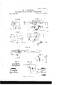
- FIG. 1 is a sideview of the transmitting and receiving apparatus; Fig. 2, a top view.
- Fig. 3 is a sectionalview of the commutator and
- Fig. 4 is a separate view of the receiving apparatus.
- Fig. 5 is a view of the double circuit-changer for working the induction-coils, &c.
- Fig. 6 is shown one of my forms of perforation, being that belonging to the special apparatus, Figs. 1 and 2, and the style of the received message.
- Fig. 1 is a sideview of the transmitting and receiving apparatus
- Fig. 2 a top view.
- Fig. 3 is a sectionalview of the commutator
- Fig. 4 is a separate view of the receiving apparatus.
- Fig. 5 is a view of the double circuit-changer for working the induction-coils, &c.
- Fig. 6 is shown one of my forms of perforation, being that belonging to the special apparatus, Figs. 1 and
- FIG. 7 is a diagram of one method ofv operating the induction-coil with a secondary battery.
- Fig. 8 is a view of the method of perforating paper in application to the ordinary automatic instrument, for forming a special ground, 85c.
- Figs. 9 and 10 are diagrams of circuits.
- Fig. 11 is a view of a non-inductive wire resistance. 7
- A is any suitable metallic frame for holding and supporting the various parts of the apparatus.
- W is the driving wheel fixed to shaft 0 with large gear-wheel G and pulley I, which actuates pulley P fixed to shaft 0 with friction -roller F, for drawing the perforated paper 45 from the reel a on shaft 0 over metallic drum
- D 011 shaft 0 n n are the row of points on shaft 0 which fall through the perforations in the paper. These points are separate, working insulated from each other, and electrically connected, in the order in which they stand, with the levers and rollers f, which are also insulated from each other upon the demicircular frame m.
- the small gear-wheel G, commutator-disk O, and pulley P are fixed to shaft 0.
- Pulley P actuates pulley P, which is fixed to shaft with friction-roller'F, which draws the chemicallyprepared paper h from the reel 0/ over the metallic receiving-drum D and beneath the recording-style d of lever b in standard S
- the commutator disk or wheel G is made of some insulating substance, or so that the metallic pieces 6 and 6 upon its periphery are insulated from the rest of the wheel. There are five pieces 6 and five pieces 0. The five pieces 0 are electrically connected together,
- the five pieces 6 are in like manner connected with the metallic band upon and insulated from the shaft 0.
- the springs K and K, bearing upon the bands j and j, are insulated from the frame and convey the currents proceeding from the comm utatorwheel 0 to the wires.
- the roller of lever f comes between the pieces 6 and e, the pieces 6 and e are electrically connected, which connection is broken when the pieces 0 and e" are carried away from the roller.
- the object of havinga number of pairs of pieces e and e on the commutator-wheel O is to enable the apparatus to pick up the impulses which may proceed from the points a, fallen through the perforations in the paper i very rapidly, without making a revolution of the wheel 0 every time the impulses are gathered .up. For instance, one pair of pieces eand 6 will have passed and made contact with all the rollers f before another pair of pieces 0 and 0 begins to make such contacts. It is obvious that the member of these pairs of pieces may be increased indefinitely.
- a local circuit for a local battery, through the primary wire of an induction-coil, is formed through the drum D, points it, rollers f, and piece 0, which local circuit is broken simultaneously with the removal of the transmitting-battery, and adepolarizing induced current proceeds from the secondary wire of the induction-coil, which is then in the line circuit, and clears the line.
- the local circuit is shown by the dotted line in Fig. 7.
- the secondary wire of the induction-coil is there shown in the line outside of the transmitting-instrument. Instead of being in the line it maybe placed in a shunt, branch, or formed circuit.
- the receiving portion of the instrument, Fig. 4, may be any ordinary appliance for drawing a chemically-prepared fillet of paper under a recording-stylus.
- N and N are two metallic bands, disks, or wheels, insulated from each other, but revolving with the same shaft, which is caused to turn with great rapidity by any suitable mechanism.
- the pieces z are also of metal inlaid, but insulated from the body of the disks. They are of equal numposite each other, but are so arranged that the pieces 2 on one disk are opposite the spaces on the other disk.
- the metallic contact-rollers Q and Q are on a line one with the other, so that when the roller Q is on aspace the roller Q is on an insulated piece, and vice versa.
- the pieces a extend all around the disks, and may be of any number and size.
- the contact-rod ers are held against them by a spring-shaft or any suitable device.
- U U V V are standards, all insulated from each other, but each connected with its contact roller. or disk. 1 is a double-wire inductioncoil, the dotted line representing the primary wire. The coil is placed at any desired point in a branch or sh un t. circuit.
- the operation of the current-changer may be varied in many ways.
- the operation is as follows: One end of the coil-wire is put to earth, and the other end joined 'to the line wire, forming a shunt or branch circuit to the earth, which may be at the receiving end of the line outside the receiving-instrument, and so arranged that the battery-current will divide at the shunt or branch, part of the current passing through the coil to earth, but the greater part passing-through the receivinginstrumen t.
- the circuit-changer is then introduced between the point where the line branches or shunts and the receiving-instrument, when with great rapidity the circuitchanger alternately allows the current to flow and divide, as above specified, and, by introducing a resistance between the shunt or branch and the receiving-instrument, throws a very large proportion of the current through the coil, so as to magnetize the core. Upon the removal of the resistance, the current again flows and divides, as in the first place, and the coil discharges a depolarizing-current into the line, clearing it of tailings.
- the circuit-changer may alternately put the recording-style and the receiving-drum to earth. It may again ground the line at rapid intervals outside the receiving-instrument; or it may break the line at rapid intervals; or it may rapidly introduce into the line and remove from it a resistance; or it may be used to throw a depolarizing-battery into the line, such battery not being strong enough to neutralize the transmittingbattery impulses, but strong enough to neutralize tailings.
- Fig. 10 one method of using the circuit-changer at the receiving end of a line, wherein the transmitting-battery current is alternately allowed to flow straight through the recording style, and diverted through the primary wire of an induction-coil to earth outside the receiving-instrument, the secondary wire of the coil being in a shunt to the recording-style.
- the diverting circuit to earth outside the receiving-instrument is broken, the secondary wire of the coil exerts in the shunt a depolarizing influence upon the recording'style.
- the use of the resistance R is too obvious to, require explanation.
- Fig.7 is shown the main circuit from the transmitting-instrunient and the local circuit and battery for operating the induction-coil P, in which the primary wire may be coarse and of low resistance.
- B is the transmitting-bat *tery; R, an adjustable resistance between it and earth.
- the wire passes from the battery to the drum 1), and, when a contact-point, n, is fallen through a perforation, through such contact-point to the roller f,- thence to piece 6 on commutator-wheel G; thence, through band j on shaft, to spring K, and, through the secondary wire of induction-coil 1 to line.
- I have shown a branch circuit to earth with resistance It between the coil and the instrument.
- The'seconda'ry wire of the coil may, however, be placed in the branch circuit, or in a shunt or derived circuit.
- a local circuit is formed with secondary battery B, which follows nearly the .same course as to the apparatus, as shown by the dotted lines, inducing through the primary wire of the coil'l when the transmitting-battery is removed from the line by a point, a, leaving a perforation, by the same action of a point, 42, leaving a perforation, a depolarizing impulse in the secondary wire of coil 1 and hence the line of any required strength, thus clearing the line of taili-n gs, and rendering the writing at the receiving end clear and distinct.
- Fig. 8 is shown my method of perforating paper and dispensing with a shuntcircuit, by which the battery is greatly weakened.
- the perforating may be done by any of the ordinary perforating-machines, with the necessary alterations in the dies.
- J is the perforated fillet of paper. I11 the lower row of perforations 0 fall the points tr, which have precisely the same function as the roller f and pieces 0 e of- Fig. 7 actuating the induction-coil I in the same manner.
- the battery B between which and the earth there may or may not be an adjustable resistance, R, flows through t, perforations c to drum, and thence to line, there being no shunt-circuit. At the same time the local or secondary battery B is flowing through drum, perforations 0, contact-point r, and primary wire of induction-coil I as shown by the dotted line.
- the secondary wire of induction-coil l is in the wire from earth E to contact-point p, which, when point t leaves perforation c, and just before point 1 leaves the same perforation, drops into perforation 0, and then, when contact-point 1" leaves perforation 0, the primary circuit of the induction-coil is broken and a strong depolarizing influence is exerted upon the line by means of the discharge by the secondary wire of the induction-coil, then in the line-circuit.
- a is the primary and y the secondary wire of the coil.
- R and R are adjustable resistances. The operation is simply as follows: Upon the cessation of an impulse from the transmitting-battery an induced current is set up in the secondary wire of the. coil, which flows through resistances R and R to recording-style of drum D and the induction from the primary wire flows from the coil direct to the recording-style and drum, and back to coil through resistance R thus depolarizing the style.
- Fig. 10 I show the operation of the double circuit-changer, Fig. 5, at the receiving end of a line.
- the circuit is diverted by means of rollerQ and disk it through primary wire of induction-coil I to earth, and this circuit is destroyed, a strong depolarizing effect is produced upon the recording-style by the induced current set up in the secondary wire of the coil in the shunt with resistance R at the breaking of this circuit.
- I also employ thefollowinginethodofproduci n g clear and sharp writing upon the recordin gpaper, usingany of the well-known devices of perforated paper and contact-points for introducin g the currents: .IVhen required to transmit an impulse to be recorded, I first transmit an induced current of the same polarity as the impulse to be recorded; then I transmit the impulse to be recorded direct from battery. I then transmit an induced current of opposite polarity to the impulse recorded, so as to sharpen and cut short the recorded impulse, following this by a battery impulse direct, of opposite polarity to the impulse recorded, in the order thus: Positiveinduced current, positive-battery current, negative induced current, negative-battery current; or I omit the negative-battery current.
- the method'of operating an automatic or chemical telegraph by first simultaneously, or nearly so, closing the transmitting-circuit and the local primary circuit of an induction-coil, and then, upon breaking the transmitting-circuit, and instantly before breaking the local primary circuit, of the induction-coil, closing the circuit of the line through the secondary wire of the induction-coil and to earth, substantially as and for the purposes specified.
- a metallic point, brush, or roller connected or connecting to an induction-coil and to earth, substantially as and for the purposes specified.
- a non-inductive resistance composed of a length of wire arranged in parallel returning layers, substantially as shown and described.
Landscapes
- Engineering & Computer Science (AREA)
- Signal Processing (AREA)
- Computer Networks & Wireless Communication (AREA)
- Charge And Discharge Circuits For Batteries Or The Like (AREA)
Description
w. E SAWYEB. 1 Automatic or Chemical Tglegrap hy.
Patented Jam 5,1875.
o 13 1:13 nus EIEID'CIE) WITNESSES ATTORNEYS.
Fan
JNITED v STATES PATENT OFFICE,
WVILLIAM E SAWYER, OF WASHINGTON, DISTRICT OF COLUMBIA.
IMPROVEMENT IN AUTOMATIC OR CH-VEMICAL TELEGRAPHY.
Specification forming part of Letters Patent No. 158,442, dated January 5, 1875; application filed November 10, 1874.
To all whom it may concern:
Be it known that I, WILLIAM E. SAWYER, of the city of Washington, in the District of Columbia, have invented a new and Improved System of Automatic Chemical Telegraph, comprising transmitting and receiving instruments, circuits, and apparatus connected therewith, of which the following is a specification:
Many of the features of my invention are comprised in an application filed by me on the 19th day of October, 1874, for a fac-simile telegraph, styled the new pantelegraph, the use of which in an automatic chemical telegraph was alluded to in my specification of that date. It is my design to apply any of the principles of either invention to the operation of the other. In a portion of my present invention I make use of the commutating principle of the new pantelegraph in the transmitting apparatus, whereby I am enabled to make perfect electrical contact by means of metallic points, brushes, or rollers falling through perforations in a sheet or strip of paper at a speed of transmission which would greatly imperil if not absolutely pre vent perfect contacts in present automatic systems, and whereby I am also enabled to change a line of wire without surcharging it, thus enabling a line to sooner free itself, and, in great measure, preventing or avoiding tailin gs. This will be obvious upon reference to the commutator shown in the accompanying drawings. The form of the commutator may be varied in many ways, but its principle is essentially the same as that shown and described in the drawings and specification of my fac-simile telegraph.
To carry the com mutating principle into effect, I employ a strip, sheet, or roll of paper perforated crosswise, so as to read as any ordinary printed page, through the perforations of which drop a row, comprising any number, of metallic points or rollers, insulated from each other, which metallic points or rollers,
consecutively, by means of the commutating band or disk and contact'rollers, are brought into the circuit of linewire, battery, and earth, thus accomplishing an indefinite speed of transmission of impulses, by means of theperforated paper, with an indefinite slowness of motion of the perforated paper. The message is received upon a fillet of chemicallyprepared paper, as in the ordinary automatic telegraph.
For producing the chemical discoloration necessary to recording a message I use the current from the main battery, but for clearing the line of tailings or positive inductive efl'ects I employ the brief intensity impulse resulting from induction, which I produce by a local circuit and battery operated by the row of contact-points upon the perforated paper and the commutator wheel and rollers. I have shown in my drawings double insulated pieces of metal upon the commutator-wheel, so arranged that, in revolving under the rollers, the double pieces are electrically united, but I do not confine myself to such an arrangement. In many cases two or more rollers, as well as double pieces upon the commutator-wheel, may be preferable. Nor do I confine myself to the arrangement of the rollers with relation to the pieces upon the commutator-wheel. The positions may be reversed, so that the contact-points upon the perforated paper shall be connected with pieces upon the commutator wheel, band, or disk, instead of, as shown, with the rollers. More pieces than two upon the commutatorwheel, and a greater number of contact-rollers than is shown, may be employed for purposes connected with inductive effects, and putting the line to earth otherwise than through the battery. I do not, in fact, limit myself to any of the special forms and contrivances shown and described. The contact rollers of the commutator-wheel, although in less number, for instance, may be as large in diameter as the commutator-wheel itself, and other like deviations from my plan may be made use of.
I am aware that magnetic induction produced in a shunt or derived circuit has been employed for the purpose of clearing a line of tailings; but I am not aware that an ordinary induction-coil, consisting of a coarse primary wire and a relatively-fine secondary wire surrounding a bundle of line ironwires, has been used for that purpose. I employ a doublewire induction-coil similar to the foregoing at any point in the line or in a shunt or branch circuit, and I cause it to produce depolarizing effects independently of the cessation or decrement of the impulses proceeding from the battery, as well as dependent upon them.
In my fac-simile drawings and specifications I have shown a method of causing the coil to act by diverting the current to earth outside the receiving-instrument.
In arranging the induction apparatus to meet the requirements of a line which is subject to constant changes in electrical condition, it is desirable to be able to increase or diminish with facility both the resistances of the coils and the inductive effects from the magnetized -iron cores, which may be in any form of bar-iron or Wire, straight or coiled wire, or wire in layers, pieces, or single lengths; hence I employ a case of coils or spools of various lengths with suitable switches, and iron cores of various lengths and diameters, which are withdrawn from or introduced into the coils in the same manner as the connecting-plugs of. Bradleys resistance-box accompanying the well-known Bradley tangent galvanometer.
Having thus generally described my invention, and in order to enable those skilled in the art to make and use my improvements, I will describe the same more in detail, reference being had to the accompanying drawings forming part of this specification, in which- Figure 1 is a sideview of the transmitting and receiving apparatus; Fig. 2, a top view. Fig. 3 is a sectionalview of the commutator and Fig. 4 is a separate view of the receiving apparatus. Fig. 5 is a view of the double circuit-changer for working the induction-coils, &c. In Fig. 6 is shown one of my forms of perforation, being that belonging to the special apparatus, Figs. 1 and 2, and the style of the received message. Fig. 7 is a diagram of one method ofv operating the induction-coil with a secondary battery. Fig. 8 is a view of the method of perforating paper in application to the ordinary automatic instrument, for forming a special ground, 85c. Figs. 9 and 10 are diagrams of circuits. Fig. 11 is a view of a non-inductive wire resistance. 7
Like letters indicate similar parts in all of the figures.
A is any suitable metallic frame for holding and supporting the various parts of the apparatus. W is the driving wheel fixed to shaft 0 with large gear-wheel G and pulley I, which actuates pulley P fixed to shaft 0 with friction -roller F, for drawing the perforated paper 45 from the reel a on shaft 0 over metallic drum D 011 shaft 0 n n are the row of points on shaft 0 which fall through the perforations in the paper. These points are separate, working insulated from each other, and electrically connected, in the order in which they stand, with the levers and rollers f, which are also insulated from each other upon the demicircular frame m.
w The small gear-wheel G, commutator-disk O, and pulley P are fixed to shaft 0. Pulley P actuates pulley P, which is fixed to shaft with friction-roller'F, which draws the chemicallyprepared paper h from the reel 0/ over the metallic receiving-drum D and beneath the recording-style d of lever b in standard S The commutator disk or wheel G is made of some insulating substance, or so that the metallic pieces 6 and 6 upon its periphery are insulated from the rest of the wheel. There are five pieces 6 and five pieces 0. The five pieces 0 are electrically connected together,
and with the metallic band j, which is insulated from shaft 0. The five pieces 6 are in like manner connected with the metallic band upon and insulated from the shaft 0. The springs K and K, bearing upon the bands j and j, are insulated from the frame and convey the currents proceeding from the comm utatorwheel 0 to the wires. As the roller of lever f comes between the pieces 6 and e, the pieces 6 and e are electrically connected, which connection is broken when the pieces 0 and e" are carried away from the roller. The object of havinga number of pairs of pieces e and e on the commutator-wheel O is to enable the apparatus to pick up the impulses which may proceed from the points a, fallen through the perforations in the paper i very rapidly, without making a revolution of the wheel 0 every time the impulses are gathered .up. For instance, one pair of pieces eand 6 will have passed and made contact with all the rollers f before another pair of pieces 0 and 0 begins to make such contacts. It is obvious that the member of these pairs of pieces may be increased indefinitely.
Although I have shown the commutator parts sectionally in Fig. 3, and the receiving parts separately in Fig. 4:, I have only done so in order to show clearly the nature of the apparatus.
The connections between the points a and rollers f will be understood from the ends of the wires cut off, proceeding from each. The method of perforating the paper for this form of transmitter is obvious from Fig. 6, in which J is a piece of a roll or strip of paper with the perforations in dots and dashes. The message reads across the roll or strip of paper, as any ordinary printed page. The lines of perforations are but slightly separated, and at such an angle as would cause the end of one line to connect upon the same inclination with the beginning of the succeeding line, supposing the left and right hand sides of the roll to be' brought together; in .other words, the lines form what might be termed a plane spiral. The message is not, however, recorded in the same form, but, in the usual way, upon a continuous fillet of chemically-prepared paper, as shown by L.
I have not shown any apparatus for perforating the paper, as the perforation may be accomplished by any of the ordinary perforating-mac'hines,with the dies altered to suitthe character of my perforations, and some additional mechanism for giving the sheet or roll of paper the necessary dual motion-4. 6., forward and upward.
\ The operation of transmission is as follows: When one of the points a is fallen through a perforation, the contact-roller f, connected with such point, is put to the battery by means of the'connection then existing with the drum D, and when one of the pieces 6 comes under such roller the battery is thrown upon the line and continues upon the line as long as the roller f remains in contact with the piece 6, which ofcourse is an instant only. This is the whole process of transmission of battery impulses. In the case of a dot-transmission there would be only one of the points a and rollers f in contact with the drum 1), and therefore the battery would be upon the line only long enough to form a dot upon the ordinary inoving chemical paper at the receiving end of the line. In the case of a dash, two or three of the points a would fall through the perforation to the drum 1), and consequently the battery would be putto as many of the rollers f in succession, so that the piece 0 will no sooner have left one roller f, transmitting the battery, than it will come under another roller f continuing the transmission, thus forming a dash at the receiving end. At the same time that the transmitting-battery is flowing through a piece 0, a local circuit for a local battery, through the primary wire of an induction-coil, is formed through the drum D, points it, rollers f, and piece 0, which local circuit is broken simultaneously with the removal of the transmitting-battery, and adepolarizing induced current proceeds from the secondary wire of the induction-coil, which is then in the line circuit, and clears the line.
The local circuit is shown by the dotted line in Fig. 7. The secondary wire of the induction-coil is there shown in the line outside of the transmitting-instrument. Instead of being in the line it maybe placed in a shunt, branch, or formed circuit.
It will be obvious that, as the friction-roller F is turning as long as the commutator O is revolving, the spirally-perforated paper, Fig. 6, will be continuously drawn over the drum D, and the impulses corresponding to the perforations transmitted. The receiving portion of the instrument, Fig. 4, may be any ordinary appliance for drawing a chemically-prepared fillet of paper under a recording-stylus.
In the drawing the paper is shown as being drawn over the receiving-drum D by the frietion-roller F, operated by pulleys.
The double circuit-changer, Fig. 5, is an important adjunct to my system. N and N are two metallic bands, disks, or wheels, insulated from each other, but revolving with the same shaft, which is caused to turn with great rapidity by any suitable mechanism. The pieces z are also of metal inlaid, but insulated from the body of the disks. They are of equal numposite each other, but are so arranged that the pieces 2 on one disk are opposite the spaces on the other disk.
The metallic contact-rollers Q and Q, however, are on a line one with the other, so that when the roller Q is on aspace the roller Q is on an insulated piece, and vice versa. The pieces a extend all around the disks, and may be of any number and size. The contact-rod ers are held against them by a spring-shaft or any suitable device. U U V V are standards, all insulated from each other, but each connected with its contact roller. or disk. 1 is a double-wire inductioncoil, the dotted line representing the primary wire. The coil is placed at any desired point in a branch or sh un t. circuit.
The manner in which the coil operates is obvious from the arrangement of the wires.
When the roller Q is in contact with the metal of the disk N, the current flows-say,
from the line-wire L W to the left-through standard U to disk-roller Q to standard V, and through one of the wires of the coil l to the resistance It and earth E at the right, thus sending a portion of the line-current to earth outside the receiving-instrument. When the roller Q touches a piece, 2, this circuit is broken, and a depolarizing impulse is thrown into the line through the other wire, which is then in circuit-say, from the left-through the other wire of the coil to standard V, roller Q, disk N, standard U, and resistance and earth to the right. By this arrangement the line is maintained in constant equilibrium as to electrical condition, and at the cessation of an impulse from the sending-battery the attenuation or tailing of the current is instantly neutralized, and the writing comes sharp and distinct.
The operation of the current-changer may be varied in many ways.
Assuming that a single wire in a coil surrounding a bar or bars of iron, or a bundle of iron wires, is used, the operation is as follows: One end of the coil-wire is put to earth, and the other end joined 'to the line wire, forming a shunt or branch circuit to the earth, which may be at the receiving end of the line outside the receiving-instrument, and so arranged that the battery-current will divide at the shunt or branch, part of the current passing through the coil to earth, but the greater part passing-through the receivinginstrumen t. The circuit-changer is then introduced between the point where the line branches or shunts and the receiving-instrument, when with great rapidity the circuitchanger alternately allows the current to flow and divide, as above specified, and, by introducing a resistance between the shunt or branch and the receiving-instrument, throws a very large proportion of the current through the coil, so as to magnetize the core. Upon the removal of the resistance, the current again flows and divides, as in the first place, and the coil discharges a depolarizing-current into the line, clearing it of tailings.
In'another case the circuit-changer may alternately put the recording-style and the receiving-drum to earth. It may again ground the line at rapid intervals outside the receiving-instrument; or it may break the line at rapid intervals; or it may rapidly introduce into the line and remove from it a resistance; or it may be used to throw a depolarizing-battery into the line, such battery not being strong enough to neutralize the transmittingbattery impulses, but strong enough to neutralize tailings.
l have shown at Fig. 10 one method of using the circuit-changer at the receiving end of a line, wherein the transmitting-battery current is alternately allowed to flow straight through the recording style, and diverted through the primary wire of an induction-coil to earth outside the receiving-instrument, the secondary wire of the coil being in a shunt to the recording-style. When the diverting circuit to earth outside the receiving-instrument is broken, the secondary wire of the coil exerts in the shunt a depolarizing influence upon the recording'style. The use of the resistance R is too obvious to, require explanation.
In Fig.7 is shown the main circuit from the transmitting-instrunient and the local circuit and battery for operating the induction-coil P, in which the primary wire may be coarse and of low resistance. B is the transmitting-bat *tery; R, an adjustable resistance between it and earth. The wire passes from the battery to the drum 1), and, when a contact-point, n, is fallen through a perforation, through such contact-point to the roller f,- thence to piece 6 on commutator-wheel G; thence, through band j on shaft, to spring K, and, through the secondary wire of induction-coil 1 to line. I have shown a branch circuit to earth with resistance It between the coil and the instrument. The'seconda'ry wire of the coil may, however, be placed in the branch circuit, or in a shunt or derived circuit. At the same time that a current is passing over the line in the circuit described, a local circuit is formed with secondary battery B, which follows nearly the .same course as to the apparatus, as shown by the dotted lines, inducing through the primary wire of the coil'l when the transmitting-battery is removed from the line by a point, a, leaving a perforation, by the same action of a point, 42, leaving a perforation, a depolarizing impulse in the secondary wire of coil 1 and hence the line of any required strength, thus clearing the line of taili-n gs, and rendering the writing at the receiving end clear and distinct.
In Fig. 8 is shown my method of perforating paper and dispensing with a shuntcircuit, by which the battery is greatly weakened.
The perforating may be done by any of the ordinary perforating-machines, with the necessary alterations in the dies.
In this I use three metallic contact-points, brushes, or rollers, 17 'r t, arranged as indicated by the drawing, for making connections through the perforations.
1 have deemed it unnecessary to show more than the transmittting-drum D and contact points or rollers, as the principles and appa- 'ratus of ordinary automatic systems are well understood.
J is the perforated fillet of paper. I11 the lower row of perforations 0 fall the points tr, which have precisely the same function as the roller f and pieces 0 e of- Fig. 7 actuating the induction-coil I in the same manner. The battery B, between which and the earth there may or may not be an adjustable resistance, R, flows through t, perforations c to drum, and thence to line, there being no shunt-circuit. At the same time the local or secondary battery B is flowing through drum, perforations 0, contact-point r, and primary wire of induction-coil I as shown by the dotted line.
The secondary wire of induction-coil l is in the wire from earth E to contact-point p, which, when point t leaves perforation c, and just before point 1 leaves the same perforation, drops into perforation 0, and then, when contact-point 1" leaves perforation 0, the primary circuit of the induction-coil is broken and a strong depolarizing influence is exerted upon the line by means of the discharge by the secondary wire of the induction-coil, then in the line-circuit.
- My method of putting a double-wire induction-coil in a shunt-in-shunt circuit at the receiving end of a line is shown in Fig. 9, where a; is the primary and y the secondary wire of the coil. 1%, R and R are adjustable resistances. The operation is simply as follows: Upon the cessation of an impulse from the transmitting-battery an induced current is set up in the secondary wire of the. coil, which flows through resistances R and R to recording-style of drum D and the induction from the primary wire flows from the coil direct to the recording-style and drum, and back to coil through resistance R thus depolarizing the style. I prefer to employ as resistances 'sulphuric acid diluted to one-eleventh, and nitric acid. I also employ for slight or even high resistances insulated lead wire in straight parallel returning layers'R, Fig. 11,.inst'ead of coils, for the purpose of neutralizing inductive effects.
In operating ocean-cables it is of advantage to employequating-batteries of both polarities, which are introduced into the cable at the receiving end, as occasion may require, by any suitable device. When-the recording-style is making a continuous mark it is evident that the cable contains a surplus of the discoloringcurrent, and the receiving operator thereupon introduces a neutralizing-current to clear the line. When the recording-style is marking imperfectly it is evident that the depolarizingcharge in the cable is too strong, and the receiving operator introduces a current of the same polarity as the discoloring-current.
By using a magnifying-glass the increment and decrement of the currents, as indicated by the marks upon the chemical paper growin g darker or lighter, may be more easily noted and the proper neutralizing-batteries introduced accordingly. As any one of many devices will accomplish the same thing, and the process is not capable of illustration, I have not attempted by drawings to indicate the magnifying-glass, or its position at the receiving-instrument or devices for introducing neutralizingbatteries. By its use a very high rate of speed for cables may be attained. It will be understood that the neutralizingbatteries are kept upon the cable only long enough to render the writing clear, and that they may be of different strengths or powers.
In Fig. 10 I show the operation of the double circuit-changer, Fig. 5, at the receiving end of a line. When the circuit is diverted by means of rollerQ and disk it through primary wire of induction-coil I to earth, and this circuit is destroyed, a strong depolarizing effect is produced upon the recording-style by the induced current set up in the secondary wire of the coil in the shunt with resistance R at the breaking of this circuit.
I also employ thefollowinginethodofproduci n g clear and sharp writing upon the recordin gpaper, usingany of the well-known devices of perforated paper and contact-points for introducin g the currents: .IVhen required to transmit an impulse to be recorded, I first transmit an induced current of the same polarity as the impulse to be recorded; then I transmit the impulse to be recorded direct from battery. I then transmit an induced current of opposite polarity to the impulse recorded, so as to sharpen and cut short the recorded impulse, following this by a battery impulse direct, of opposite polarity to the impulse recorded, in the order thus: Positiveinduced current, positive-battery current, negative induced current, negative-battery current; or I omit the negative-battery current.
What I claim as new, and desire to secure by Letters Patent, is
1. A sheet, roll, or strip of paper, perforated for telegraphic transmission, in lines running from left to right, as in an ordinary printed 3. The combination, with a line, its battery and contactpoint brush or roller therefor, or an induction-coil and contact-point brush or roller therefor connecting the line to, earth, and throwing the secondary induced current into the line, for the purpose of clearing the same of tailings, as set forth.
4. The combination, witha line and its transmitting-battery, of an induction-coil, the secondary current from which is thrown into the line immediately after each signaling-pulsation, substantially as described.
5. The method'of operating an automatic or chemical telegraph by first simultaneously, or nearly so, closing the transmitting-circuit and the local primary circuit of an induction-coil, and then, upon breaking the transmitting-circuit, and instantly before breaking the local primary circuit, of the induction-coil, closing the circuit of the line through the secondary wire of the induction-coil and to earth, substantially as and for the purposes specified.
6. In combination with the main-line circuit, a metallic point, brush, or roller connected or connecting to an induction-coil and to earth, substantially as and for the purposes specified.
7. The combination of a metallic point, brush, or roller closing the circuit of a local battery through the primary Wire of an induction-coil, and a metallic point, brush, or
roller closing the circuit of the secondary wire thereof to the line, the local circuit being broken at or just after the completion of the secondary-wire circuit, asset forth.
8. In a chemical-telegraph receiving-instrument, the combination, with a shunt within a shunt circuit, of the primary and secondary wires of an induction-coil and resistances, as set forth.
9. A non-inductive resistance, composed of a length of wire arranged in parallel returning layers, substantially as shown and described.
10. The combination, with a line or circuit, of acommutator, or circuit-changer or currentdiverter, and two series of apparatus or bat teries composed of different parts or sections or two circuits, or two parts of one apparatus or battery, the series, parts or sections, or circuits referred to being alternately connected to the line by the commutator, substantially as and for the purposes specified.
11. In chemical telegraphs, the method of producing a clear sharp record, assuming a positive-battery current to be the impulse to be recorded, by charging the line in the fol-
Publications (1)
| Publication Number | Publication Date |
|---|---|
| US158442A true US158442A (en) | 1875-01-05 |
Family
ID=2227852
Family Applications (1)
| Application Number | Title | Priority Date | Filing Date |
|---|---|---|---|
| US158442D Expired - Lifetime US158442A (en) | Improvement in automatic or chemical telegraphy |
Country Status (1)
| Country | Link |
|---|---|
| US (1) | US158442A (en) |
Cited By (1)
| Publication number | Priority date | Publication date | Assignee | Title |
|---|---|---|---|---|
| US2993812A (en) * | 1959-05-26 | 1961-07-25 | American Viscose Corp | Perforated tape |
-
0
- US US158442D patent/US158442A/en not_active Expired - Lifetime
Cited By (1)
| Publication number | Priority date | Publication date | Assignee | Title |
|---|---|---|---|---|
| US2993812A (en) * | 1959-05-26 | 1961-07-25 | American Viscose Corp | Perforated tape |
Similar Documents
| Publication | Publication Date | Title |
|---|---|---|
| US1310719A (en) | Secret signaling system | |
| US158442A (en) | Improvement in automatic or chemical telegraphy | |
| US1970424A (en) | High frequency signal system | |
| US752923A (en) | No model | |
| US165620A (en) | Improvement in automatic electric telegraphs | |
| US255332A (en) | Charles a | |
| US704023A (en) | Telegraph. | |
| US285710A (en) | Bekgh | |
| US861125A (en) | Simultaneous transmission of telegraphic and telephonic impulses. | |
| US551947A (en) | Electric telegraph | |
| US1601940A (en) | Telegraph system | |
| US583026A (en) | System of telegraphy | |
| US850858A (en) | Emergency-telegraph. | |
| US466492A (en) | facer | |
| US796596A (en) | Electric telegraphy. | |
| US775416A (en) | Electric system of transmission. | |
| US1219110A (en) | Method of and means for quadruplexing cables. | |
| US235160A (en) | Oeazio lugo | |
| US426819A (en) | Francis w | |
| US1012231A (en) | Telegraphy. | |
| US199869A (en) | Improvement in duplex telegraphs | |
| US135531A (en) | Improvement in circuits for chemical telegraphs | |
| US1221814A (en) | Electric-telegraph system. | |
| US153309A (en) | Improvement in electric-telegraph apparatus | |
| US189184A (en) | Improvement in automatic telegraphy |