US1580098A - Tilting frame - Google Patents
Tilting frame Download PDFInfo
- Publication number
- US1580098A US1580098A US697880A US69788024A US1580098A US 1580098 A US1580098 A US 1580098A US 697880 A US697880 A US 697880A US 69788024 A US69788024 A US 69788024A US 1580098 A US1580098 A US 1580098A
- Authority
- US
- United States
- Prior art keywords
- cage
- frame
- supporting
- members
- secured
- Prior art date
- Legal status (The legal status is an assumption and is not a legal conclusion. Google has not performed a legal analysis and makes no representation as to the accuracy of the status listed.)
- Expired - Lifetime
Links
Images
Classifications
-
- B—PERFORMING OPERATIONS; TRANSPORTING
- B67—OPENING, CLOSING OR CLEANING BOTTLES, JARS OR SIMILAR CONTAINERS; LIQUID HANDLING
- B67C—CLEANING, FILLING WITH LIQUIDS OR SEMILIQUIDS, OR EMPTYING, OF BOTTLES, JARS, CANS, CASKS, BARRELS, OR SIMILAR CONTAINERS, NOT OTHERWISE PROVIDED FOR; FUNNELS
- B67C9/00—Devices for emptying bottles, not otherwise provided for
Definitions
- This invention relatesto tilting frames or supports for bottles, and similar containers,
- An object of the present invention is the provision of an improved locking means for A further object is the provision of a collapsible cage adapted to be pivotally supported on the frame and to receive a bottle or similar container.
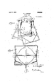
- Figure 1 is a perspective View of one form of the invention
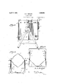
- Figure 2 is a plan View
- Figure 8 is a side elevation
- Figure 4 is a plan view of the cage in folded position
- Figure 51 s a slmilar view of the supporting frame folded
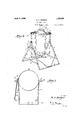
- Figure .6 is a perspectiveview showing a cage to be used with round bottles
- Figure 7 is a plan View of the cage shown in Figure 6.
- the reference numeral 1 designates generally one ofthe members of the supporting frame.
- the supporting frame is formed of two members, each of which is substantially U-shaped and comprises a base 2 and arms 3.
- the adjacent arms of each section of the frame arearranged'at an angle to each other when in assembled position, forming a triangular support. These arms are connected by links 4, pivotally connected to the arms.
- a latch 5 is secured to one of the arms adjacent its .upper end and the latch is provided with a recess 6, adapted to receive a pin 7 carried by the other arm to- In the form of the invention shown in this ring. 7 secured to each other by a rivet 23.
- the cage is substantially rectangular in cross section, and is adapted to receive a rectangular (5011-, I tainer.
- the cage consists of an upper member 11 having a pair'of dependto, and arranged at right angles to each other.
- the supporting members are substantially U-shaped and are connected toeach other by a bolt or .rivetlS.
- the armsof one ing supporting members 12 secured thereof the supporting members are secured to the v Imember 11 by rivets 14 and the arms of the other member are secured to the member 11 by removable nuts 15 and b0ltsf 16.
- ,hoolr17 is connected to a coil spring 18 carried by one of the supporting members 12 and this hook is adapted to engage thetop of a can 19.
- the pins 10 which are received in the notches 9, are carried by the arms of one of the members 12, whereby the cage is permitted to swing about these pins as an axis to discharge the con-' tents of the ca'n..19.-
- Substantially vc-shaped members 18 are secured to the arms of one of the supporting members 12, by pins or rivets 19.
- V-shaped members en-J gage the corners of a square can to retain I it in position, and also permit the use of a rectangular cage for supporting round bottles.
- the member 11 is replaced by a ring'20'and a pair of supporting members 21 and 22 are secured to These supporting members are supporting member 21 is secured to the ring 20 by means of rivets 24 and the supporting member 22 is secured thereto by bolts 25 and nuts 26. 1 c
- the supporting'frame may be ,7
- a bottle 27 is illustrated, having a neck 28 and in place of the hook 17, I employ a chain 29, which is adapted to surround the neck of the bottle, and provided with an extending end connected to the supporting member 21, as indicated at 30.
- a support for liquid containers comprising a skeleton frame, a cage removably supported in said frame, said cage comprising an upper member adapted to surround a container arranged therein, a member depending therefrom and having a portion adapted to be arranged beneath the con tainer, a second depending member removably secured to sald upper member having a portion adapted to be arranged beneath the container and connected tothe lower portion of said first member whereby said cage-may be collapsed and the parts arranged in a single plane, and substantially V-sha-ped members secured to one of said depending members and adapted to engage the sides of the container.
- a support for liquid containers comprising a skeleton frame, a cage removably supported in said frame, said cage comprising an upper member adapted to surround a container therein, a member depending therefrom and having a portion adapted to be arranged beneath the container, and ⁇ a second depending member removably secured to said upper member having a portion adapted to be arranged beneath the container and connected to the lower portion of said first mentioned member whereby said cage may be collapsed and the parts arranged in a. single plane.
Landscapes
- Filling Of Jars Or Cans And Processes For Cleaning And Sealing Jars (AREA)
Description
B. A. BERGER April 6 1926.
TILTING FRAME 3 Sheets-Sheet 1 Filed March a, 1924 April 6 1926. 1,580,098
B.- A. BERGER TILTING FRAME Filed March 8, 1924 3 Sheets-Sheet 2 gwvemto c ,B. A. Bayer thesupporting frame.
Patented Apr. 6, 1926.
' UNITED sTATEi-S 1,580,098 PATENT OFFICE.
BRUNO A. BERGER, 0F RICHMOND, VIRGINIA, AssIeNoR'To BERGER SPECIALTY" MANUFACTURING COMPANY, INC., OF RICHMOND, VIRGINIA, A CORPORATION OF VIRGINIA.
TILTING FRAME.
Applicationiiled March, 8, 1924. SeriaI No. 697,880.
7 To all whom it may concern:
Be it known that I, BRUNO A. BERGE a citizen of the United States, residing in the city of Richmond and State of, Virginia, have invented certain new and useful Improvements in Tilting Frames, of which the following is a specification.
This invention relatesto tilting frames or supports for bottles, and similar containers,
and is an improvement over the construction.
described and claimed in my prior Patent No. 1,188,610, granted June 27, 1916. r b
An object of the present invention is the provision of an improved locking means for A further object is the provision of a collapsible cage adapted to be pivotally supported on the frame and to receive a bottle or similar container.
In the accompanying drawings, I have shown several embodiments of the invention. In thisshowing: V
Figure 1 is a perspective View of one form of the invention,
Figure 2 is a plan View,
Figure 8 is a side elevation,
Figure 4: is a plan view of the cage in folded position,
Figure 51s a slmilar view of the supporting frame folded,
Figure .6 is a perspectiveview showing a cage to be used with round bottles,
Figure 7 is a plan View of the cage shown in Figure 6.
Referring to the drawings, the reference numeral 1 designates generally one ofthe members of the supporting frame. As shown, the supporting frame is formed of two members, each of which is substantially U-shaped and comprises a base 2 and arms 3. The adjacent arms of each section of the frame arearranged'at an angle to each other when in assembled position, forming a triangular support. These arms are connected by links 4, pivotally connected to the arms. A latch 5 is secured to one of the arms adjacent its .upper end and the latch is provided with a recess 6, adapted to receive a pin 7 carried by the other arm to- In the form of the invention shown in this ring. 7 secured to each other by a rivet 23. The
Figures 1 to 5 of the drawings, the cage is substantially rectangular in cross section, and is adapted to receive a rectangular (5011-, I tainer. I As shown, the cage consists of an upper member 11 having a pair'of dependto, and arranged at right angles to each other. The supporting members are substantially U-shaped and are connected toeach other by a bolt or .rivetlS. The armsof one ing supporting members 12 secured thereof the supporting members are secured to the v Imember 11 by rivets 14 and the arms of the other member are secured to the member 11 by removable nuts 15 and b0ltsf 16. "A
,hoolr17 is connected to a coil spring 18 carried by one of the supporting members 12 and this hook is adapted to engage thetop of a can 19. As shown, the pins 10 which are received in the notches 9, are carried by the arms of one of the members 12, whereby the cage is permitted to swing about these pins as an axis to discharge the con-' tents of the ca'n..19.- Substantially vc-shaped members 18are secured to the arms of one of the supporting members 12, by pins or rivets 19.
These V-shaped members en-J gage the corners of a square can to retain I it in position, and also permit the use of a rectangular cage for supporting round bottles.
vIn the .form of the invention shown in Figures 6 and 7 of the drawings, the member 11 is replaced by a ring'20'and a pair of supporting members 21 and 22 are secured to These supporting members are supporting member 21 is secured to the ring 20 by means of rivets 24 and the supporting member 22 is secured thereto by bolts 25 and nuts 26. 1 c
The operation of the device will be readily apparent. The supporting'frame may be ,7
connecting the members'to each other with;
the bases arranged at the opposite ends of the collapsed frame. To collapse the cage shown in Figures 1 to 5 of the drawings, the
I claim:
1., A support for liquid containers comprising a skeleton frame, a cage removably supported in said frame, said cage comprising an upper member adapted to surround a container arranged therein, a member depending therefrom and having a portion adapted to be arranged beneath the con tainer, a second depending member removably secured to sald upper member having a portion adapted to be arranged beneath the container and connected tothe lower portion of said first member whereby said cage-may be collapsed and the parts arranged in a single plane, and substantially V-sha-ped members secured to one of said depending members and adapted to engage the sides of the container.
2. A support for liquid containers comprising a skeleton frame, a cage removably supported in said frame, said cage comprising an upper member adapted to surround a container therein, a member depending therefrom and having a portion adapted to be arranged beneath the container, and {a second depending member removably secured to said upper member having a portion adapted to be arranged beneath the container and connected to the lower portion of said first mentioned member whereby said cage may be collapsed and the parts arranged in a. single plane.
In testimony whereof I afiiX my signature.
BRUNO A. BERGER.
Priority Applications (1)
| Application Number | Priority Date | Filing Date | Title |
|---|---|---|---|
| US697880A US1580098A (en) | 1924-03-08 | 1924-03-08 | Tilting frame |
Applications Claiming Priority (1)
| Application Number | Priority Date | Filing Date | Title |
|---|---|---|---|
| US697880A US1580098A (en) | 1924-03-08 | 1924-03-08 | Tilting frame |
Publications (1)
| Publication Number | Publication Date |
|---|---|
| US1580098A true US1580098A (en) | 1926-04-06 |
Family
ID=24802967
Family Applications (1)
| Application Number | Title | Priority Date | Filing Date |
|---|---|---|---|
| US697880A Expired - Lifetime US1580098A (en) | 1924-03-08 | 1924-03-08 | Tilting frame |
Country Status (1)
| Country | Link |
|---|---|
| US (1) | US1580098A (en) |
Cited By (4)
| Publication number | Priority date | Publication date | Assignee | Title |
|---|---|---|---|---|
| US2605071A (en) * | 1948-01-12 | 1952-07-29 | Alfred H C Trepte | Collapsible dispensing rack |
| US2708558A (en) * | 1951-11-19 | 1955-05-17 | John N Pedersen | Tiltable container holder and stand |
| US2813693A (en) * | 1955-05-06 | 1957-11-19 | Albert L Puddicombe | Pouring stands for liquid containers |
| US3201074A (en) * | 1963-08-15 | 1965-08-17 | Charles R Stearns | Tiltable pouring cradle |
-
1924
- 1924-03-08 US US697880A patent/US1580098A/en not_active Expired - Lifetime
Cited By (4)
| Publication number | Priority date | Publication date | Assignee | Title |
|---|---|---|---|---|
| US2605071A (en) * | 1948-01-12 | 1952-07-29 | Alfred H C Trepte | Collapsible dispensing rack |
| US2708558A (en) * | 1951-11-19 | 1955-05-17 | John N Pedersen | Tiltable container holder and stand |
| US2813693A (en) * | 1955-05-06 | 1957-11-19 | Albert L Puddicombe | Pouring stands for liquid containers |
| US3201074A (en) * | 1963-08-15 | 1965-08-17 | Charles R Stearns | Tiltable pouring cradle |
Similar Documents
| Publication | Publication Date | Title |
|---|---|---|
| US2397716A (en) | Bottle carrier | |
| US2501572A (en) | Skillet and kettle combination | |
| US1580098A (en) | Tilting frame | |
| US1669300A (en) | Knockdown receptacle | |
| US2303240A (en) | Bottle carrier | |
| US1779060A (en) | Carrier for containers | |
| US2315001A (en) | Collapsible frame for cellophane display boxes | |
| US2333954A (en) | Bottle carrier | |
| US2632578A (en) | Collapsible container | |
| US2223554A (en) | Stacking handle for pin boards and cone boards | |
| US1609207A (en) | Foldable holder and manipulator for bottles | |
| US2614700A (en) | Rack for milk buckets or like containers | |
| US2745675A (en) | Basket carrying cart | |
| US1724385A (en) | Display stand | |
| US2375467A (en) | Bottle case | |
| US2073155A (en) | Basket stand | |
| US2671566A (en) | Display rack | |
| US1453547A (en) | Barrel-holding device | |
| US1784240A (en) | Collapsible basket support | |
| US1460554A (en) | Device for carrying baskets and the like | |
| US2404532A (en) | Bottle carrier | |
| US2844279A (en) | Folding carrier for bottles | |
| US2432351A (en) | Bottle carrier | |
| US1411805A (en) | Foldable trestle | |
| US951916A (en) | Cover-holder for cans. |