US1574438A - Wrapping machine - Google Patents
Wrapping machine Download PDFInfo
- Publication number
- US1574438A US1574438A US685325A US68532524A US1574438A US 1574438 A US1574438 A US 1574438A US 685325 A US685325 A US 685325A US 68532524 A US68532524 A US 68532524A US 1574438 A US1574438 A US 1574438A
- Authority
- US
- United States
- Prior art keywords
- shuttle
- machine
- brake
- wrapping machine
- gap
- Prior art date
- Legal status (The legal status is an assumption and is not a legal conclusion. Google has not performed a legal analysis and makes no representation as to the accuracy of the status listed.)
- Expired - Lifetime
Links
- 230000015572 biosynthetic process Effects 0.000 description 9
- 238000003780 insertion Methods 0.000 description 3
- 230000037431 insertion Effects 0.000 description 3
- 238000012986 modification Methods 0.000 description 1
- 230000004048 modification Effects 0.000 description 1
Images


Classifications
-
- B—PERFORMING OPERATIONS; TRANSPORTING
- B65—CONVEYING; PACKING; STORING; HANDLING THIN OR FILAMENTARY MATERIAL
- B65H—HANDLING THIN OR FILAMENTARY MATERIAL, e.g. SHEETS, WEBS, CABLES
- B65H81/00—Methods, apparatus, or devices for covering or wrapping cores by winding webs, tapes, or filamentary material, not otherwise provided for
- B65H81/02—Covering or wrapping annular or like cores forming a closed or substantially closed figure
- B65H81/04—Covering or wrapping annular or like cores forming a closed or substantially closed figure by feeding material obliquely to the axis of the core
Definitions
- ERANx M RIERCE, OE CHICAGO, ILLINOIS, AssIeNoR To MERCE WRAPIING MA- CHINE COMPANY, or CHICAGO, ILLINOIS, A CORPORATION 0F ILLIN01S- wRAPrING MACHINE.
- This invention re ates to machines for use in Wrapping annular objectsxsu'ch as automobile tires, coils of wire, or similar articles, with a spirally applied wrapping ⁇ such, for example, as a paper Wrapping.
- the invention relates to machines of the type shown in my prior Patent No. 1,399,939 dated December 13, 1921, and is for an improvement thereon, by means of which the machine therein shown may be operated more rapidly and economically.
- the machine shown herein is of the type wherein the article to be wrapped is supported and rotated by positively driven feed rollers within the path of a rapidly revolving ring shuttle which passes through the central opening of the rotating article, the shuttle carrying the paper or other material which is thereby wrapped about the article.
- This type of machine is generally well known.
- the shuttle is carried in a shuttle frame and both the shuttle and the frame are provided with openings through which the article may be placed in .position and removed when the wrapping is completed, the openings for this purpose being in' registry.
- the present invention has for its ob ject the provision of mechanism whereby the shuttle is automatically stopped with its opening or gap in registry with the opening or gap in the shuttle supporting frame
- This mechanism is in combination with the devices which disengage the rotating parts of the machine from its drive so that the stoppage of the shuttle and the other elements of the machine occur simultaneously.
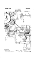
- FIG. 1 is a side elevation of the Wrapping machine having my improvement applied thereto;
- Figure 2 is a plan View partially 1n section 0n the line 2 2 of Figure l;
- Figure 3 is a vertical section on the line 3 3 of Figure 2;
- Figure 4 is a detail of the lever mechanism for the shuttle brake, the view being taken on the line 4 4 of Figure 1.
- the machine comprises a base 1, at one side of which is arranged a support 2 for the operating motor 3, the pinion 4 of which engages a gear 5 which carries a clutch 6, both being rotatable upon the main driving shaft 7.
- the clutch is operated to connect it to the driving shaft by means of a shifting 'lever 8 pivoted to the base of the machine at 9 and connected at its upper end to a lilik 10 which is, in turn ⁇ secured to a control shaft l2 mounted in suitable bearings 13 on the machine frame.
- the forward end of the shaft is provided with a hand lever 14 and, if desired, foot treadles 15 may also be incorporated in the machine, these treadles being connected to a cross bar 16 secured to the shaft 12 at any convenient point.
- adjustable supporting rollers or drums 16 which are concave or flanged as desired, and are intende-d to support and drive the object to be wrapped, herein shown at 17.
- the means for adjusting the rollers to accommodate various sizes of articles need not be described herein, nor will the means for driving one or both of them, as neither of these features form any part of the present invention, it being sulicient merely to state vtrack or raceway 21.
- the shuttle carrier shuttle ' is substantia lyring shaped ,asl
- the shuttlek carries upon its upper surfacea pinor, )spool 25 upon which ytheroll ofgwra p1ng1ma terial 26 is supporte'd,fthefmaterial passing from the s oolover a tension device 27, through a older 28 andover a. 29 to the article.
- the shuttle is'driven from a pulley 30 on the main shaft by a belt 31.
- the belt is guided by a series of pulleys, indicated by the numerals 32, so that it passes 'from the pulley 30 to the top plate of the machlne and then in a horizontal plane around two v sides of the shuttle, being received in a groove 33 in the outer periphery thereof and back.
- an enlargement o r projection 34 which, in this form of the invention and as shown in Figure 2, is in the form of a cam or curved lug which is preferably formed as an eccentric curved surface projecting outwardly. from the outer surface of the shuttle.
- a lever 35 On the upper surface of the top plate 18 is pivoted a lever 35, the free end of which is provided with a brake shoe 36 adapted to contact with the cam 34 and 1s so located so that when the lever is rocked about its pivot toward the shuttle, the latter will be stopped with its gap in line with the gap in the shuttle frame.
- the rear end of the lever is provided with a series of holes 37 for major adjustn'ient purposes, in which is .received one end of an angular pin 38 which is adjustably received in a pivoted fork 39 so that minor adjustments may be made ( Figure 4)
- the fork 39 is pivoted to a small bell crank 40 which is 'in 'turn connected to the upper end of a link 41 which at its lower end 1s pivotally 'connected to a arm 42 carried upon the shaft 12.
- VVhatfis claimed is: y
- a wrapping machine of the character described, the combination of a shuttle frame, a ring shuttle mounted on said frame, the frame and shuttle being provided with openings through which the article may be passed, means includin a clutch to rotate the shuttle, avbrake mec anism adjacent the shuttle, a cam formation on the outer periphery of the shuttle and with which the brake is adapted to engage, and a common operating member to release the clutch and apply the brake to the cam.
- a ring shuttle constructed so as to permit the insertion of an article to be Wrapped therein
- means to rotate the ring shuttle including a clutch and means adapted to stop the rotation of the shuttle at a delinite point comprising a brake, a fixed formation on the shuttle, means to move the brake so that it is in position to engage the formation and a simultaneously operating clutch releasing mechanism.
- a Wrapping machine the combination of a ring shuttle constructed so as to permit the insertion of an article to be wrapped therein, a cam formation on the outer periphery of the shuttle, a pivoted brake adjacent the shuttle, and means to move the brake to engage the cam formation.
Description
Feb. 23 ,1926.
F. M. PIERCE WRAPPING MACHINE 3 ySheets-Skaai'. 1
Filed Jan. 10, 1924 Feb. 23 1926. 1,574,438
F. M. PIERCE WRAPPING MACHINE Filed Jan. 10, 1924 5 Sheets-Shea?I 2 Q ZUZ'NQSS' fkA/vk /7. H5965.
@Cw/f@ d@ Feb. 23 1926. 1,574,438
F. M. PIERCE WRAPPING MACHINE Filed Jan. l0, 1924 5 Sheets-Sheet 3 vPatented Feb. 23, 1926.
UNITED STATES PATENTl GFFICE.
ERANx M. RIERCE, OE CHICAGO, ILLINOIS, AssIeNoR To MERCE WRAPIING MA- CHINE COMPANY, or CHICAGO, ILLINOIS, A CORPORATION 0F ILLIN01S- wRAPrING MACHINE.
Application led January 10, 1924. Serial No. 685,325.
To all 'whom it ma concern:
Be it known that I, FRANK M. PIERCE, a citizen of the United States, and a resident of Chicago, county of Cook, State of Illinois, have invented certain new and useful Im rovements in VVrapp-ing Machines, of which the followin is a specification.
This invention re ates to machines for use in Wrapping annular objectsxsu'ch as automobile tires, coils of wire, or similar articles, with a spirally applied wrapping` such, for example, as a paper Wrapping. The invention relates to machines of the type shown in my prior Patent No. 1,399,939 dated December 13, 1921, and is for an improvement thereon, by means of which the machine therein shown may be operated more rapidly and economically.
The machine shown herein is of the type wherein the article to be wrapped is supported and rotated by positively driven feed rollers within the path of a rapidly revolving ring shuttle which passes through the central opening of the rotating article, the shuttle carrying the paper or other material which is thereby wrapped about the article. This type of machine is generally well known. The shuttle is carried in a shuttle frame and both the shuttle and the frame are provided with openings through which the article may be placed in .position and removed when the wrapping is completed, the openings for this purpose being in' registry. The present invention has for its ob ject the provision of mechanism whereby the shuttle is automatically stopped with its opening or gap in registry with the opening or gap in the shuttle supporting frame This mechanism is in combination with the devices which disengage the rotating parts of the machine from its drive so that the stoppage of the shuttle and the other elements of the machine occur simultaneously.
In the drawings: t Figure 1 is a side elevation of the Wrapping machine having my improvement applied thereto;
Figure 2 is a plan View partially 1n section 0n the line 2 2 of Figure l;
Figure 3 is a vertical section on the line 3 3 of Figure 2; and
Figure 4 is a detail of the lever mechanism for the shuttle brake, the view being taken on the line 4 4 of Figure 1.
It will be understood that the machine herein shown is in its principal operative features similar to that shown in my prior patent above referred to and it is therefore unnecessary to describe the details of the machine except in so far as they relate to the specific improvements to be covered herein.
The machine comprises a base 1, at one side of which is arranged a support 2 for the operating motor 3, the pinion 4 of which engages a gear 5 which carries a clutch 6, both being rotatable upon the main driving shaft 7. The clutch is operated to connect it to the driving shaft by means of a shifting 'lever 8 pivoted to the base of the machine at 9 and connected at its upper end to a lilik 10 which is, in turn` secured to a control shaft l2 mounted in suitable bearings 13 on the machine frame. The forward end of the shaft is provided with a hand lever 14 and, if desired, foot treadles 15 may also be incorporated in the machine, these treadles being connected to a cross bar 16 secured to the shaft 12 at any convenient point. By the operation of the lever let or foot treadles 15, the machine may he stopped or started as desired. p
In the frame of the machine are mounted the adjustable supporting rollers or drums 16, which are concave or flanged as desired, and are intende-d to support and drive the object to be wrapped, herein shown at 17. The means for adjusting the rollers to accommodate various sizes of articles need not be described herein, nor will the means for driving one or both of them, as neither of these features form any part of the present invention, it being sulicient merely to state vtrack or raceway 21. The shuttle carrier shuttle 'is substantia lyring shaped ,asl
shown, bein broken'away to ,permit the insel-tion of t e article, the parts belngpositioned in Figure2 so that the article may be insertedv or removed. The shuttlek carries upon its upper surfacea pinor, )spool 25 upon which ytheroll ofgwra p1ng1ma terial 26 is supporte'd,fthefmaterial passing from the s oolover a tension device 27, through a older 28 andover a. 29 to the article. l u
The shuttle is'driven from a pulley 30 on the main shaft by a belt 31. The belt is guided by a series of pulleys, indicated by the numerals 32, so that it passes 'from the pulley 30 to the top plate of the machlne and then in a horizontal plane around two v sides of the shuttle, being received in a groove 33 in the outer periphery thereof and back.
to the pulley 30. A At one point on the outer periphery of the shuttle is formed an enlargement o r projection 34, which, in this form of the invention and as shown in Figure 2, is in the form of a cam or curved lug which is preferably formed as an eccentric curved surface projecting outwardly. from the outer surface of the shuttle. On the upper surface of the top plate 18 is pivoted a lever 35, the free end of which is provided with a brake shoe 36 adapted to contact with the cam 34 and 1s so located so that when the lever is rocked about its pivot toward the shuttle, the latter will be stopped with its gap in line with the gap in the shuttle frame. The rear end of the lever is provided with a series of holes 37 for major adjustn'ient purposes, in which is .received one end of an angular pin 38 which is adjustably received in a pivoted fork 39 so that minor adjustments may be made (Figure 4) The fork 39 is pivoted to a small bell crank 40 which is 'in 'turn connected to the upper end of a link 41 which at its lower end 1s pivotally 'connected to a arm 42 carried upon the shaft 12.
By the mechanism which has been described, it will be seen that as the shaft 12 is rocked toward the left, as shown in Fig. ure 1, the clutch 6 will be released andthe brake 34 will be brought into position to engage the projection 36 as the shuttle revolves, and the shuttle will be stopped with its parts in position so that the object can be removed. Should the lever be operated just as the cam is passing the brake, it will continue its revolution and be caught and held when these parts are again brought into cooperation.
aimsfto provide a positive stop for the shuttle""vc"ithA the gap or shuttle opening in line with `the. corres ondin gap 1n the shuttle frame., .It may u e use 'in all types of wrappin `,machines oft-his general desi and wit ip open gap shuttles or those whlch are provided with swinging or removable gates. .The action of the attachment is quick and positive and will save time in the operation of the machine.
Changes and modifications other than those suggestedmay be made in the design of the machine within the scope of the claims appended hereto.`
VVhatfis claimed is: y
1. In a wrapping machine of the character described, the combination of a shuttle frame, a ring shuttle mounted on said frame, the frame and shuttle being provided with openings through which the article may be passed, means includin a clutch to rotate the shuttle, avbrake mec anism adjacent the shuttle, a cam formation on the outer periphery of the shuttle and with which the brake is adapted to engage, and a common operating member to release the clutch and apply the brake to the cam.
2. In a lwrapping machine, the combination of a ring shuttle constructed so as to permit the insertion of an article to be Wrapped therein, means to rotate the ring shuttle including a clutch and means adapted to stop the rotation of the shuttle at a delinite point comprising a brake, a fixed formation on the shuttle, means to move the brake so that it is in position to engage the formation and a simultaneously operating clutch releasing mechanism.
3. In a wrapping machine, the combination of a ring shuttle constructed so as to permit the insertion of an article to be wrapped therein, driving mechanism for theJ ring shuttle including means to disconnect it therefrom, a brake, a fixed formation on the shuttle, and means operable to simultaneously apply the brake to engage the formation and disconnect the driving mechamsm. u
4. In a Wrapping machine, the combinat1on of a ring shuttle having a gap therein, a stop formation located on the shuttle at a fixed point spaced from the gap, and a brake lever movable to engage the formation.
5. In a Wrapping machine, the combination of a ring shuttle constructed so as to permit the insertion of an article to be wrapped therein, a cam formation on the outer periphery of the shuttle, a pivoted brake adjacent the shuttle, and means to move the brake to engage the cam formation.
6. In'a wrapping machine, the combina.- '7. In a. wrapping machine, the combination of a ring. shuttle havin a gap theretion of n ringshuttle having an opening in, a shuttle support also aving a lgap -therethrou h, and means to frictionajly eh- 10 therein, .and lmeans yto rictionally engge gage-the 's uttle and acting to bring it 'to 5 the shuttle" and acting to bringl 1t to rest rest with its opening in adenite position.
v with its gap jin registry with the gap :in the v frame. y FRANK M. PIERCE.
Priority Applications (1)
| Application Number | Priority Date | Filing Date | Title |
|---|---|---|---|
| US685325A US1574438A (en) | 1924-01-10 | 1924-01-10 | Wrapping machine |
Applications Claiming Priority (1)
| Application Number | Priority Date | Filing Date | Title |
|---|---|---|---|
| US685325A US1574438A (en) | 1924-01-10 | 1924-01-10 | Wrapping machine |
Publications (1)
| Publication Number | Publication Date |
|---|---|
| US1574438A true US1574438A (en) | 1926-02-23 |
Family
ID=24751697
Family Applications (1)
| Application Number | Title | Priority Date | Filing Date |
|---|---|---|---|
| US685325A Expired - Lifetime US1574438A (en) | 1924-01-10 | 1924-01-10 | Wrapping machine |
Country Status (1)
| Country | Link |
|---|---|
| US (1) | US1574438A (en) |
Cited By (1)
| Publication number | Priority date | Publication date | Assignee | Title |
|---|---|---|---|---|
| EP0033196B1 (en) * | 1980-01-09 | 1984-07-11 | Caterpillar Tractor Co. | Winding apparatus |
-
1924
- 1924-01-10 US US685325A patent/US1574438A/en not_active Expired - Lifetime
Cited By (1)
| Publication number | Priority date | Publication date | Assignee | Title |
|---|---|---|---|---|
| EP0033196B1 (en) * | 1980-01-09 | 1984-07-11 | Caterpillar Tractor Co. | Winding apparatus |
Similar Documents
| Publication | Publication Date | Title |
|---|---|---|
| US1574438A (en) | Wrapping machine | |
| GB882504A (en) | Improvements relating to tyre building machines | |
| US2109739A (en) | Skin, hide and leather working machine | |
| US2277967A (en) | Duplicating machine | |
| US1500984A (en) | Wrapping machine | |
| US2082400A (en) | Web splicing device | |
| GB259632A (en) | Improvements in web winding machines | |
| US2260465A (en) | Duplicating machine | |
| US2063359A (en) | Web splicing device | |
| US2129618A (en) | Web supply mechanism for printing machines | |
| US1304630A (en) | Web-feeding mechanism for printing-machines | |
| US1086401A (en) | Machine for applying transfer-stamps to fabrics. | |
| US1752489A (en) | Wrapping apparatus | |
| US1432034A (en) | Wrapping machine | |
| US1491421A (en) | Bead-closing- mechahism fos tike-wrapping machines | |
| US1443031A (en) | Machine for applying sealing material to can lids | |
| US1176914A (en) | Can-top-cutting machine. | |
| US1512300A (en) | Inking device for marking machines | |
| US1373040A (en) | Yarn-winding machine | |
| US1807651A (en) | Wrapping machine | |
| US594507A (en) | Out wrappees oe binders foe oigaes | |
| US1865650A (en) | Bead closing mechanism for tire wrapping machines | |
| US1106363A (en) | Cutting-machine. | |
| US1841506A (en) | Shuttle mechanism for wrapping machines | |
| US2454758A (en) | Flexible cover forming machine |