US1574425A - Separation of gaseous mixtures by liquefaction and rectification and apparatus therefor - Google Patents
Separation of gaseous mixtures by liquefaction and rectification and apparatus therefor Download PDFInfo
- Publication number
- US1574425A US1574425A US634206A US63420623A US1574425A US 1574425 A US1574425 A US 1574425A US 634206 A US634206 A US 634206A US 63420623 A US63420623 A US 63420623A US 1574425 A US1574425 A US 1574425A
- Authority
- US
- United States
- Prior art keywords
- rectification
- liquefaction
- expansion
- chamber
- piston
- Prior art date
- Legal status (The legal status is an assumption and is not a legal conclusion. Google has not performed a legal analysis and makes no representation as to the accuracy of the status listed.)
- Expired - Lifetime
Links
Images


Classifications
-
- F—MECHANICAL ENGINEERING; LIGHTING; HEATING; WEAPONS; BLASTING
- F25—REFRIGERATION OR COOLING; COMBINED HEATING AND REFRIGERATION SYSTEMS; HEAT PUMP SYSTEMS; MANUFACTURE OR STORAGE OF ICE; LIQUEFACTION SOLIDIFICATION OF GASES
- F25J—LIQUEFACTION, SOLIDIFICATION OR SEPARATION OF GASES OR GASEOUS OR LIQUEFIED GASEOUS MIXTURES BY PRESSURE AND COLD TREATMENT OR BY BRINGING THEM INTO THE SUPERCRITICAL STATE
- F25J3/00—Processes or apparatus for separating the constituents of gaseous or liquefied gaseous mixtures involving the use of liquefaction or solidification
- F25J3/02—Processes or apparatus for separating the constituents of gaseous or liquefied gaseous mixtures involving the use of liquefaction or solidification by rectification, i.e. by continuous interchange of heat and material between a vapour stream and a liquid stream
- F25J3/04—Processes or apparatus for separating the constituents of gaseous or liquefied gaseous mixtures involving the use of liquefaction or solidification by rectification, i.e. by continuous interchange of heat and material between a vapour stream and a liquid stream for air
Definitions
- This invention relates to refrigeration as applied to theliquefaction of gaseous mixtures, and the separation of the constituents of such mixtures.
- the improvements which are the object of the present invention permit of increasing this yield for the separation of a gaseous mixture into its constituents by 1i uefact on ,and rectification, a great part 0 .the cold produced by the expansion being no longer carried away by the gas leaving the expane sion chamber, but utilized on the spot in the mixture.
- a vertical expansion cylinder may be 3' ac eted to permit circulation of the gaseous mixture in an upward direction.
- the cylinder should be sufficiently long in proportion to its diameter, and it would be ofadvantage to increase the pansion chamber with which the expanding .90 surfaces along which condensation takes 1 place by disposing along'thepath of the gaseous mixture between the 'two. walls gas is in contact.
- any other rectificationdevice could be. employed, as for instance, superposed dephlegmatori plates of the bubbling type, constituting: thus a sort of annular distillation column in the center of which is the expansion chamber or cylinder in which the piston operates.
- the reciprocating expansion engines in which, for the purpose of refrigeration, a gas is expanded with external work, are, taken as a whole, similar to compressed air motors, i. e., a piston .rod, through the intermediary of a connecting rod and a crank, actuates a shaft carrying a flywheel and a pulley, by means of which the power is transmitted to a machine for utilizing this power or acting merely as a brake for the motor by converting the power into heat which is diss pated into the surrounding atmosphere as in the case of a dynamometer.
- the delivery otthe gas to be expanded into the cylinder is likewise effected by the customary mechanisms provided for this purpose in compressed-air motors, viz, by means of slide or poppet valves mechanically actuated by devices such as eccentrics, cams and rods, set in motion by the motor itself.
- slide or poppet valves mechanically actuated by devices such as eccentrics, cams and rods, set in motion by the motor itself.
- the expansion cylinder may be placed under the same insulating jacket as the rest of the apparatus by giving to the piston rod a suflicient length to make its further end extend beyond the jacket whereby it is possible to place the mechanism to be actuated by this rod and the frame supporting this mechanism outside the insulating jacket.
- This arrangement has the advantage of avoiding direct contact between the very cold expansion cylinder and metallic masses of rather considerable size as compared with that of the cylinder, thus avoiding losses by conduction.-
- the gas distributor delivering gas into the eylinder be placed very close to the lat- -ter, and, it follows that the control of this distributor by means of moving devices exterior to the cylinder and the valve chests and hence located within the insulating jacket itself, is not practical.
- this mechanism consisting in efiectingthe displacement of the movable distributor by applying thereto, within the enclosing valve chest, an impulse applied at the appropriate instant, by one of the moving parts of the expander.
- the transmission of this impulse to the distributor may be either pneumatic, electric or magnetic, without any movable actuating mechanism.
- these various modes of transmitting force could be combined together.
- Fig. 1 is a diagram indicating a simple form of the invention
- Figs. 2 to 6 are similar views indicating the'operation of the valve mechanism
- Fig. 7 is a diagram indicating another mode of applying the invention.
- Fig. 8 is a section on the line 8-8 of Fig. 7;
- Figs. 9 to 12 are similarviews showing another application of the invention.
- Figs. 13 and 14 are diagrams showing how the invention is combined with apparatus for liquefying gaseous mixtures and separating the constituents thereof.
- Fig. 1 which is a vertical section, shows a single-effect expansion cylinder A provided with two walls B and C between which the gaseous mixture circulates from below upward, while it is subjected to a process of partial liquefaction and simultaneous rectification.
- This mixture enters at D after having already been cooled by its passage through a heat exchanger and leaves at E.
- R1ngs F operate in the manner of rectifylng plates on which the liquids formed by partial condensation of the gaseous mixture collect.
- These liquids, descending by gravity, are traversed by the ascending gaseous mixture so that, in proportion to their rate of reflux, they become enriched in the most readily condensable constituent and drain back to the bottom in the form of a liquid enriched in that constituent which leaves the apparatus at G.
- the downward stroke of the piston is by gravity assisted, for example, by the action of a fly-wheel (not shown).
- the entire structure is heavily lagged with a heat-insulating composition.
- Figs. 2, 3, 4, 5 and 6 represent various sponds to the extremity of the screw 1).
- the whole arrangement comprising the'recess o coacting with the screw '0, acts inthe manner of a. buffer applied to the piston-valve M, the movements of which towards the left are more or less retarded by the degree of compression of the air contained in the recess 0, the degree of compression depending upon the amount the extremity g of: the screw :extends into this recess, and hence being regulated from the exterior by turning the screw 'v in the right direction.
- Small auxiliary piston-valve t and 't' are displaced by the piston H. at theend of its downward and upward stroke respectively and returned to their original position by springs r and 1".
- connections between the chest of'the distributor M and those of the small, pistonvalves t and t as well as between-the latter and the compressed air supply pipe I and the expanded air exhaust pipe K, are made by means of tubing.
- a vent is arranged at the point i of the pipe connection.
- the effective area of the vent may be variedbv adjusting the position of the screw R. therebv regulating the speed of displacement of the piston- 'valve M towards the right.
- Figs. 7 and 8 represent (an example of pneumatic control of the distribution for double-efi'eet expansion.
- The" piston H is provided with two annular grooves m and 11 which, by establishing communication at the appropriate moments between conduits opening into the cylinder A, determine the displacement of the piston-valves M which latter, by its successlve positions, controls the distribution.
- a hollow sleeve V is slidingly but loosely auxiliary slide-valve which periodically opens alateral opening W at the upper part of this support.
- This auxiliary slide-valve V slides freely in a recess Z of-the pistonvalve M, with an amount of vertical play which, however, is less than the travel of the valve M so that the latter, after having accomplished part of its upward stroke corresponding to this play, carries the auxiliary slide valve V with it, and the latter, after having been displaced along the support a, uncovers the opening W.
- the valve M having traveled the same distance in its downward course, actuates the auxiliary slide valve. V and closes the opening W.
- Figs. 9, 10, 11 and 12 illustrate an electrically controlled distributing mechanism as applied-to a single-efi'ect expansion cylinder.
- the cylinder. L in which move's'the pistonvalve M, is made of anon-magnetic metal
- the piston-valve M is made of soft iron and forms the plunger of the ceases when the piston. rises, and another contact, sending the current into the solenoid sgis established when the piston H pansionoughttobegin.
- the valve M be: cause of the effect of the solenoid 8,, as-
- the apparatus for establishing the contacts may be given various forms.
- Figs. 9 to 12 where m and m are the conductors connected to the source of electricity, the mechanisms for establishing contact at the extreme ends of the piston stroke, consist of small spring-controlled contact studs t and t against which the piston H strikes.
- the expansion contact is controlled by a small articulated lever L which is returned to its'middle osition by springs 1', 1*, after the piston rodj provided for this purpose with an abutment b, has lifted it to make electric contact at cl. No contact is made during the return of the piston rod, as there should be contact only during the upward stroke. All these elements, comprising the lever Z, its springs 1',
- Fig. 12 shows in detail how the electric circuit is closed when one of the studs t or t (t, for instance), is pushed inwardly by the piston H upon its arrival at the bottom of its stroke; the conducting and in sulated. piece 29 is thus made to bear against two conducting branches 0 and 0 connected to the electric circuit, It is understood, of course. that all of the parts are properly insulated.
- the solenoids may be located inside the distribution chest, particularly when, owing to the increase in pressure, it is desirable to provide such a wall thickness for the chest as to render the outer coils wound thereon impracticable on account of the large air-gap.
- the solenoids may also be easily combined so as to bring about distribution in the caseof a double-effect expansion engine.
- the compressed air after a preliminary cooling by heat. exchange with the gases leaving after separation, goes partly into the interior of the, expansion chamber and partly into the liquefaction andrectification chamber surrounding the expansion chamber.
- the partially expanded air in the expansion chamber is sent into the interior of another chamber bathed externally by the liquid coming from a rectification column. It is there partly or totally liquefied, thereby causing the simultaneous vaporization of the external liquid.
- the products of these various condensations are discharged into the rectification column at heights corresponding with their respective compositions. 1
- Fig. 13 shows an apparatus for carrying this improved process into practice.
- the compressed air arriving at L passes through heat-exchangers T T goes through the tube I into the expansion cylinder while another part passes through the tube D into the space between the two walls B and O, which space. fitted withcolumn plates, forms the liquefaction and rectification chamber.
- the expansion Part of the air cylinder with'its double wall and the column plates is in its other parts, constructed as has been explained for Fig. 1.
- the distributing mechanism is controlled by one of the mechanisms described above.
- the partly expanded gas leaving the cylinder A by the pipe K passes into a rectifying column N and a vaporizer liquefier Q surrounded externally by the liquid refluxed from the column.
- the gas forming the residue from the partial liquefaction and rectification is liquefied in a coil J immersed in liquid in the column before being introduced therein.
- the figure clearly shows the various circuits carried out by the air, the liquid and the separated gases, respectively.
- the compressed air previously cooled by heat exchange may, if desired, also be sent in its entirety intothe liquefaction and rectification jacket. In that case, however, the gaseous residue from these operations, after partial expansion for the production of cold, is delivered, as described above, to the liquefaction vaporization chamber, and into the rectification column.
- Fig. 14. represents an apparatus for carrying out the above-described process in connection with the liquefaction of oxygen.
- the same reference characters refer to the same parts as in Fig. 13.
- the residual gas leaving at E after partial liquefaction and, rectification of the compressed air, all of which is'supplied through tube D passes through I into the expansion chamber, leaving the latter through pipe K which ment of the parts without departing from the invention or sacrificing any-of the advantages thereof.
- the method of separating the constituents of gaseous mixtures by liquefaction and rectification which comprises liquefying and simultaneously rectifying the gaseous mixture by the refrigerative effect of a gas, which is expanding with external work, in a chamber in heat transfer relation with the chamber in which the expansion occurs.
- The-method of separating the constituents of gaseous mixtures by liquefaction and rectification which comprises causing the gaseous mixture to travel upwardly while it is subjected for liquefaction and simultaneous rectification to the refrigerative effect of a gas, which is expanding with external work, in a chamber in heat transfer relation with the chamber in which the expansion occurs.
- the method of separating the constituents of aseous mixtures by liquefaction and rectification which comprises causing the gaseous mixture to travel upwardly while it is subjected. for liquefaction and simultaneous rectification to the refrigerative effect of a gas, which is expanding with external work 1n a chamber in heat transfer relation with the chamber in which the expansion occurs, Withdrawing the residual' unliquefied as from the to of theliquefaction cham er and the liquld from the bottom thereof.
- the method of separating the constituents of gaseous mixtures by liquefaction and rectification which comprises causing the gaseous mixture to travel upwardly while it is subjected for liquefaction and simultaneous rectification to the refrigerative effect of a gas, which is expanding with external work, in a chamber in heat transfer relation with the chamber in which the expansion occurs, withdrawing the residual unliquefied gas from the top of the liquefaction chamber and the liquid from the bottom thereof, and expandin the residualunliquefied gas to produce t e refrigerative efiect.
- the method of separating the constituents of gaseous mixtures by liquefaction and simultaneous rectification which comprises subjecting the gaseous mixture to the refrigerative effect of a gas, which is expandlng with external work, in a chamber in heat transfer relation with the chamber in which the expansion occurs, withdrawing the liquid and the residual unliquefied gas and subjecting them to a rectification.
- the method of separating the constituents of gaseous mixtures by liquefaction gas and so and simultaneous rectification which comprises subjecting the gaseous mixture to the 'refrigerative effect of a gas, which is expanding with external work, in a cham: ber-in heat transfer relation with the chamber in which the expansion occurs, withdrawing the liquid and the residual unliquefied gas, li uefyin'g the residual unliquefied jecting both liquidsto a rectification.
- the method of separating the constituents of gaseous mixtures by liquefaction and rectification which comprises causing 'and rectification, which comprises causing the gaseous mixture to travel upwardly while it is subjected for liquefaction and.
- the method of separating the constitwants of gaseous mixtures by liquefaction and rectification which comprises compressing and eoolin the gaseous mixture, causing a portion t ereof to expand with external work, subjecting the remainder of the gaseous mixture for liquefaction and simultaneous rectification to the refrigera tive effect of the expanding mixture in a chamber in heat transfer relation with the chamber in which expansion occurs and subjecting the products of'the liquefaction thus accomplished to rectification.
- the method of separating the constituents of gaseous mixtures by liquefaction and rectification which comprises compressing and cooling the gaseous mixture, subjeeting it for liquefaction and simultaneous rectification to the rcfrigerative effect of a gas, which is expanding with external work, in a chamber in heat transfer relation with the chamber in which the expansion occurs, expanding the unliquefied residual gas to produce the refrigerative effect, liquefying the expandedresidual gas and subjecting it with the liquid produced by refrigeration of the gaseous. mixture before expansion to rectification.
- the method of separating the constituents of gaseous mixtures by liquefaction and rectifieation which comprises compressing and cooling the gaseous mixture, caus ing a portion thereof to expand with external work, subjecting the remainder of the gaseous mixture for liquefaction and simultaneous rectification to the refrigerative effect of the expanding mixture in a. chamber inheat transfer relation with the chamb r inwhich expansion occurs and subjecting the products of the liquefaction thus accomplished to rectification after liquefaction of the expanded gaseous mixture.
- an apparatus for separating the constituents of gaseous'mixtures the combination of an expansion chamber, a jacket therefor, means for introducing a gaseous mixture to the jacket, means for withdrawing a liquid therefrom and means in the jacket to ensure intimate contact between liquid formed and decending therein and the gaseous mixture rising therethrough.
- an expansion chamber in an apparatus for separating the constituents of gaseous mixtures, the combination of an expansion chamber, a jacket therefor, means f or introducing the gaseous mixture to the jacket, means for withdrawing a liquid therefrom, means in the jacket to ensure intimate contact between liquid formed and descending therein and the gaseous mixture rising therethrough, a mov able piston in the expansion chamber and remote control means actuated by the movement of the piston to ensure the introduction and withdrawal of fluid to and from the expansion chamber at appropriate intervals.
Description
Feb. 23 1926. 1,574,425
E. JORDAN SEPARATION OF GASEOUS MIXTURES BY LIQUEFACTION AND RECTIFICATION AND APPARATUS THEREFOR Filed April 24, 1923 6 Sheets-Sheet 1 IN VEN TOR J ATTORNEY Feb. 23 1926-. 1,574,425
' E. DAN SEPARATION OF GASEOUS MIXTURES BY LIQUEFACTION AND RECTIFICATION AND APPARATUS THEREFOR Filed April 2 1923 6 Sheets-Sheet 2 A TTORNE Y Feb.'23 1926. 1,574,425
E. JORDAN SEPARATION OF GASEOUS MIXTURES BY LIQUEFACTION AND RECTIFiCATION AND APPARATUS THEREFOR Filed April 24, 1923 6 Sheets-Sheet. 4
a INVENTOR ATTORNEY Feb 23 1926. 1,574,425
E. JORDAN SEPARATION OF GASEOUS MIXTURES BY LIQUEFACTION AND RECTIFICATION ANDAPPARATUS THEREFOR Filed April 24, 1923 6 Sheets-Sheet 5 Illll II'IIIIILIIIIIL':
, INVENTOR MMQ 24.0w
ATTORNEY "Feb; 23 1 2e.- 1,574,425
. R AN SEPARATION OF GASEOUS MIXTURES BY LIQUEFACTION AND RECTIFICATION AND APPARATUS THEREFOR v Filed April 24,. 1923 6 Sheets-Sheet 6 INVENTOR A TTORNE Y nuemm 303mm, o r'rmrs, Imam, assreuon. r 'socm'rn um LIQUIDE (socm'm nnomn POUR LET-UDE ET rnnxrnorre rron mas PROCEDES cnonens camps),
on runs, rmcn.
- snrsaa'rrou or ensnous urx'runns' BY Lmunrnc'rron um nnc'rmcn'rronamn nrrm'rusrnnmoa. j
Application and Apr1l24, 192s. seriai'no. 634.206,.
To all whom it my concern:
Be it known that I, EUGENE JORDAN, a'
citizen of the Republic of France, residing at Paris, Republicof France, have invented certain new and useful Improvements 1n Separation of Gaseous Mixtures by Liquefaction and Rectification and Apparatus-Therefor'; and I do hereby declare the following to be a full, clear, and exact description ofthe invention, such as will enable others skilled in the art to which it appertains to make and use the same.
This invention relates to refrigeration as applied to theliquefaction of gaseous mixtures, and the separation of the constituents of such mixtures. j
I In the use of refrigeration to separatea gaseous mixture into its elements by, liquefaction and rectification where the cold isobtainedby the expansion of a gas producing external work, it is the usual practice to use the gas, leaving the chamber in which it expands, as a carrier for the cold resulting from-expansion and to avoid. a loss across the wall of this chamber by insulating this wall externally. After its expansion the gas is delivered to theli uefaction and rectification a paratus, .of w ich the heat insulation is in ependent"of that ofthe ex ansion chamber which is separated from t at 3P? paratus.
With this procedure, we do not obtain the best yield of cold produced by the expansion by reason of the inevitable losses of cold during the transportation thereof from the expansion chamber where it is produced to the points in the apparatus where it is utilized. There are also some losses during the travel between the apparatus and the expansion chamber, by the gas which is caused to expand after a preliminary cooling byheat exchange. v
The improvements which are the object of the present invention permit of increasing this yield for the separation of a gaseous mixture into its constituents by 1i uefact on ,and rectification, a great part 0 .the cold produced by the expansion being no longer carried away by the gas leaving the expane sion chamber, but utilized on the spot in the mixture.
'manner hereinafter described. "The travel then of the :expanded gas, as well as the travel of the already cold gas which isabout to expand between the apparatus and the expansion chamber, is considerably reduced. 0 According to the method, the gaseous mixture, the constituents of which are to be separated, .is partially liquefied by means to rectlfication. These chambers can, more over, be uxtaposed to the remainder of the apparatus proper under the same insulation.
Eventually, particularly for, the separation of .air intoits constituent elements, the as which expands could be the gaseous resi ue from the partial liquefaction obtained as described above. 4
For conducting the operation, suitable apparatus may be employed. For exam le, a vertical expansion cylinder may be 3' ac eted to permit circulation of the gaseous mixture in an upward direction. Thus, partial lique-' 8;
faction isefiected by "the cold transmitted across the wall of the expansionchamber. while at the same time there is a rectification of the condensed liquid which, descend- "ing by gravity, circulates in a reverse direction to the direction of travel of the gaseous In order to increase the useful effect of this rectification, the cylinder should be sufficiently long in proportion to its diameter, and it would be ofadvantage to increase the pansion chamber with which the expanding .90 surfaces along which condensation takes 1 place by disposing along'thepath of the gaseous mixture between the 'two. walls gas is in contact. Moreover, any other rectificationdevice could be. employed, as for instance, superposed dephlegmatori plates of the bubbling type, constituting: thus a sort of annular distillation column in the center of which is the expansion chamber or cylinder in which the piston operates.
As indicated, it is desirable to locate the expansion cylinder as close as possible to the rest of the apparatus within a common insulating jacket. Heretofore the reciprocating expansion engines in which, for the purpose of refrigeration, a gas is expanded with external work, are, taken as a whole, similar to compressed air motors, i. e., a piston .rod, through the intermediary of a connecting rod and a crank, actuates a shaft carrying a flywheel and a pulley, by means of which the power is transmitted to a machine for utilizing this power or acting merely as a brake for the motor by converting the power into heat which is diss pated into the surrounding atmosphere as in the case of a dynamometer. The delivery otthe gas to be expanded into the cylinder is likewise effected by the customary mechanisms provided for this purpose in compressed-air motors, viz, by means of slide or poppet valves mechanically actuated by devices such as eccentrics, cams and rods, set in motion by the motor itself. There is thus between the piston and the distributing mechanism proper (slide or poppet valves), a mechanical connection accomplished by means of movable parts arranged externally to the cylinder and the valve-box.
The expansion cylinder may be placed under the same insulating jacket as the rest of the apparatus by giving to the piston rod a suflicient length to make its further end extend beyond the jacket whereby it is possible to place the mechanism to be actuated by this rod and the frame supporting this mechanism outside the insulating jacket. This arrangement has the advantage of avoiding direct contact between the very cold expansion cylinder and metallic masses of rather considerable size as compared with that of the cylinder, thus avoiding losses by conduction.- However, it is necessary that the gas distributor delivering gas into the eylinder be placed very close to the lat- -ter, and, it follows that the control of this distributor by means of moving devices exterior to the cylinder and the valve chests and hence located within the insulating jacket itself, is not practical.
By means of a mechanism peculiar to the present invention these moving parts are avoided, the essential purpose of this mechanism consisting in efiectingthe displacement of the movable distributor by applying thereto, within the enclosing valve chest, an impulse applied at the appropriate instant, by one of the moving parts of the expander. The transmission of this impulse to the distributor may be either pneumatic, electric or magnetic, without any movable actuating mechanism. Moreover, these various modes of transmitting force could be combined together.
The annexed drawings represent diagrammatically various modes of practical embodiment of the apparatus described above. In the drawings,
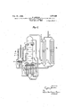
Fig. 1 is a diagram indicating a simple form of the invention;
Figs. 2 to 6 are similar views indicating the'operation of the valve mechanism;
Fig. 7 is a diagram indicating another mode of applying the invention;
Fig. 8 is a section on the line 8-8 of Fig. 7;
Figs. 9 to 12 are similarviews showing another application of the invention; and
Figs. 13 and 14 are diagrams showing how the invention is combined with apparatus for liquefying gaseous mixtures and separating the constituents thereof.
Fig. 1, which is a vertical section, shows a single-effect expansion cylinder A provided with two walls B and C between which the gaseous mixture circulates from below upward, while it is subjected to a process of partial liquefaction and simultaneous rectification. This mixture enters at D after having already been cooled by its passage through a heat exchanger and leaves at E. R1ngs F operate in the manner of rectifylng plates on which the liquids formed by partial condensation of the gaseous mixture collect. These liquids, descending by gravity, are traversed by the ascending gaseous mixture so that, in proportion to their rate of reflux, they become enriched in the most readily condensable constituent and drain back to the bottom in the form of a liquid enriched in that constituent which leaves the apparatus at G.
The gas, which is expanded in the cylinder and which acts by its pressure on the piston H during the upward stroke of the latter,
enters under pressure through the inlet port I, after the preliminary cooling there of by heat exchange, and leaves after expansion through the outlet port K. The
distributor M controls the admission, the
degree of expansion and the exhaust. The downward stroke of the piston is by gravity assisted, for example, by the action of a fly-wheel (not shown). The entire structure is heavily lagged with a heat-insulating composition.
Figs. 2, 3, 4, 5 and 6 represent various sponds to the extremity of the screw 1). The whole arrangement, comprising the'recess o coacting with the screw '0, acts inthe manner of a. buffer applied to the piston-valve M, the movements of which towards the left are more or less retarded by the degree of compression of the air contained in the recess 0, the degree of compression depending upon the amount the extremity g of: the screw :extends into this recess, and hence being regulated from the exterior by turning the screw 'v in the right direction. Small auxiliary piston-valve t and 't' are displaced by the piston H. at theend of its downward and upward stroke respectively and returned to their original position by springs r and 1".
Connections between the chest of'the distributor M and those of the small, pistonvalves t and t as well as between-the latter and the compressed air supply pipe I and the expanded air exhaust pipe K, are made by means of tubing. A vent is arranged at the point i of the pipe connection. The effective area of the vent may be variedbv adjusting the position of the screw R. therebv regulating the speed of displacement of the piston- 'valve M towards the right.
Aswill be readily seen by reference to the Fig. '2, the displacements of the small piston valves t and t by the piston H, upon arriving at the extremeends of its stroke, .cause the piston-valve M through the intermediary of the compressed air to occupy 'alternately the positions shown inFig l '(air admission phase and upward stroke of piston H) and Fig5 (expansion to the end of the upward stroke-of piston H) followed by its return to the position shown in Fig. 2 (exhaust phase and downward stroke of piston -H). Figs. 3 and 6 show the respective positions of he auxiliary pistomvalves t and t when t piston H arrives at the ex treme ends of its stroke. It will'be seen that thelength of the intake period may be' determined at will by regulating the'posi tion of the screws V and R or of the latter alone.
Figs. 7 and 8 represent (an example of pneumatic control of the distribution for double-efi'eet expansion. .The" piston H is provided with two annular grooves m and 11 which, by establishing communication at the appropriate moments between conduits opening into the cylinder A, determine the displacement of the piston-valves M which latter, by its successlve positions, controls the distribution. The screw V as well as thecontrol screw R of an air vent, as at-carry out in this case the same functions as in Fig.2. 7 1
A hollow sleeve V is slidingly but loosely auxiliary slide-valve which periodically opens alateral opening W at the upper part of this support. This auxiliary slide-valve V slides freely in a recess Z of-the pistonvalve M, with an amount of vertical play which, however, is less than the travel of the valve M so that the latter, after having accomplished part of its upward stroke corresponding to this play, carries the auxiliary slide valve V with it, and the latter, after having been displaced along the support a, uncovers the opening W. Upon the return stroke the valve M, having traveled the same distance in its downward course, actuates the auxiliary slide valve. V and closes the opening W.
By examining the figure, the manner of operation will be readily understood. The auxiliary valve V opening and closing the orifice W at suitable periods, the rapid closure of the inlet port, owing to the groove 9 of the piston valve M which, at the desired moment establishes communication'between the pipe c and the pipes e andh respectively, connected to the'exha'ust port K. This communication, by bringing about the rapid blowing 'ofi of part of the air contained in the space '9, causes momentarily and during the time necessary for the closure'of the admission ports, a-greater speed of the piston-valve M during its downward stroke.
Figs. 9, 10, 11 and 12 illustrate an electrically controlled distributing mechanism as applied-to a single-efi'ect expansion cylinder.
The cylinder. L in which move's'the pistonvalve M, is made of anon-magnetic metal,
e. g., bronze. The piston-valve M is made of soft iron and forms the plunger of the ceases when the piston. rises, and another contact, sending the current into the solenoid sgis established when the piston H pansionoughttobegin. The valve M, be: cause of the effect of the solenoid 8,, as-
reaches the,, point of'its course at "which ex-,
sumes the position of FigQlO in which the 4 admission port is shown to be closed. This second contact ends when the piston HJcontinues its travel and a new contact, sending the current intothe solenoid S is established when the piston H arrives at the top of its stroke so-that under the action ofsolenoid S the .slide valve takes the, position of Fig. .11 in which: theexhaust' port is I open and the piston begins, its downward At thelo'wer end ofits stroke the piston H reestablishes the'first contact as. I mounted on a tubular support u forming anstroke.
above described, and the same cycle recommences. By means of a sliding contact bridge whereby the solenoid S, is energized and, hence, the admission port is closed, the degree of expansion can be varied at will.
The apparatus for establishing the contacts may be given various forms. In Figs. 9 to 12, for instance, 'where m and m are the conductors connected to the source of electricity, the mechanisms for establishing contact at the extreme ends of the piston stroke, consist of small spring-controlled contact studs t and t against which the piston H strikes. The expansion contact is controlled by a small articulated lever L which is returned to its'middle osition by springs 1', 1*, after the piston rodj provided for this purpose with an abutment b, has lifted it to make electric contact at cl. No contact is made during the return of the piston rod, as there should be contact only during the upward stroke. All these elements, comprising the lever Z, its springs 1',
and 1",, and the contact piece (1, are mountedon a bracket a which can be shifted paral lel to the axis of the cylinder by means of the screw S, whereby one may vary at will the moment when contact is made at d and, hence, the moment when the expansion starts. Fig. 12 shows in detail how the electric circuit is closed when one of the studs t or t (t, for instance), is pushed inwardly by the piston H upon its arrival at the bottom of its stroke; the conducting and in sulated. piece 29 is thus made to bear against two conducting branches 0 and 0 connected to the electric circuit, It is understood, of course. that all of the parts are properly insulated.
If desired, the solenoids may be located inside the distribution chest, particularly when, owing to the increase in pressure, it is desirable to provide such a wall thickness for the chest as to render the outer coils wound thereon impracticable on account of the large air-gap. The solenoids may also be easily combined so as to bring about distribution in the caseof a double-effect expansion engine. I
It will be noticed that in all these distribution mechanisms, one and the same element, i. e., the piston-valve, alternately opens and closes the admission and exhaust port, so that in no case can these two parts be opened orclosed simultaneously. This arrangement entails a considerable advantage over the distribution mechanisms in which distinct closing elements which may be simultaneously opened and closed are employed. In the latter case. accidents are liable to occur.
When applying the improvements forming the subject matter of the present application, for instance, to the separation of air into its elements by liquefaction and rectification, with production of cold by means of the expansion of compressed air effecting external work, an improved method results.
, In this method the compressed air, after a preliminary cooling by heat. exchange with the gases leaving after separation, goes partly into the interior of the, expansion chamber and partly into the liquefaction andrectification chamber surrounding the expansion chamber. The partially expanded air in the expansion chamber is sent into the interior of another chamber bathed externally by the liquid coming from a rectification column. It is there partly or totally liquefied, thereby causing the simultaneous vaporization of the external liquid. The products of these various condensations are discharged into the rectification column at heights corresponding with their respective compositions. 1
Fig. 13 shows an apparatus for carrying this improved process into practice. The compressed air arriving at L passes through heat-exchangers T T goes through the tube I into the expansion cylinder while another part passes through the tube D into the space between the two walls B and O, which space. fitted withcolumn plates, forms the liquefaction and rectification chamber. The expansion Part of the air cylinder with'its double wall and the column plates is in its other parts, constructed as has been explained for Fig. 1. The distributing mechanism is controlled by one of the mechanisms described above. The partly expanded gas leaving the cylinder A by the pipe K passes into a rectifying column N and a vaporizer liquefier Q surrounded externally by the liquid refluxed from the column. The gas forming the residue from the partial liquefaction and rectification is liquefied in a coil J immersed in liquid in the column before being introduced therein. The figure clearly shows the various circuits carried out by the air, the liquid and the separated gases, respectively. y
The compressed air, previously cooled by heat exchange may, if desired, also be sent in its entirety intothe liquefaction and rectification jacket. In that case, however, the gaseous residue from these operations, after partial expansion for the production of cold, is delivered, as described above, to the liquefaction vaporization chamber, and into the rectification column.
Fig. 14. represents an apparatus for carrying out the above-described process in connection with the liquefaction of oxygen. The same reference characters refer to the same parts as in Fig. 13. In this case the residual gas leaving at E after partial liquefaction and, rectification of the compressed air, all of which is'supplied through tube D, passes through I into the expansion chamber, leaving the latter through pipe K which ment of the parts without departing from the invention or sacrificing any-of the advantages thereof. I claim 1. The method of separating the constituents of gaseous mixtures by liquefaction and rectification, which comprises liquefying and simultaneously rectifying the gaseous mixture by the refrigerative effect of a gas, which is expanding with external work, in a chamber in heat transfer relation with the chamber in which the expansion occurs.
2. The-method of separating the constituents of gaseous mixtures by liquefaction and rectification, which comprises causing the gaseous mixture to travel upwardly while it is subjected for liquefaction and simultaneous rectification to the refrigerative effect of a gas, which is expanding with external work, in a chamber in heat transfer relation with the chamber in which the expansion occurs.
3. The method of separating the constituents of aseous mixtures by liquefaction and rectification, which comprises causing the gaseous mixture to travel upwardly while it is subjected. for liquefaction and simultaneous rectification to the refrigerative effect of a gas, which is expanding with external work 1n a chamber in heat transfer relation with the chamber in which the expansion occurs, Withdrawing the residual' unliquefied as from the to of theliquefaction cham er and the liquld from the bottom thereof.
4. The method of separating the constituents of gaseous mixtures by liquefaction and rectification, which comprises causing the gaseous mixture to travel upwardly while it is subjected for liquefaction and simultaneous rectification to the refrigerative effect of a gas, which is expanding with external work, in a chamber in heat transfer relation with the chamber in which the expansion occurs, withdrawing the residual unliquefied gas from the top of the liquefaction chamber and the liquid from the bottom thereof, and expandin the residualunliquefied gas to produce t e refrigerative efiect.
5. The method of separating the constituents of gaseous mixtures by liquefaction and simultaneous rectification, which comprises subjecting the gaseous mixture to the refrigerative effect of a gas, which is expandlng with external work, in a chamber in heat transfer relation with the chamber in which the expansion occurs, withdrawing the liquid and the residual unliquefied gas and subjecting them to a rectification.
6. The method of separating the constituents of gaseous mixtures by liquefaction gas and so and simultaneous rectification, which comprises subjecting the gaseous mixture to the 'refrigerative effect of a gas, which is expanding with external work, in a cham: ber-in heat transfer relation with the chamber in which the expansion occurs, withdrawing the liquid and the residual unliquefied gas, li uefyin'g the residual unliquefied jecting both liquidsto a rectification.
7 The method of separating the constit uents 'of gaseous mixtures by liquefaction and rectification, which comprises causing the gaseous mixture to travel upwardly while it is subjected for liquefaction and simultaneous rectification to the refrigerative effect of a gas, which is expanding with external work, in a chamber in heat transfer relation with the chamber in which the expansion occurs,.withdrawing the residual unliquefied gas from the top of the liquefaction cliamber and the liquid from the bottom thereof and subjecting them to fur ther rectification.
8. The method of separating the constituents of gaseous mixtures by liquefaction liquefied gas and subjecting both liquids to.
further rectification.
9, The method of separating the constituents of gaseous mixtures by liquefaction and rectification, which comprises causing 'and rectification, which comprises causing the gaseous mixture to travel upwardly while it is subjected for liquefaction and.
simultaneous rectification to the refrigerative effect of a gas, which is expanding with external work, in a chamber in heat transfer relation with the chamber in which the expansion occurs, withdrawing the residual unliquefied gas from the top of the liquefaction chamber and the liquid from the bottom thereof, expanding the residual unliquefied gas to produce the refrigerative effect, liquefying the expanded residual gas and subjecting both liquids to further rectification.
10. The method of separating the constitwants of gaseous mixtures by liquefaction and rectification, which comprises compressing and eoolin the gaseous mixture, causing a portion t ereof to expand with external work, subjecting the remainder of the gaseous mixture for liquefaction and simultaneous rectification to the refrigera tive effect of the expanding mixture in a chamber in heat transfer relation with the chamber in which expansion occurs and subjecting the products of'the liquefaction thus accomplished to rectification.
11. The method of separating the constituents of gaseous mixtures by liquefaction and rectification, which comprises compressing and cooling the gaseous mixture, subjeeting it for liquefaction and simultaneous rectification to the rcfrigerative effect of a gas, which is expanding with external work, in a chamber in heat transfer relation with the chamber in which the expansion occurs, expanding the unliquefied residual gas to produce the refrigerative effect, liquefying the expandedresidual gas and subjecting it with the liquid produced by refrigeration of the gaseous. mixture before expansion to rectification.
12. The method of separating the constituents of gaseous mixtures by liquefaction and rectifieation,'which comprises compressing and cooling the gaseous mixture, caus ing a portion thereof to expand with external work, subjecting the remainder of the gaseous mixture for liquefaction and simultaneous rectification to the refrigerative effect of the expanding mixture in a. chamber inheat transfer relation with the chamb r inwhich expansion occurs and subjecting the products of the liquefaction thus accomplished to rectification after liquefaction of the expanded gaseous mixture.
13. In an apparatus for separating the constituents of gaseous'mixtures, the combination of an expansion chamber, a jacket therefor, means for introducing a gaseous mixture to the jacket, means for withdrawing a liquid therefrom and means in the jacket to ensure intimate contact between liquid formed and decending therein and the gaseous mixture rising therethrough.
14. In an apparatus for separating the constituents of gaseous mixtures, the combination of an expansion chamber, a jacket therefor, means f or introducing the gaseous mixture to the jacket, means for withdrawing a liquid therefrom, means in the jacket to ensure intimate contact between liquid formed and descending therein and the gaseous mixture rising therethrough, a mov able piston in the expansion chamber and remote control means actuated by the movement of the piston to ensure the introduction and withdrawal of fluid to and from the expansion chamber at appropriate intervals. V
In testimony whereof I affix my signature.
EUGENE JORDAN.
Priority Applications (1)
| Application Number | Priority Date | Filing Date | Title |
|---|---|---|---|
| US634206A US1574425A (en) | 1923-04-24 | 1923-04-24 | Separation of gaseous mixtures by liquefaction and rectification and apparatus therefor |
Applications Claiming Priority (1)
| Application Number | Priority Date | Filing Date | Title |
|---|---|---|---|
| US634206A US1574425A (en) | 1923-04-24 | 1923-04-24 | Separation of gaseous mixtures by liquefaction and rectification and apparatus therefor |
Publications (1)
| Publication Number | Publication Date |
|---|---|
| US1574425A true US1574425A (en) | 1926-02-23 |
Family
ID=24542829
Family Applications (1)
| Application Number | Title | Priority Date | Filing Date |
|---|---|---|---|
| US634206A Expired - Lifetime US1574425A (en) | 1923-04-24 | 1923-04-24 | Separation of gaseous mixtures by liquefaction and rectification and apparatus therefor |
Country Status (1)
| Country | Link |
|---|---|
| US (1) | US1574425A (en) |
Cited By (1)
| Publication number | Priority date | Publication date | Assignee | Title |
|---|---|---|---|---|
| US5355679A (en) * | 1993-06-25 | 1994-10-18 | Phpk Technologies, Incorporated | High reliability gas expansion engine |
-
1923
- 1923-04-24 US US634206A patent/US1574425A/en not_active Expired - Lifetime
Cited By (1)
| Publication number | Priority date | Publication date | Assignee | Title |
|---|---|---|---|---|
| US5355679A (en) * | 1993-06-25 | 1994-10-18 | Phpk Technologies, Incorporated | High reliability gas expansion engine |
Similar Documents
| Publication | Publication Date | Title |
|---|---|---|
| US2966035A (en) | Refrigeration method and apparatus | |
| US1240862A (en) | Refrigerating-machine. | |
| US2484392A (en) | Hot-air engine actuated refrigerating apparatus | |
| US4322950A (en) | Combined internal combustion and steam engine | |
| US2127286A (en) | Apparatus for transferring heat | |
| US2764877A (en) | Apparatus for liquefying air | |
| US2413751A (en) | Expansion engine | |
| US1926463A (en) | Apparatus for obtaining power from compressed air | |
| GB1456420A (en) | Method of refrigeration which combines two thermodynamic cycles and a cryogenic machine for carrying out said method | |
| US2541409A (en) | Gas fractionating apparatus and method | |
| US1574425A (en) | Separation of gaseous mixtures by liquefaction and rectification and apparatus therefor | |
| US2763138A (en) | Process and apparatus for separating gases | |
| US1730580A (en) | Refrigerating machine | |
| US3312239A (en) | Crosshead assembly | |
| US3157024A (en) | Regenerative thermal device | |
| US1746728A (en) | Internal-combustion engine | |
| US1321343A (en) | vuilleumier | |
| US1521115A (en) | Process for separating gas mixtures under pressure | |
| US2824433A (en) | Method of separating gas-mixtures in a rectifying column | |
| US1898729A (en) | Device for the cooling of compressors with pistons | |
| US2772545A (en) | Liquefied gas pressurizing systems | |
| US2217192A (en) | Internal combustion engine | |
| US2310520A (en) | Heating and refrigerating process and apparatus | |
| US2820352A (en) | Method of separating the fractions of a gaseous mixture in a gas rectifying system | |
| US2946199A (en) | Liquid oxygen |