US157272A - Improvement in machines for spinning sheet metal - Google Patents
Improvement in machines for spinning sheet metal Download PDFInfo
- Publication number
- US157272A US157272A US157272DA US157272A US 157272 A US157272 A US 157272A US 157272D A US157272D A US 157272DA US 157272 A US157272 A US 157272A
- Authority
- US
- United States
- Prior art keywords
- spinning
- sheet metal
- carriage
- machines
- chuck
- Prior art date
- Legal status (The legal status is an assumption and is not a legal conclusion. Google has not performed a legal analysis and makes no representation as to the accuracy of the status listed.)
- Expired - Lifetime
Links
- 239000002184 metal Substances 0.000 title description 22
- 229910052751 metal Inorganic materials 0.000 title description 22
- 238000009987 spinning Methods 0.000 title description 9
- 230000006872 improvement Effects 0.000 title description 2
- 230000009471 action Effects 0.000 description 8
- 238000009432 framing Methods 0.000 description 3
- 229910001018 Cast iron Inorganic materials 0.000 description 2
- 230000007246 mechanism Effects 0.000 description 2
- 238000000034 method Methods 0.000 description 2
- CIWBSHSKHKDKBQ-JLAZNSOCSA-N Ascorbic acid Chemical compound OC[C@H](O)[C@H]1OC(=O)C(O)=C1O CIWBSHSKHKDKBQ-JLAZNSOCSA-N 0.000 description 1
- QCDFBFJGMNKBDO-UHFFFAOYSA-N Clioquinol Chemical compound C1=CN=C2C(O)=C(I)C=C(Cl)C2=C1 QCDFBFJGMNKBDO-UHFFFAOYSA-N 0.000 description 1
- 230000004075 alteration Effects 0.000 description 1
- 239000011324 bead Substances 0.000 description 1
- 230000008901 benefit Effects 0.000 description 1
- 230000008859 change Effects 0.000 description 1
- 230000000994 depressogenic effect Effects 0.000 description 1
- XEEYBQQBJWHFJM-UHFFFAOYSA-N iron Substances [Fe] XEEYBQQBJWHFJM-UHFFFAOYSA-N 0.000 description 1
- 229910052742 iron Inorganic materials 0.000 description 1
- 230000001788 irregular Effects 0.000 description 1
Images


Classifications
-
- B—PERFORMING OPERATIONS; TRANSPORTING
- B21—MECHANICAL METAL-WORKING WITHOUT ESSENTIALLY REMOVING MATERIAL; PUNCHING METAL
- B21D—WORKING OR PROCESSING OF SHEET METAL OR METAL TUBES, RODS OR PROFILES WITHOUT ESSENTIALLY REMOVING MATERIAL; PUNCHING METAL
- B21D22/00—Shaping without cutting, by stamping, spinning, or deep-drawing
- B21D22/14—Spinning
- B21D22/18—Spinning using tools guided to produce the required profile
Definitions
- the machine is intended mainly for spinning the sheet-metal stove-support described in previous patents to me; but it may be employed with advantage in spinning various dish-shaped articles where a broad fiange is desired to be preserved unaffected.
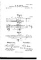
- Figure l is a side elevation of the entire machine, partly in section, and Fig. 2 is a corresponding plan view, partly in section.
- the remaining figures represent certain parts on a larger scale and detached.
- A is a strong fixed frame-work of cast-iron.
- B is an upright shaft, adapted to be operated by a pulley, B2, and carrying an expanded head or chuck, B1, which is partially flat and partially hollow, and is of proper size and form-to allow the finished article to lie upon its upper face with the dome downward.
- C is a center-pin, mounted concentrically in the shaftrB and held up by the force of a gentle spring, D. The upper end of this pin is contracted, forming a smaller pin above the shoulder, as indicated by c. Its lower end is formed with an enlargement, C', which prevents its being lifted entirely out by the force of the spring D.
- the adjustable frame E carries also a rack, E4, which receives the teeth of a geared segment, G, by turning which latter the frame E and its attachments may be raised and lowered at will.
- Anti-friction rollers e of which four are represented and more or less may suffice, turn upon centers mounted upon the inner edge of the adjustable frame E. These rollers c press forcibly downward upon the ring M.
- Another set of rollers, c' the pivots of which are also xed in the adjustable frame E, act against the inner surface of the loose ring M, and keep it in its proper concentric position. These latter act under an internal lip at the upper edge of the ring M, to support the weight thereof when it is elevated.
- This piece E5 which I have termed a bar, is' properly formed to afford a iirm hold for the horizontal 'carriage J, and allows the latter sufficient motion to move the spinning-rollen' from a little outside of the dome part inward to the center of the blank, or the center of the pin c.
- the vertical slide I carries a roller, I which acts against the under face of a cam-piece, EG, which is mounted on the side of the bar E5.
- a grooved upright shaft, K driven by gearing or belting from any suitable source, is supported by the framing A near its lower end, and by an imperfect steadying in the removable bearing afforded by the extended bar E5.
- This bar carries a bevel-gear wheel, N, which is feathered upon the upright shaft K, so that it is free to move up and down thereon, and will receive rotary motion therefrom in all positions.
- This wheel meshes into another bevel-gear wheel, O, which is xed on the feed-screw or feed-shaftP.
- the carriage J takes hold of the feed-screw, and is fed inward by the action thereof, carrying with it the vertical slide I and spinning-roller @',with the proper slow motion to perfectly raise, or rather, in the position here held, depress the dome.
- the partial nut j is mounted in a vertical groove in the carriage J and subjected to the action of a cam not represented, which is ixed on the partial-rotating shaft U.
- This shaft has an arm, u, which, when the carriage J has reached the extreme inward limit of its motion, strikes a stop, ET, mounted on or under the bar E5, and causes the shaft U to turn, and, by its cam, lift the partial nutj.
- a spring, F is employed to hold up the slide I and keep the roller I tightly in contact with the campiece E6.
- F a spring
- a slide, V is employed to raise and lower the partial nut j.
- the arrangement for this purpose is clearly shown in the figures.
- the slide V strikes a stop, E7, when the carriage J has reached the inward extreme of its motion, and, being moved endwise on the car ⁇ riage acts, by means of its inclined slot (see Fig. 5) on a crank-pin, x, carried on an arm, m1.
- This arm m1 is fixed on a short horizontal shaft, X, which, by means of another arm, m2, takes hold of the partial nut j.
- .Q is an adjustable block or sheet support, mounted by means of the screw g in an arm, which extends downward from the bar E5. It may be adjusted in a slot, so as to allow for some variations in the diameter of the article. Its lower face .presses gently on or stands rigidly above the upper face of the rapidly-revolving sheet metal.
- the adjustable frame E with the sets of anti-friction rollers e e', in combination with the loose ring M, chuck B1, and mechanism for spinning a dome in the center, substantially as herein specified.
- cam-piece E6 in combination with the spinning-roller i and its carrying means I IJ and feeding means P, adapted to serve in connection with the chuck B1 and holdingring M, as and forthe purposes herein specified.
- the yielding center pin C having a shoulder near its point, as represented, in combination with the chuck B1, holding-rin g M, and means for raising the center by spinning the metal into a recess in the chuck, as herein specified.
Landscapes
- Engineering & Computer Science (AREA)
- Mechanical Engineering (AREA)
- Shaping Metal By Deep-Drawing, Or The Like (AREA)
Description
i w. M. Conaza.
Machines for Spinning Sheet-Metal. l NO 157272. Patented Dec.1,1874.
v 3Sheets--Sheet 1.
mmnsQ/a; xm mxhv UNITED STATES PATENT OFFICE.'
WALTER M. CONGER, OF NEWARK, NEW JERSEY.
IMPROVEMENT IN MACHINES FOR SPINNING SHEET METAL.
Specification forming part of Letters Patent No. l57,272, dated December 1, 1874 application filed February 10, 1874.
To all 'whom it may concern:v
Be it known that I, WALTER M. GoNeER, of Newark, in Essex county, in the State of New Jersey, have invented certain Improvements relating to Machines for Spinning Sheet Metal, of which the following isa specication:
The machine is intended mainly for spinning the sheet-metal stove-support described in previous patents to me; but it may be employed with advantage in spinning various dish-shaped articles where a broad fiange is desired to be preserved unaffected.
For making my stove-support I take tinned sheet-iron or other thin sheet metal, previously rolled to the proper thickness, and raise a dome, either plain or variously beaded, in the center. I wish to retain a large portion of the surface in the perfectly plane or liat condition in which I purchase it from the manufacturer of sheet metal.
In the ordinary spinning-machines, either the metal is held by the central portion and theportions nearer the periphery treated by the spinning-tool, or the metal is caused to turn by being acted on by wheels, acting by their peripheries upon the sheet metal in the manner of rollers. Either of these methods, as also all ordinary methods of stamping, are liable and almost certain to distort the portion which should remain plane. yMy present invention overcomes the difticulty by grasping the portion of the sheet metal which is to remain plane firmly between two iiat surfaces which, during the spinning operation, revolve with it and eii'ectually prevent it.. from being wrinkled or disturbed. lVhile it is held and thus revolved the portion within the plane ring is spun into the proper dome form, and I have so constructed the machine that the periphery is left clear to allow me to trim the edge and turn a bead thereon without releasing the metal from the machine. The domeis formed and the edge finished with a single introduction and removal of the metal.
The following is a description of what I consider the best means of carrying out the invention. The accompanying drawings form a part of this specification.
Figure l is a side elevation of the entire machine, partly in section, and Fig. 2 is a corresponding plan view, partly in section. The remaining figures represent certain parts on a larger scale and detached.
Similar letters of reference indicate corresponding parts in all the figures.
A is a strong fixed frame-work of cast-iron. B is an upright shaft, adapted to be operated by a pulley, B2, and carrying an expanded head or chuck, B1, which is partially flat and partially hollow, and is of proper size and form-to allow the finished article to lie upon its upper face with the dome downward. C is a center-pin, mounted concentrically in the shaftrB and held up by the force of a gentle spring, D. The upper end of this pin is contracted, forming a smaller pin above the shoulder, as indicated by c. Its lower end is formed with an enlargement, C', which prevents its being lifted entirely out by the force of the spring D. M is a stout ring of castiron, having' a plane lower face corresponding to the plane face of the head or chuck B1 below it. This ring M is mounted loosely, by means of rollers, upon an adjustable frame, E, of slightly smaller diameter, which is, by means of arms El, a central hub, E2, and a stout shaft or vertical slide, E3, adapted to be moved up and down in a suitable bearing in the overhan ging head of the iixed framing A. The adjustable frame E carries also a rack, E4, which receives the teeth of a geared segment, G, by turning which latter the frame E and its attachments may be raised and lowered at will.
To introduce the sheet metal I turn the segment G and raise the frame E with all its connected parts. I then introduce the sheet metal between the upper face of the chuck B1 and the lower face of the loose ring M. A hole, which has been previously punched by hand or otherwise in the center of the sheet metal, is caused to lit upon the contracted top c of the central spring-pin, and serves to center the work. Vhen, by turning the segmentI G, the frame E and its connections are lowered, the ring M presses its annular plane face firmly upon a corresponding surface of the sheet metal or blank and holds it between itself` and the plane portion of the chuck B1. In this state of things, when the chuck B1 commences to be revolved by the action of a Abelt (not represented) upon the pulley B2,
the ring M goes with it. Anti-friction rollers e, of which four are represented and more or less may suffice, turn upon centers mounted upon the inner edge of the adjustable frame E. These rollers c press forcibly downward upon the ring M. Another set of rollers, c', the pivots of which are also xed in the adjustable frame E, act against the inner surface of the loose ring M, and keep it in its proper concentric position. These latter act under an internal lip at the upper edge of the ring M, to support the weight thereof when it is elevated. A vertical slide, I, carryrying a spinning-roller, i, at its lower end, is mounted in a stout horizontal slide or'carriage, J, which is adapted to be moved bythe action of the feed-screw P in a line horizontally across the blank. It is guided in this movement by a stout bar, E5, which is fixed on the frame E, and extends across it, and also overhangs a long distance on one side, to support the geared end of the feed-screw. This piece E5, which I have termed a bar, is' properly formed to afford a iirm hold for the horizontal 'carriage J, and allows the latter sufficient motion to move the spinning-rollen' from a little outside of the dome part inward to the center of the blank, or the center of the pin c. The vertical slide I carries a roller, I which acts against the under face of a cam-piece, EG, which is mounted on the side of the bar E5. A grooved upright shaft, K, driven by gearing or belting from any suitable source, is supported by the framing A near its lower end, and by an imperfect steadying in the removable bearing afforded by the extended bar E5. This bar carries a bevel-gear wheel, N, which is feathered upon the upright shaft K, so that it is free to move up and down thereon, and will receive rotary motion therefrom in all positions. This wheel meshes into another bevel-gear wheel, O, which is xed on the feed-screw or feed-shaftP. The carriage J takes hold of the feed-screw, and is fed inward by the action thereof, carrying with it the vertical slide I and spinning-roller @',with the proper slow motion to perfectly raise, or rather, in the position here held, depress the dome.
When all the parts are properly operating,
vthe blank centered on the pin C and held firmly on a large part of its surface by being clamped between the revolving chuck B1 and the correspondingly-moving ring M, which is moved by the frictional contact therewith, the carriage J is moved slowly inward by the action of the feed-screw P, and the spinning-roller depresses or sinks the dome part of the stove-support or corresponding article. This operation commences at the periphery of the dome part and progresses successively inward. During this operation the center-pin C sinks by the yielding of the spring D, and allows the dome to sink without distortion, while holding or aiding to hold the whole iirmly in its properly-centered position. When this action has progressed until the spinning-rollerfi has reached the center of the blank, and stands exactly over the pin c, the hold on the feed-screw P is relaxed, and the carriage J is moved back with its attachments, by the force of the weight L pulling on the cord l, which passes over the pulley l. A spring may serve instead of a weight, if preferred.
I release the carriage from the action of the feed-screw P by causing the partial nutj to be lifted out of contact with the feed-screw P as soon as the spinning-roller t' has reached thc line of the axis of the spring-pin C. The partial nut j is mounted in a vertical groove in the carriage J and subjected to the action of a cam not represented, which is ixed on the partial-rotating shaft U. This shaft has an arm, u, which, when the carriage J has reached the extreme inward limit of its motion, strikes a stop, ET, mounted on or under the bar E5, and causes the shaft U to turn, and, by its cam, lift the partial nutj.
When the finished stove-support or analogous article has been removed and a new blank introduced, and the frame and its connections again depressed, ready for another operation, the hand of the attendant is applied upon the arm u, turning it up into the position repre. sented. The partial nut j is free to descend and again engage with the feed-screw P. I can employ a spring on the top of the carriage J to insure the prompt and complete depression of the partial nut j, if desired.
So soon as an engagement is'effected between j and the feed screw, the carriage J, with the connected spinning-roller, commences to be fed again slowly inward to sink the dome, as before.
In the detailed drawings, Figs. 3, 4, and 5,
the forms of the parts are somewhat modi fied, and a spring, F, is employed to hold up the slide I and keep the roller I tightly in contact with the campiece E6. In this modifcation, also, a slide, V, is employed to raise and lower the partial nut j. The arrangement for this purpose is clearly shown in the figures. The slide V strikes a stop, E7, when the carriage J has reached the inward extreme of its motion, and, being moved endwise on the car` riage acts, by means of its inclined slot (see Fig. 5) on a crank-pin, x, carried on an arm, m1. This arm m1 is fixed on a short horizontal shaft, X, which, by means of another arm, m2, takes hold of the partial nut j. The endwise movement of the slide V raises the partial nutj and the carriage J, and its attachments being then moved outward by a weight and cord, as before described, the parts remain inert until the hand of the attendant is applied to move ,the slide V inward again, and thus again depress the partial nut.
I prefer to make the cam-piece E6 detachable and exchangeable. l can also change the head or chuck B1. By changing these parts I can, by the same machine, make different sizes and shapes of domes. I can also, obviously, by a more extended alteration, employ larger or smaller chucks Bl, and larger nor smaller rings M, so as to make stove-supports of larger or smaller outside diameter.
In order to trim the periphery of the stovesupport, or analogous sheet-metal work, [can apply a suitable cutting-tool by hand or by machinery, square or irregular shape to a perfect circle. I provide means for beading the edge when thus trimmed.
.Q is an adjustable block or sheet support, mounted by means of the screw g in an arm, which extends downward from the bar E5. It may be adjusted in a slot, so as to allow for some variations in the diameter of the article. Its lower face .presses gently on or stands rigidly above the upper face of the rapidly-revolving sheet metal.
I act on the edge of thesheet metal, which is allowed to extend beyond this rm adjustable piece Q by means of a beading-roller, r, which is mounted on a lever, R, turning on a pivot mounted on the adjustable support S. This support S', held by the pinching-screw T in the desired position on the firm framing A, carries also a support, S, which is adapted to apply'uuder the sheet metal opposite to or directly under the flrm block Q. The edge of the sheet-metal being thus allowed to revolve, projecting only a little beyond the two firm supports Q S, may be readily curled over and beaded in the desired manner by the action of the roller 1'.
I claim as my invention in machines for spinning metal- 1. The adjustable frame E, with the sets of anti-friction rollers e e', in combination with the loose ring M, chuck B1, and mechanism for spinning a dome in the center, substantially as herein specified.
and thus reduce the previously- 2. The cam-piece E6, in combination with the spinning-roller i and its carrying means I IJ and feeding means P, adapted to serve in connection with the chuck B1 and holdingring M, as and forthe purposes herein specified.
3. The beading-roller r and its connections, in combination with the chuck B1, holding means E, and mechanism for raising the center, as herein specified.
4. In combination with the chuck B1 and adjustable frame E, and its connections, adapted to hold a blank, and the spinningroller fi and its connections, adapted to treat the central portion of such blank, the feedscrew P, connected with the carriage J, and receiving motion through the gear-wheel N, which is feathered upon the shaft K to allow for the elevation and depression of the feedscrew and its connected parts, as herein specifled.
5. The automatic liberation of the carriage J and its connections from the feed-screw P, by means of the stop E7 acting on the partial nut j to detach it from the screw l), in combination with the cord l for moving the carriage J outward, all substantially as herein specified.
6. The yielding center pin C, having a shoulder near its point, as represented, in combination with the chuck B1, holding-rin g M, and means for raising the center by spinning the metal into a recess in the chuck, as herein specified.
In testimony whereof I have hereunto set my hand this 7th day of February, 1874, in the presence of two subscribing witnesses.
WALTER M. GONGER.
Witnesses:
CHAs. C. HARBINsoN, Tnos. GILEs.
Publications (1)
| Publication Number | Publication Date |
|---|---|
| US157272A true US157272A (en) | 1874-12-01 |
Family
ID=2226682
Family Applications (1)
| Application Number | Title | Priority Date | Filing Date |
|---|---|---|---|
| US157272D Expired - Lifetime US157272A (en) | Improvement in machines for spinning sheet metal |
Country Status (1)
| Country | Link |
|---|---|
| US (1) | US157272A (en) |
Cited By (7)
| Publication number | Priority date | Publication date | Assignee | Title |
|---|---|---|---|---|
| US2624303A (en) * | 1948-07-06 | 1953-01-06 | United Aircraft Prod | Machine for metalworking |
| US2674216A (en) * | 1949-04-23 | 1954-04-06 | Dewey J Griffin | Sheet metal spinning machine |
| US4903515A (en) * | 1988-10-21 | 1990-02-27 | Park Hyong Kwon | Heating container manufacturing apparatus |
| US20140020505A1 (en) * | 2007-10-29 | 2014-01-23 | Prestolite Performance, Llc | Method, system and apparatus to provide for universal bellhousing between engine and transmission of vehicle |
| US10054168B2 (en) | 2011-01-26 | 2018-08-21 | Accel Performance Group Llc | Clutch assembly cover, method of making same, and optional heat management |
| US10502306B1 (en) | 2016-04-25 | 2019-12-10 | Accel Performance Group Llc | Bellhousing alignment device and method |
| US10876594B2 (en) | 2011-01-26 | 2020-12-29 | Accel Performance Group Llc | Automotive flywheel with fins to increase airflow through clutch, and heat management method |
-
0
- US US157272D patent/US157272A/en not_active Expired - Lifetime
Cited By (10)
| Publication number | Priority date | Publication date | Assignee | Title |
|---|---|---|---|---|
| US2624303A (en) * | 1948-07-06 | 1953-01-06 | United Aircraft Prod | Machine for metalworking |
| US2674216A (en) * | 1949-04-23 | 1954-04-06 | Dewey J Griffin | Sheet metal spinning machine |
| US4903515A (en) * | 1988-10-21 | 1990-02-27 | Park Hyong Kwon | Heating container manufacturing apparatus |
| US20140020505A1 (en) * | 2007-10-29 | 2014-01-23 | Prestolite Performance, Llc | Method, system and apparatus to provide for universal bellhousing between engine and transmission of vehicle |
| US9360100B2 (en) * | 2007-10-29 | 2016-06-07 | Accel Performance Group Llc | Method, system and apparatus to provide for universal bellhousing between engine and transmission of vehicle |
| US10393254B2 (en) | 2007-10-29 | 2019-08-27 | Accel Performance Group Llc | Universal bellhousing, system and method therefore |
| US11174934B2 (en) | 2007-10-29 | 2021-11-16 | Accel Performance Group Llc | Universal bellhousing, system and method therefore |
| US10054168B2 (en) | 2011-01-26 | 2018-08-21 | Accel Performance Group Llc | Clutch assembly cover, method of making same, and optional heat management |
| US10876594B2 (en) | 2011-01-26 | 2020-12-29 | Accel Performance Group Llc | Automotive flywheel with fins to increase airflow through clutch, and heat management method |
| US10502306B1 (en) | 2016-04-25 | 2019-12-10 | Accel Performance Group Llc | Bellhousing alignment device and method |
Similar Documents
| Publication | Publication Date | Title |
|---|---|---|
| US157272A (en) | Improvement in machines for spinning sheet metal | |
| US406225A (en) | Cork machine | |
| US286115A (en) | Jules chaumont | |
| US452495A (en) | lindner | |
| US1175969A (en) | Turning and fluting machine. | |
| US658082A (en) | Apparatus for perforating designs in sheet metal. | |
| US238535A (en) | shaplbt | |
| US425809A (en) | Machine for decorating watch-cases | |
| US946508A (en) | Woodworking-machine. | |
| US1187365A (en) | Multiple-spindle drilling-machine. | |
| US65950A (en) | John eupp | |
| US1288147A (en) | Furnace-top-burring machine. | |
| US562172A (en) | Machine for dressing wheel-rims or the like | |
| US216308A (en) | Improvement in machines for reducing coin-blanks | |
| US135998A (en) | Improvement in engraving and carving machines | |
| US794375A (en) | Grinding mechanism. | |
| US128289A (en) | Improvement in molding-machines | |
| US375705A (en) | Engraving machine for multiple combinations | |
| US895180A (en) | Finger-ring-marking machine. | |
| US565859A (en) | kellogg | |
| US279853A (en) | atkinson | |
| US327122A (en) | And geoe | |
| US1587433A (en) | Adjustable curling die | |
| US750209A (en) | Automatic turning-machine | |
| US366778A (en) | keller |