US1555152A - Wheel jack - Google Patents
Wheel jack Download PDFInfo
- Publication number
- US1555152A US1555152A US39977A US3997725A US1555152A US 1555152 A US1555152 A US 1555152A US 39977 A US39977 A US 39977A US 3997725 A US3997725 A US 3997725A US 1555152 A US1555152 A US 1555152A
- Authority
- US
- United States
- Prior art keywords
- wheel
- frame
- jack
- base
- horizontal
- Prior art date
- Legal status (The legal status is an assumption and is not a legal conclusion. Google has not performed a legal analysis and makes no representation as to the accuracy of the status listed.)
- Expired - Lifetime
Links
Images
Classifications
-
- B—PERFORMING OPERATIONS; TRANSPORTING
- B66—HOISTING; LIFTING; HAULING
- B66F—HOISTING, LIFTING, HAULING OR PUSHING, NOT OTHERWISE PROVIDED FOR, e.g. DEVICES WHICH APPLY A LIFTING OR PUSHING FORCE DIRECTLY TO THE SURFACE OF A LOAD
- B66F5/00—Mobile jacks of the garage type mounted on wheels or rollers
- B66F5/02—Mobile jacks of the garage type mounted on wheels or rollers with mechanical lifting gear
- B66F5/025—Mobile jacks of the garage type mounted on wheels or rollers with mechanical lifting gear screw-actuated
Definitions
- This invention relates to an improved jack which is especially, but not necessarily designed for use in public garages and the like, and its purpose is to enable a single mechanic to remove a comparatively heavy wheel and tire by himself, a job ordinarily requiring the service of two or more mete chanics.
- the invention has more specific reference to a portable structure embodying a frame adapted to be raised and lowered, this frame being equipped with retaimng means whereby the wheel and tire, as a unlt, are held thereon.
- Figure 1 is a slde elevational view of a jack constructed in accordance with the present invention.
- Figure 2 is a front or inside vlew wlth the wheel removed.
- Figure 3 is a top plan view of Figure Figure 1 is a horizontal sectional view through the upright.
- Figure 5 is a fragmentary sectional and elevational view taken vertically through a portion of said upright.
- the reference character 1 designates what may be generally referred to as a base.
- the base is preferably composed of a pair of spaced parallel channel bars provided with a pinrality of appropriate casters 3, thus forming what may be said to be a truck.
- This upright comprises spaced vertical standards 5 connected together at their tops by a cross bar or rod 6, and secured at their bottoms to a horizontal channel bar 7.
- This channel bar is secured to the aforesaid channel bars 2.
- Suitable braces 9 are employed and arranged at the most desirable point for securing rigidity of structure.
- the standards 5 are composed of agle bars and strips 10.
- the strips are disposed in spaced parallelism with one flange to provide guideways for a substantially rectangular frame 11.
- This frame is made up of horizontal and vertical members, the ends of the horizontal ones of which are slidable in the guideways.
- Bracketached to the lower horizontal bar of the frame is a pair of right angle brackets serving as wheel rests for the wheel 13 shown in Figure 1.
- These brackets are preferably of the angular formation shown more plainly in Figure 1.
- Blocks 16 are slidably and adjustably mounted upon the arms 14 and carry wheel confining members 17 of right angular formation, and fingers 18 are adjustable upon these members to accommodate different widths of wheels.
- I For the purpose of raising the frame and wheel retaining means together I provide a depending screw 19 fastened to the center of the horizontal lower bar of said frame, and this extends downwardly through an inverted U-shaped member 20, upon which a feed nut 21 rests.
- the nut is equipped with a handle 22, or with spanner wrench sockets.
- a wheel supported base an upright rising from said base, said upright comprising spaced vertical standards, a frame vertically adjustable upon said standards, hoisting and lowering means for said'frame, a pair of angular brackets mounted on said frame and serving as wheel'rests, and horizontally adjustable wheel engaging devices also mounted on said frame and cooperable with the upper portion of the wheel for holding it in position on said rests.
- a wheelojack of the class described comprising a base, said base including spaced parallel anglebars, casters-connected to said angle bars, standards rising from said base, a frame vertically adjustable upon said standards, hoisting and lowering means interposed between the frame and base, angular brackets carried by said frame, horizontal arms carried by said frame, and
Description
Sepfz. 29 1925.
1,555,152 a... PAssow WHEEL JACK Filed June 27, 1925 2 Sheets-Sheet 1 (Tnoinca L. PASSOW WHEEL JACK Sept. 29, 1925.
Filed June 2'7. 1925 2 Sheets-Sheet 2 Patented Sept. 29, 1925.
UNITED STATES LOUIS PASSOW, F SAGINAW, MICHIGAN.
WHEEL JACK.
Application filed June 27, 1925. Serial No. 39,977.
To all whom it may concern:
Be it known that I, Lours PASSOW, a cit zen of the United States, residing at Saginaw, in the county of Saginaw and State of Michigan, have invented certaln new and useful Improvements in a Wheel Jack, of which the following is a specification.
This invention relates to an improved jack which is especially, but not necessarily designed for use in public garages and the like, and its purpose is to enable a single mechanic to remove a comparatively heavy wheel and tire by himself, a job ordinarily requiring the service of two or more mete chanics.
The invention has more specific reference to a portable structure embodying a frame adapted to be raised and lowered, this frame being equipped with retaimng means whereby the wheel and tire, as a unlt, are held thereon.
The specific details and their relative arrangement and association w1ll become apparent from the following descrlptlon and drawing.
In the accompanying drawing formmg a part of this application and inwhich like numerals are employed to designate llke parts throughout the same:
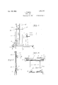
Figure 1 is a slde elevational view of a jack constructed in accordance with the present invention.
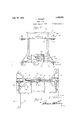
Figure 2 is a front or inside vlew wlth the wheel removed.
Figure 3 is a top plan view of Figure Figure 1 is a horizontal sectional view through the upright.
Figure 5 is a fragmentary sectional and elevational view taken vertically through a portion of said upright.
Referring to' the drawing in detail, the reference character 1 designates what may be generally referred to as a base. The base is preferably composed of a pair of spaced parallel channel bars provided with a pinrality of appropriate casters 3, thus forming what may be said to be a truck.
Supported from this truck or base is an upright 4. This upright comprises spaced vertical standards 5 connected together at their tops by a cross bar or rod 6, and secured at their bottoms to a horizontal channel bar 7. This channel bar is secured to the aforesaid channel bars 2. Suitable braces 9 are employed and arranged at the most desirable point for securing rigidity of structure. At this time attention is directed to the fact that the standards 5 are composed of agle bars and strips 10. By referring to Figure 4 it will be seen that the strips are disposed in spaced parallelism with one flange to provide guideways for a substantially rectangular frame 11. This frame is made up of horizontal and vertical members, the ends of the horizontal ones of which are slidable in the guideways. At
tached to the lower horizontal bar of the frame is a pair of right angle brackets serving as wheel rests for the wheel 13 shown in Figure 1. These brackets are preferably of the angular formation shown more plainly in Figure 1. Cooperative with the brackets are arms 14 fastened attheir inner ends to the frame and offset as shown at 15. Blocks 16 are slidably and adjustably mounted upon the arms 14 and carry wheel confining members 17 of right angular formation, and fingers 18 are adjustable upon these members to accommodate different widths of wheels.
- For the purpose of raising the frame and wheel retaining means together I provide a depending screw 19 fastened to the center of the horizontal lower bar of said frame, and this extends downwardly through an inverted U-shaped member 20, upon which a feed nut 21 rests. By preference the nut is equipped with a handle 22, or with spanner wrench sockets.
From the foregoing description it is obvious that after the wheel and axle or the complete chassis of the vehicle is jacked up in the usual way, the supplemental and improved jack devised by me is moved in place as indicated in Figure 1. The angular brackets 12 are brought up against the bottom or periphery of the tire of the wheel, and the confining members 17 and 18 are adjusted to hold the wheel in place. It will be noted that suflicient room is provided between the parts to facilitate work by the mechanic on the wheel. Moreover, it is understood that the adjustment of the frame is accomplished through the medium, of the nut and bolt or screw. If it is desired to move a comparatively heavy truck wheel from place to place in the garage, after taking it off, it is obvipus that this may be easily done with the improved jack structure.
While the preferred embodiment of the invention has been shown and described, it is to be understood that minor changes coming within the field of invention claimed may be resorted to if desired.
Having thus described the invention, what I claim as new and desire to secure by Letters Patent is 1. In a jack of the class described, a wheel supported base, an upright rising from said base, said upright comprising spaced vertical standards, a frame vertically adjustable upon said standards, hoisting and lowering means for said'frame, a pair of angular brackets mounted on said frame and serving as wheel'rests, and horizontally adjustable wheel engaging devices also mounted on said frame and cooperable with the upper portion of the wheel for holding it in position on said rests.
2. A wheelojack of the class described comprising a base, said base including spaced parallel anglebars, casters-connected to said angle bars, standards rising from said base, a frame vertically adjustable upon said standards, hoisting and lowering means interposed between the frame and base, angular brackets carried by said frame, horizontal arms carried by said frame, and
wheel clamps horizontally adjustable on said arms. I
In testimony whereof I- aifix my signature.
LOUIS PASSOW.
Priority Applications (1)
| Application Number | Priority Date | Filing Date | Title |
|---|---|---|---|
| US39977A US1555152A (en) | 1925-06-27 | 1925-06-27 | Wheel jack |
Applications Claiming Priority (1)
| Application Number | Priority Date | Filing Date | Title |
|---|---|---|---|
| US39977A US1555152A (en) | 1925-06-27 | 1925-06-27 | Wheel jack |
Publications (1)
| Publication Number | Publication Date |
|---|---|
| US1555152A true US1555152A (en) | 1925-09-29 |
Family
ID=21908406
Family Applications (1)
| Application Number | Title | Priority Date | Filing Date |
|---|---|---|---|
| US39977A Expired - Lifetime US1555152A (en) | 1925-06-27 | 1925-06-27 | Wheel jack |
Country Status (1)
| Country | Link |
|---|---|
| US (1) | US1555152A (en) |
Cited By (10)
| Publication number | Priority date | Publication date | Assignee | Title |
|---|---|---|---|---|
| US2429723A (en) * | 1944-10-30 | 1947-10-28 | Bearl F Kelley | Wheel lifting truck |
| US2479100A (en) * | 1945-06-22 | 1949-08-16 | Connor Engineering And Mfg Com | Dolly jack for airplanes |
| US2503138A (en) * | 1947-04-18 | 1950-04-04 | John W Smith | Vehicle wheel supporting truck |
| US2543296A (en) * | 1947-06-24 | 1951-02-27 | Percy W Dunn | Tire and wheel dolly and lift |
| US2600740A (en) * | 1947-09-04 | 1952-06-17 | Drum Corp | Wheel changing device |
| US3301419A (en) * | 1965-07-14 | 1967-01-31 | Harris L Molden | Wheel lift |
| US3749265A (en) * | 1971-12-28 | 1973-07-31 | R Smith | Wheel dolly |
| US4123038A (en) * | 1977-07-15 | 1978-10-31 | Meyers Gilbert D | Wheel lift |
| WO1990009949A1 (en) * | 1989-03-03 | 1990-09-07 | Gros Jean Charles | Mechanical device for moving heavy objects |
| US20060181057A1 (en) * | 2004-12-30 | 2006-08-17 | Kollarits Matthew D | Wheel jack |
-
1925
- 1925-06-27 US US39977A patent/US1555152A/en not_active Expired - Lifetime
Cited By (10)
| Publication number | Priority date | Publication date | Assignee | Title |
|---|---|---|---|---|
| US2429723A (en) * | 1944-10-30 | 1947-10-28 | Bearl F Kelley | Wheel lifting truck |
| US2479100A (en) * | 1945-06-22 | 1949-08-16 | Connor Engineering And Mfg Com | Dolly jack for airplanes |
| US2503138A (en) * | 1947-04-18 | 1950-04-04 | John W Smith | Vehicle wheel supporting truck |
| US2543296A (en) * | 1947-06-24 | 1951-02-27 | Percy W Dunn | Tire and wheel dolly and lift |
| US2600740A (en) * | 1947-09-04 | 1952-06-17 | Drum Corp | Wheel changing device |
| US3301419A (en) * | 1965-07-14 | 1967-01-31 | Harris L Molden | Wheel lift |
| US3749265A (en) * | 1971-12-28 | 1973-07-31 | R Smith | Wheel dolly |
| US4123038A (en) * | 1977-07-15 | 1978-10-31 | Meyers Gilbert D | Wheel lift |
| WO1990009949A1 (en) * | 1989-03-03 | 1990-09-07 | Gros Jean Charles | Mechanical device for moving heavy objects |
| US20060181057A1 (en) * | 2004-12-30 | 2006-08-17 | Kollarits Matthew D | Wheel jack |
Similar Documents
| Publication | Publication Date | Title |
|---|---|---|
| US1555152A (en) | Wheel jack | |
| US9022355B1 (en) | Hydraulic jack attachment | |
| US3252590A (en) | Apparatus for tilting motor cars | |
| US1515915A (en) | Portable repair unit | |
| US3292902A (en) | Portable tire lift | |
| US2781920A (en) | Adjustable supporting racks | |
| US968315A (en) | Combined jack and truck. | |
| US1559453A (en) | Welding table | |
| US1527901A (en) | Elevating bench | |
| US2036459A (en) | Adjustable auto hood paint rack | |
| US1965260A (en) | Automobile wheel lifter | |
| US2514781A (en) | Tire applying device | |
| US1593801A (en) | Edward f | |
| US2418586A (en) | Car door hanging truck | |
| US1598413A (en) | Automobile jack | |
| US1334336A (en) | Automobile-tilting machine | |
| US2836883A (en) | Device for removing parts from a tractor | |
| US1937833A (en) | Wheel and rim holder for automobiles | |
| US2131281A (en) | Trailer jack | |
| US1378582A (en) | Dual-wheel remover | |
| US1679107A (en) | Hand truck | |
| US1701242A (en) | Lifting jack for automobiles | |
| US2210085A (en) | Wheel and tire carrier | |
| US1738205A (en) | Vehicle jack | |
| JP2008162570A (en) | Tire replacement jack |