US1545936A - Pump - Google Patents
Pump Download PDFInfo
- Publication number
- US1545936A US1545936A US706090A US70609024A US1545936A US 1545936 A US1545936 A US 1545936A US 706090 A US706090 A US 706090A US 70609024 A US70609024 A US 70609024A US 1545936 A US1545936 A US 1545936A
- Authority
- US
- United States
- Prior art keywords
- piston
- follower
- packing
- pump
- rod
- Prior art date
- Legal status (The legal status is an assumption and is not a legal conclusion. Google has not performed a legal analysis and makes no representation as to the accuracy of the status listed.)
- Expired - Lifetime
Links
Images

Classifications
-
- F—MECHANICAL ENGINEERING; LIGHTING; HEATING; WEAPONS; BLASTING
- F04—POSITIVE - DISPLACEMENT MACHINES FOR LIQUIDS; PUMPS FOR LIQUIDS OR ELASTIC FLUIDS
- F04B—POSITIVE-DISPLACEMENT MACHINES FOR LIQUIDS; PUMPS
- F04B53/00—Component parts, details or accessories not provided for in, or of interest apart from, groups F04B1/00 - F04B23/00 or F04B39/00 - F04B47/00
- F04B53/14—Pistons, piston-rods or piston-rod connections
- F04B53/143—Sealing provided on the piston
Definitions
- This invention relates to improvements in pumps and more particularly to an improvement in the construction of slush pumps and has for a primary object thereof the provif sion of means whereby the packing of the pump may be compressed while the pump is in operation and a lubricant likewise fed to the pump piston during operation.
- shut-downs are undesirable for the reason that during such shut-downs, the water not being in circulation, sediment has a tendency to collect at the bottom of the bore being formed interfering seriously with starting up of the drill at the end. of the shut-down and generally causingannoyance to the drillers outside of the loss of time in the drilling operation.
- a further and still more specific objectof the invention is to provide an adjusting means for the packing whereby the packing may be adjusted during operation of the pump forming a grease barrel and having means adjustable longitudinally thereof for forcing the grease contained in the barrel through port-s in the rod and piston to the walls of the cylinder of the pump.
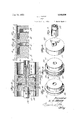
- Figure 1 is a vertical sectional view through the cylinder of the water end of a slush pump constructed in accordance with my invention, the piston being shown in elevation;
- - Figure 2 is an enlarged detail sectional view through the piston and a portion of the rod;
- Figure 3 is a further enlarged detail View in section showing the grease space formed between the cylinder, piston and the packings of the piston;
- Figure 4 is a perspective of the piston proper
- Figure 5 is a perspective of the intermediate follower head
- Figure 6 is a perspective of the follower
- Figure 7 is a perspective of the follower head engaging end of the adjusting element for the follower
- Figure 8 is a perspective view showing the construction and mounting of the grease or lubricant feeding follower contained within the follower head adjusting element;
- Fig. 9 is a detailed cross-sectional view of the upper end of the adjusting sleeve.
- the numeral 10 genera ly indicates the water cylinder of a slush pump and 11 and 12 the piston and rod heads of the cylinder.
- a rod 13 operates in the usual manner.
- the rod at the piston end thereof is provided with a taper 14 spaced from such end and taperin toward such end.
- the straight portion of t e rod beyond the taper in forming the end is divided into a plain section 15 arranged next adjacent the taper 14 and a threaded section 16 extending to the end of the rod.
- rllhe piston proper is seated upon the taper of the rod and has its periphery rabbetted at that end thereof next adjacent the piston head as indicated at 18.
- rlhis rabbet receives a packing 19 and the end of a flange 2() formed upon what l term an intermediate follower head 21 slidably mounted upon the straight portion 15 of the rod 13.
- the periphery of he intermediate follower head 21 at that side thereof next adjacent the piston end head 11 of the cylinder is provided with a rabbet 22 similar to the rabbet 18 of the piston 17 and this rabbet receives a packing 23 and a flange 24 formed upon a follower head 25 threaded upon the section 16 of the rod 13.
- the flange 20 of the intermediate follower head is provided in approximate alignment with the front face of the follower head or that face next adjacent the piston 17 and in its periphery with an annular groove 26 and through the ange are formed radially directed openings 27 kplacing the space between the piston 17 and intermediate follower head 21 in communication with the groove 2'6.
- rlhe straight portion 15, 16 of the rod is provided with a longitudinal bore 28 which at its rear end opens through the end of the rod and at its forward end communicates with a radial outlet port or ports 29 communicating with the space 30 between the piston and intermediate follower head at a point immediately rearwardly of the rear face of the piston head 17 lt will be obvious that lubricant fed longitudinally of the groove 28 will enter the space 30 and from this space will pass through the radial openings 27 to the groove 22. lt is pointed out that lubricant so delivered to the face of the piston and to the cylinder walls is delivered intermediate the packings 19 and 23 and accordingly in passing through these packings will tend to remove from the faces thereof any collected grit or dirt.
- the piston end head 11 of the cylinder is provided with a bore 32 aligned with the piston 13, the outer end of this bore being enlarged as at 33.
- a gland liange 34 is formed which is preferably threaded interiorly and exteriorly.
- a sleeve 35 which extends through and fits the bore 32.
- the piston follower 25 and the inner end of the sleeve 35 are provided with coacting clutch teeth, as at 36, so that upon rotation of the sleeve 35 the follower head 25 is rotated.
- the enlargement 33 of the bore 32 has packing 37 disposed therein which is compressed by a gland nut 38 engaged with the interior threads of the gland flange 34.
- the outer end of the sleeve 35 is exteriorly threaded, as at 39, for engagement by a cap 40 the exterior of which is shaped for engagement by a wrench whereby the sleeve may be rotated, the sleeve being so constructed that it abuts the inner end of the bore of the cap to limit its movement upon the sleeve.
- this sleeve is interiorly relieved, as at 4l, to form a shoulder 42 against which is seated a supporting disk 43, this disk being of less thickness than the depth of the relief 41. so that when seated against the shoulder 42 at the forward end of this relief it is spaced from the .adjacent face of the end of the cap 40.
- the disk and cap are formed with axial bores 44, 45 through which are rotatably directed a shaft 46, the shaft, intermediate the adjacent faces of the cap and disk, being provided with an enlargement 47 which prevents displacement of the shaft.
- the outer end of the shaft is formed for engagement with a wrench, as at 48, while the inner end thereof which projects into the sleeve 35 for a considerable distance is threaded, the inner extremity of the shaft being provided with a removable stop member 49.
- a follower head 50 mounted upon the shaft is a follower head 50 having threaded engagement therewith, so that upon rotation of the shaft the head is forced longitudinally of the sleeve to drive before it the lubricant contained within the sleeve.
- Means are provided, as at 51, and in the present instance shown as consisting of a guide rod carried by the disk 43, forpreventing rotation of the follower head within the sleeve.
- a housing therefor is preferably provided consisting of a sleeve 52 threaded at its inner end for engagement with the outer face of the gland flange 34 and at its outer end for engagement by a cap 53, this sleeve being bodily removable to afford access for adjustment of the sleeve 35 or shaft 46.
- the device packing is placed in the rabbets 18 and 26 and the complete piston assembled, the sleeve 35 placed in position, after which the head 11 is placed upon the cylinder. , The sleeve 35 is then filled with grease or other lubricant and the disk 43 and shaft 46 placed in position, the follower head 50 having been first Withdrawn until it lies immediately adjacent the disk 43. The cap 40 is then placed in position and tightened until sufficient pressure has been placed upon the packing, after which the shaft 46 is rotated to force the lubricant well into the spaces 30 and 3l. The protecting casing is then placed in position and the pump may be operated. When further adjustments are necessary these may be made without stopping the pump, if so desired, or if the pump is stopped it.
- apump of the character described a cylinder, a piston operating therein, packings carried by the piston, and means disposed exteriorly of the pump for tightening said packings, the piston including relatively movable sections affording therebetween a chamber for the reception of liibricant, said means for tightening said packing relatively moving said 'sections during compression of the packing to lessen the size of the chamber, said chamber being in coinmunication with the exterior of the piston between the packings.
- a cylinder a piston operating therein and having a packing groove, packing disposed within the groove, a follower head associated with the piston compressing packings Within the groove, means for shifting said follower operable from the exterior of the cylinder of the pump, comprisinga hollow member operatively engaged with the follower and projecting through a packing gland carried by the cylinder head, said hollow member forming a grease chamber and being in communication with the outer surface of the piston head through the piston rod, and means for ejecting grease from the chamber.
- a cylinder In a pump of the character described, a cylinder, a piston operating therein and having a packing groove, packing disposed within the groove, a follower head associated with the piston compressing packings within the groove, means for shifting said follower operable from the exterior of the cylinder of the pump, comprising a hollow member operatively engaged with the hollow member forming a grease chamber and being in communication with the outer surface of the piston head through the piston rod, means for ejecting grease from the chamber including a follower disposed within the hollow member, and means for shifting the follower longitudinally of the hollow member disposed exteriorly of the pump.
- a pist0n having spaced packing grooves each having a packing therein, means for simultaneously compressing the packings within the grooves, and means for delivering a lubricant to the exterior of the piston between the packings including a chamber reduced in capacity by operation of said means to compress the packing.
- a piston havin spaced packing grooves each having a pacing therein, means for delivering a lubricant to the exterior of the piston between the packings including a lubricant storage chamber in communication with the exterior of the piston, and means operable yfrom the exterior of the cylinder for contracting the chamber.
- a rod a piston fixed upon the rod, a follower adjustable upon the rod and an intermediate follower disposed between the follower and piston and shiftable upon the rod, the piston and intermediate follower having peripheral packing receiving rabbets at the ends thereof next adjacent the follower, the follower and intermediate follower having portions entering the packing rabbets of the intermediate follower and piston respectively to compress the packings therein, the compressing portion of said intermediate follower being perforated to permit passage of a lubricant disposed in the space intermediate said piston and intermediate follower to the exterior of the piston, and means for delivering a lubricant longitudinally of the rod to such space.
- a rod a piston fixed upon the rod, a follower adjustable upon the rod and an intermediate follower disposed between the follower and piston and shiftable upon the rod, the piston and intermediate follower having peripheral packing receiving rabbets at the ends thereof next adjacent the follower, the follower and intermediate follower having portions entering the packing rabbets of the intermediate follower and piston respectively to compress the packings therein, the compressing portion of said intermediate follower being perforated to permit passage of a lubricant disposed in the space intermediate said piston and intermediate follower to the exterior of the piston, and means disposed exteriorly of the cylinder for shifting said follower head upon the rod to thereby compress the packings within said rabbets and decrease the space between the intermediate follower and piston and drive lubricant disposed in said space through such perforations.
- a piston having spaced packing grooves, each having a packing therein, means for simultaneously compressing the packings within the grooves, and a chamber in communication with the exterior of the piston between the grooves contracted upon operation of said means.
- a iston comprising relatively shiftable sectlons adapted to support therebetween a packing to be compressed upon shifting of the sections, the sections combining to provide a chamber, said chamber being in communication with the exterior of the piston and adapted for the reception of a lubricant, 'and means for relatively shifting said sections.
- a cylinder In a pump of the type described, a cylinder, a piston operating therein and comprising sections relatively shiftable longitudinally of the cylinder, a packing supported between the sections and adapted to be compressed upon such relative shifting of the sections, said sections combining to form a chamber for the reception of lubricant, the chamber being in communication with the exterior of the piston, and means operable exteriorly of the cylinder for relatively shifting said sections.l
Landscapes
- Engineering & Computer Science (AREA)
- Mechanical Engineering (AREA)
- General Engineering & Computer Science (AREA)
- Pistons, Piston Rings, And Cylinders (AREA)
Description
J. BLACK July 14, E925.
PUMP
2 Sheets-Sheet l Filed April l2 1924 www XM @vv R NM. A mum,
Juy 14, 1925.
L.. J. BLACK PUMP Filed April l2 1924 Y 2 Sheets-Sheet 2 Patented July 14, 1925.
PATENT OFFICE'.
LEE J'. BLACK, 0F BEAUMONT, TEXAS.
PUMP.
Application led April 12, 1924. Serial No. 706,090.
To all whom it may concern.'
Be it known that I, Las J. BLACK, a citi'- zen of the United States, residing at Beaumont, in the county of Jefferson and State of Texas, have invented certain new and useful Improvements in Pumps, of which the following is a specification.
This invention relates to improvements in pumps and more particularly to an improvement in the construction of slush pumps and has for a primary object thereof the provif sion of means whereby the packing of the pump may be compressed while the pump is in operation and a lubricant likewise fed to the pump piston during operation.
lt is well known to those familiar with the art that heavy duty slush pumps, such as are employed for circulating water in rotary well drilling apparatus, handle a class of fluid which carries a considerable amount of gritty substances with it and for this reason the-packing employed in the pump wears rapidly requiring frequent replacements or adjustments necessitating a shutdown of the pump and accordingly temporary shut-down of the drilling operation. rThese shut-downs are undesirable for the reason that during such shut-downs, the water not being in circulation, sediment has a tendency to collect at the bottom of the bore being formed interfering seriously with starting up of the drill at the end. of the shut-down and generally causingannoyance to the drillers outside of the loss of time in the drilling operation. Furthermore, the packing which is ordinarily employed on such a pump is difficult to lubricate. The application of oil or grease to the packing when applied serves only to lubricate the cylinder during the first few hours of the pumps use after such packing. After this period the heavy grit and dirt carried by the fluid which is being pumped rapidly carries away the grease and with the grease removed embeds itself in the packing, result- 'ject of this invention, as outlined above, is
the provision of apparatus permitting tightening of the packing without shutting down the pump and to feed a lubricant to the packing, and more specifically it is the purpose of this invention to so feed the lubricant to the packing that it will tend to recharacter in whiclrt-he means for adjusting or tightening the packing provides a means for introducing to the piston the lubricatf ing element employed.
A further and still more specific objectof the invention is to provide an adjusting means for the packing whereby the packing may be adjusted during operation of the pump forming a grease barrel and having means adjustable longitudinally thereof for forcing the grease contained in the barrel through port-s in the rod and piston to the walls of the cylinder of the pump.
The invention further resides in the n-ovel construction and arrangement of the various parts employed as disclosed in the accompanying drawings, wherein for the purpose of illustration is shown a preferred embodiment of my invention and wherein:-
Figure 1 is a vertical sectional view through the cylinder of the water end of a slush pump constructed in accordance with my invention, the piston being shown in elevation;
-Figure 2 is an enlarged detail sectional view through the piston and a portion of the rod;
Figure 3 is a further enlarged detail View in section showing the grease space formed between the cylinder, piston and the packings of the piston; v
Figure 4 is a perspective of the piston proper;
Figure 5 is a perspective of the intermediate follower head;
Figure 6 isa perspective of the follower;
Figure 7 is a perspective of the follower head engaging end of the adjusting element for the follower;
Figure 8 is a perspective view showing the construction and mounting of the grease or lubricant feeding follower contained within the follower head adjusting element;
Fig. 9 is a detailed cross-sectional view of the upper end of the adjusting sleeve.
Referring now more particularly to the drawings, .the numeral 10 genera ly indicates the water cylinder of a slush pump and 11 and 12 the piston and rod heads of the cylinder. Through a packing gland in the rod head 12 a rod 13 operates in the usual manner. ln accordance 'with this invention, the rod at the piston end thereof is provided with a taper 14 spaced from such end and taperin toward such end. The straight portion of t e rod beyond the taper in forming the end is divided into a plain section 15 arranged next adjacent the taper 14 and a threaded section 16 extending to the end of the rod.
rllhe piston proper, indicated at 17, is seated upon the taper of the rod and has its periphery rabbetted at that end thereof next adjacent the piston head as indicated at 18. rlhis rabbet receives a packing 19 and the end of a flange 2() formed upon what l term an intermediate follower head 21 slidably mounted upon the straight portion 15 of the rod 13. The periphery of he intermediate follower head 21 at that side thereof next adjacent the piston end head 11 of the cylinder is provided with a rabbet 22 similar to the rabbet 18 of the piston 17 and this rabbet receives a packing 23 and a flange 24 formed upon a follower head 25 threaded upon the section 16 of the rod 13. The flange 20 of the intermediate follower head is provided in approximate alignment with the front face of the follower head or that face next adjacent the piston 17 and in its periphery with an annular groove 26 and through the ange are formed radially directed openings 27 kplacing the space between the piston 17 and intermediate follower head 21 in communication with the groove 2'6. rlhe straight portion 15, 16 of the rod is provided with a longitudinal bore 28 which at its rear end opens through the end of the rod and at its forward end communicates with a radial outlet port or ports 29 communicating with the space 30 between the piston and intermediate follower head at a point immediately rearwardly of the rear face of the piston head 17 lt will be obvious that lubricant fed longitudinally of the groove 28 will enter the space 30 and from this space will pass through the radial openings 27 to the groove 22. lt is pointed out that lubricant so delivered to the face of the piston and to the cylinder walls is delivered intermediate the packings 19 and 23 and accordingly in passing through these packings will tend to remove from the faces thereof any collected grit or dirt. lt is, of course, understood that in the actual construction of the piston and cylinder the piston proper is slightly smaller than the cylinder in which it operates, the packing filling this space. Accordingly, between the wall of the piston and the wall of the cylinder and between the packings 19 and 23 a space 31 is formed in which the lubricant may collect. Accordingly, there will always be lubricantupon the surface of the piston between the packings for delivery to the walls of the cylinder. Attention is further directed to the fact that if the space 30 be filled with grease and the follower head 25 adjusted to tighten the packings 23, the grease or lubricant within the space 3() by the shifting movement of the intermediate follower head 21 will be compressed and forced outwardly through the openings 27 provided, of course, return of the grease through the ports 29, 28 is checked in any manner. 'llhus during the tightening operation grease is supplied to the walls of the cylinder.
The piston end head 11 of the cylinder is provided with a bore 32 aligned with the piston 13, the outer end of this bore being enlarged as at 33. About the edges of the bore upon the outer surface of the piston a gland liange 34 is formed which is preferably threaded interiorly and exteriorly. IThreaded upon the end 16 of the piston rod 13 is a sleeve 35 which extends through and fits the bore 32. The piston follower 25 and the inner end of the sleeve 35 are provided with coacting clutch teeth, as at 36, so that upon rotation of the sleeve 35 the follower head 25 is rotated. The enlargement 33 of the bore 32 has packing 37 disposed therein which is compressed by a gland nut 38 engaged with the interior threads of the gland flange 34. The outer end of the sleeve 35 is exteriorly threaded, as at 39, for engagement by a cap 40 the exterior of which is shaped for engagement by a wrench whereby the sleeve may be rotated, the sleeve being so constructed that it abuts the inner end of the bore of the cap to limit its movement upon the sleeve. i
rllhe outer end of this sleeve is interiorly relieved, as at 4l, to form a shoulder 42 against which is seated a supporting disk 43, this disk being of less thickness than the depth of the relief 41. so that when seated against the shoulder 42 at the forward end of this relief it is spaced from the .adjacent face of the end of the cap 40. The disk and cap are formed with axial bores 44, 45 through which are rotatably directed a shaft 46, the shaft, intermediate the adjacent faces of the cap and disk, being provided with an enlargement 47 which prevents displacement of the shaft. lThe outer end of the shaft is formed for engagement with a wrench, as at 48, while the inner end thereof which projects into the sleeve 35 for a considerable distance is threaded, the inner extremity of the shaft being provided with a removable stop member 49. Mounted upon the shaft is a follower head 50 having threaded engagement therewith, so that upon rotation of the shaft the head is forced longitudinally of the sleeve to drive before it the lubricant contained within the sleeve. Means are provided, as at 51, and in the present instance shown as consisting of a guide rod carried by the disk 43, forpreventing rotation of the follower head within the sleeve. In order to protect the outer end of the sleeve and shaft from damage by accidental engagement therewith, a housing therefor is preferably provided consisting of a sleeve 52 threaded at its inner end for engagement with the outer face of the gland flange 34 and at its outer end for engagement by a cap 53, this sleeve being bodily removable to afford access for adjustment of the sleeve 35 or shaft 46.
In the use of the device packing is placed in the rabbets 18 and 26 and the complete piston assembled, the sleeve 35 placed in position, after which the head 11 is placed upon the cylinder. ,The sleeve 35 is then filled with grease or other lubricant and the disk 43 and shaft 46 placed in position, the follower head 50 having been first Withdrawn until it lies immediately adjacent the disk 43. The cap 40 is then placed in position and tightened until sufficient pressure has been placed upon the packing, after which the shaft 46 is rotated to force the lubricant well into the spaces 30 and 3l. The protecting casing is then placed in position and the pump may be operated. When further adjustments are necessary these may be made without stopping the pump, if so desired, or if the pump is stopped it. will be obvious since all adjustments can be made from the exterior of the pump these will occupy but4 very few moments. Even though the pump is stopped for tightening the packing and appl ing lubricant to the packing it will be obvious that the protecting casing can be removed during the operation of the pump so that very little time will be lost by 'the shut-down, the time, in fact, being soshort that there is no necessity for a suspension of drilling operations.
It will be obvious that the specific construction hereinbefore set forth is intended only to illustrate a particular preferred form of my invention and is capable of a considerable range of change and modification without departing from the spirit of the invention and I accordingly do not limit 'myself to such specific structure except as hereinafter claimed.
I claim 1. In apump of the character described, a cylinder, a piston operating therein, packings carried by the piston, and means disposed exteriorly of the pump for tightening said packings, the piston including relatively movable sections affording therebetween a chamber for the reception of liibricant, said means for tightening said packing relatively moving said 'sections during compression of the packing to lessen the size of the chamber, said chamber being in coinmunication with the exterior of the piston between the packings.
2. In a pump of the character described, a cylinder, a piston operating therein and having a packing groove, packing disposed within the groove, a follower head associated with the piston compressing packings Within the groove, means for shifting said follower operable from the exterior of the cylinder of the pump, comprisinga hollow member operatively engaged with the follower and projecting through a packing gland carried by the cylinder head, said hollow member forming a grease chamber and being in communication with the outer surface of the piston head through the piston rod, and means for ejecting grease from the chamber. p
3. In a pump of the character described, a cylinder, a piston operating therein and having a packing groove, packing disposed within the groove, a follower head associated with the piston compressing packings within the groove, means for shifting said follower operable from the exterior of the cylinder of the pump, comprising a hollow member operatively engaged with the hollow member forming a grease chamber and being in communication with the outer surface of the piston head through the piston rod, means for ejecting grease from the chamber including a follower disposed within the hollow member, and means for shifting the follower longitudinally of the hollow member disposed exteriorly of the pump.
4. In a pump of the type described, a pist0n having spaced packing grooves each having a packing therein, means for simultaneously compressing the packings within the grooves, and means for delivering a lubricant to the exterior of the piston between the packings including a chamber reduced in capacity by operation of said means to compress the packing.
5. In a pump of the type described, a piston havin spaced packing grooves each having a pacing therein, means for delivering a lubricant to the exterior of the piston between the packings including a lubricant storage chamber in communication with the exterior of the piston, and means operable yfrom the exterior of the cylinder for contracting the chamber.
6. In a pump of the type described, a rod, a piston fixed upon the rod, a follower adjustable upon the rod and an intermediate follower disposed-between the follower and piston and shiftable upon the rod, the piston and intermediate follower having eri'pheral packing receiving rabbets at the ends thereof next adjacent the follower, the
follower and intermediate follower having portions entering the packing rabbets of` the intermediate follower and piston respectively to compress the packings therein, the compressing portion of said intermediate follower being perforated to permit passage of a lubricant-disposed in the space intermediate said piston and intermediate follower to the exterior of the piston.
7. Ina pump of the type described, a rod, a piston fixed upon the rod, a follower adjustable upon the rod and an intermediate follower disposed between the follower and piston and shiftable upon the rod, the piston and intermediate follower having peripheral packing receiving rabbets at the ends thereof next adjacent the follower, the follower and intermediate follower having portions entering the packing rabbets of the intermediate follower and piston respectively to compress the packings therein, the compressing portion of said intermediate follower being perforated to permit passage of a lubricant disposed in the space intermediate said piston and intermediate follower to the exterior of the piston, and means for delivering a lubricant longitudinally of the rod to such space.
8. In a pump of the type described, a rod, a piston fixed upon the rod, a follower adjustable upon the rod and an intermediate follower disposed between the follower and piston and shiftable upon the rod, the piston and intermediate follower having peripheral packing receiving rabbets at the ends thereof next adjacent the follower, the follower and intermediate follower having portions entering the packing rabbets of the intermediate ,follower and piston respectively to compress the packings therein, the compressing portion of said intermediate follower being perforated to permit passage of a lubricant disposed in the space intermediate said piston and intermediate follower` tothe exterior of the piston, .and means for delivering a lubricant longitudinally of the rod to such space operable from the exterior of the cylinder.
9. In a pump of the type described, a rod, a piston fixed upon the rod, a follower adjustable upon the rod and an intermediate follower disposed between the follower and piston and shiftable upon the rod, the piston and intermediate follower having peripheral packing receiving rabbets at the ends thereof next adjacent the follower, the follower and intermediate follower having portions entering the packing rabbets of the intermediate follower and piston respectively to compress the packings therein, the compressing portion of said intermediate follower being perforated to permit passage of a lubricant disposed in the space intermediate said piston and intermediate follower to the exterior of the piston, and means disposed exteriorly of the cylinder for shifting said follower head upon the rod to thereby compress the packings within said rabbets and decrease the space between the intermediate follower and piston and drive lubricant disposed in said space through such perforations. u
l0. In a pump of the type described, a piston having spaced packing grooves, each having a packing therein, means for simultaneously compressing the packings within the grooves, and a chamber in communication with the exterior of the piston between the grooves contracted upon operation of said means.
11. A iston comprising relatively shiftable sectlons adapted to support therebetween a packing to be compressed upon shifting of the sections, the sections combining to provide a chamber, said chamber being in communication with the exterior of the piston and adapted for the reception of a lubricant, 'and means for relatively shifting said sections.
12. In a pump of the type described, a cylinder, a piston operating therein and comprising sections relatively shiftable longitudinally of the cylinder, a packing supported between the sections and adapted to be compressed upon such relative shifting of the sections, said sections combining to form a chamber for the reception of lubricant, the chamber being in communication with the exterior of the piston, and means operable exteriorly of the cylinder for relatively shifting said sections.l
vIn testimony whereof I affix my signature.
LEE J. BLACK.
Priority Applications (1)
| Application Number | Priority Date | Filing Date | Title |
|---|---|---|---|
| US706090A US1545936A (en) | 1924-04-12 | 1924-04-12 | Pump |
Applications Claiming Priority (1)
| Application Number | Priority Date | Filing Date | Title |
|---|---|---|---|
| US706090A US1545936A (en) | 1924-04-12 | 1924-04-12 | Pump |
Publications (1)
| Publication Number | Publication Date |
|---|---|
| US1545936A true US1545936A (en) | 1925-07-14 |
Family
ID=24836180
Family Applications (1)
| Application Number | Title | Priority Date | Filing Date |
|---|---|---|---|
| US706090A Expired - Lifetime US1545936A (en) | 1924-04-12 | 1924-04-12 | Pump |
Country Status (1)
| Country | Link |
|---|---|
| US (1) | US1545936A (en) |
Cited By (4)
| Publication number | Priority date | Publication date | Assignee | Title |
|---|---|---|---|---|
| US2685886A (en) * | 1951-07-23 | 1954-08-10 | Garrett Oil Tools Inc | Pressure responsive valve |
| US2785025A (en) * | 1955-07-06 | 1957-03-12 | Wilson John Hart | Mud pump piston |
| US3704652A (en) * | 1969-06-09 | 1972-12-05 | Girling Ltd | Hydraulic brakes |
| US6016738A (en) * | 1994-11-10 | 2000-01-25 | Thomassen International B.V. | Piston compressor of the horizontal type |
-
1924
- 1924-04-12 US US706090A patent/US1545936A/en not_active Expired - Lifetime
Cited By (4)
| Publication number | Priority date | Publication date | Assignee | Title |
|---|---|---|---|---|
| US2685886A (en) * | 1951-07-23 | 1954-08-10 | Garrett Oil Tools Inc | Pressure responsive valve |
| US2785025A (en) * | 1955-07-06 | 1957-03-12 | Wilson John Hart | Mud pump piston |
| US3704652A (en) * | 1969-06-09 | 1972-12-05 | Girling Ltd | Hydraulic brakes |
| US6016738A (en) * | 1994-11-10 | 2000-01-25 | Thomassen International B.V. | Piston compressor of the horizontal type |
Similar Documents
| Publication | Publication Date | Title |
|---|---|---|
| US3894818A (en) | In-hole motors | |
| US2814465A (en) | Drill bits | |
| US2321927A (en) | Packing device | |
| US2301319A (en) | Plunger | |
| US3154158A (en) | Rock drill | |
| DE3010974A1 (en) | VALVE | |
| US2732805A (en) | Lucien | |
| DE69401384T2 (en) | Screw fluid machine | |
| DE3336540A1 (en) | IMPACT DRILLING MACHINE | |
| US2810550A (en) | Earth boring machine | |
| US2216353A (en) | Piston | |
| US1065332A (en) | Crusher. | |
| US2075017A (en) | Pump and method of silencing and operating pumps | |
| RU2119035C1 (en) | Rotary-spiral hydraulic motor | |
| DE102008034391A1 (en) | Hydraulic drive for use in mining region, has pressure controlled axial clearance compensation mechanisms such as guide plate, pressure plate, housing cover, screw and ball, compensating clearance of drive shaft | |
| US2789515A (en) | Variable stroke variable pressure pump or compressor | |
| US2123183A (en) | Pumping mechanism | |
| US1519478A (en) | Means for varying the delivery of pumps | |
| DE818607C (en) | Multi-cylinder piston pump | |
| US1558221A (en) | Lubricator for rock drills | |
| US2320571A (en) | Motor | |
| DE896458C (en) | Power control in rotary machines | |
| US1649196A (en) | Rotatably-driven reciprocating-piston pump | |
| US3063764A (en) | Wiper for plunger pumps | |
| US1980986A (en) | Pumping apparatus |