US1525035A - Packing apparatus - Google Patents
Packing apparatus Download PDFInfo
- Publication number
- US1525035A US1525035A US474335A US47433521A US1525035A US 1525035 A US1525035 A US 1525035A US 474335 A US474335 A US 474335A US 47433521 A US47433521 A US 47433521A US 1525035 A US1525035 A US 1525035A
- Authority
- US
- United States
- Prior art keywords
- receptacles
- conveyor
- packing apparatus
- shaft
- packing
- Prior art date
- Legal status (The legal status is an assumption and is not a legal conclusion. Google has not performed a legal analysis and makes no representation as to the accuracy of the status listed.)
- Expired - Lifetime
Links
Images


Classifications
-
- B—PERFORMING OPERATIONS; TRANSPORTING
- B65—CONVEYING; PACKING; STORING; HANDLING THIN OR FILAMENTARY MATERIAL
- B65B—MACHINES, APPARATUS OR DEVICES FOR, OR METHODS OF, PACKAGING ARTICLES OR MATERIALS; UNPACKING
- B65B1/00—Packaging fluent solid material, e.g. powders, granular or loose fibrous material, loose masses of small articles, in individual containers or receptacles, e.g. bags, sacks, boxes, cartons, cans, or jars
- B65B1/20—Reducing volume of filled material
- B65B1/22—Reducing volume of filled material by vibration
Definitions
- My invention relates generally to packingapparatus and more especially to apparatus useful in packing.puiverulent or granular materials, such, for example :as sugar, flour, salt, sand, cement, etc, into suitable receptacles or containers for convenient handlin in shipping. Close packing .of such materials to a high density is greatly facilitated by vibrating the receptacle either during, or after filling.
- this is an :old expedient in the art of packing pulverulent or granular materials, but in apparatus heretofore designed for this purpose, especially for packing such materials in comparat-ively large receptacles or barrels, extremely violent agitation was resorted. to, with the result that considerable of the material was expelled as dust. i side from the consideration of economy, practice. under the conditions aforesaid, was not only unsanitary, but, as in the case, for example, of flour, dangerous on account of susceptibility of the liberated particles to exp-1osion.
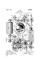
- Fig. I is an illustration showing :in plan, the gencra l layout of packing apparatus typical of my invention.
- Fig. II is a plan view, on an enlarged scale, of a portion of the apparatus showing No. 474,335. Renewed June 26, 1924.
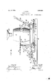
- Fig. III isan elevation of the organiza' tion shown in Fig. II, as it appears when viewed from the left of the latter figure.
- Fig. IV is :an elevation viewed from the lower side of Fig. II, t'he portions of the apparatus below the plane of the arrows IVIV having been omitted so as to avoid confusion,
- Fig. V is a sectional elevation of the agitating mechanism, the plane of section being indicated by the arrows VV in Fig. II.
- Fig. VI is a fragmentary detail view showing the meanswhereby the activity of the transfer spider is manually controlled.
- Figs. VII and VIII aredetail sectional. illustrations respectively viewed in the direction of the arrows VII-VII and VIII VIII in Fig. VI.
- a conveying system which includes two main, parallelly extending conveyors 1 and '2, and one or more transverse or auxiliary conveyors each comprising two separate sections such as designated at 3 and 4-.
- the main conveyor 1 may be of the ordinary endless type, capable of being actuated :under propulsion of any suitable driving means (not shown), and caused to travel, for example, in the direction indicated by the arrow thereon to progress the barrels B to position adjacent the transverse conveyor, or conveyors of the sys tem as the case may be.
- the barrels B are individually transferred, either manually or mechanical ly to the section 3 of the transversed conveyor, whereby the barrels are, in turn, -progressed to a vibrating mechanism comprehensively indicated at 5, shown as being interposed between the said conveyor section and the companion section 4. ,After having their contents well settled or packed under agitation.
- the barrels are finally successively transferred to the other main conveyor 2 for delivery to any convenient location or point in the plant for disposal.
- the transfer of the barrels from the section 4. of the transverse conveyor to the main delivery conveyor 2 may be effected either under manual guidance or automatically, as previously suggested, in connection with transfer between the main conveyor 1 and the section 3 of said transverse conveyor.
- the two sections of the transverse conveyor are driven in the same direction as indicated by the arrows in Figs. I and II, under support of drums 6, 6 and 7, 7 respectively, in a manner to be later disclosed herein.
- this mechanism includes a table 10 preferably of a size capable of conveniently accommodating the barrels B one at a time.
- Said table may be of any approved construct-ion and is herein shown as rigidly mounted to slide bars 11, 11 which are guided for horizontal reciprocation in appropriate bearings 12, 12 supported by an underlying frame 13. Vibratory motion is imparted to the table 10 through the aid of eccentrics 15, 15 on a shaft 16, the latter being journalled in bearings 17 supported by the frame 13 aforesaid.
- the shaft 16 is driven at such speed as to cause vibration of the table, through interposed instrumentalities just described, at a suit-able rate to effect thorough settling of the contents of the barrel thereon, but without so unduly agitating the contents as to result in forcible expulsion of any dust when comparatively fine material such as cement, or flour, is being packed.
- the shaft 16 has loosely mounted thereon a pulley 17 which is coordinated with a suitable source of power (not shown) through a belt 18.
- a clutch collar 19 keyed to the shaft, with capacity for limited longitudinal motion, is adapted for cooperation within a companion clutch member 20 integrally formed at one side of the pulley 17. Shifting of the clutch in starting and stopping the vibration of the table 10 may be effected manually through the following means:
- a hand lever 23 Fulcrumed to a sector bracket 21 supported upon a block 22 adjacent the frame 13 (shown at the lower right hand portion of Fig. II) is; a hand lever 23 which may be set in any desired position by engaging a latch 24 thereon with the teeth 25 of the sector bracket. Said lever 23 is coupled by means of a rod 26 with a mot-i0n-translating bell crank lever which is in turn coupled, throng a rod 28. with a forked actuating arm 29 for the clutch collar 19.
- said barrel is rigidly held between clamp members 30 and 31, of which the former is fixed to said table, while the latter is swing able about the axis of a rock shaft 32 whereto it is secured.
- the clamp members 30 and 31 respectively support, at their upper ends, arcnate segments 33 and 3 1 having a curvature conforming to that of the bulged portions of the barrels.
- the clamp member 31 is coupled, by means of a link rod 36, with a crank arm 37 fixed to a shaft 38 suitably supported in bearings 39 at the bottom of the table, see Fig. V. As best shown in Fig.
- the shaft 38 carries a second crank arm 10, in turn connected by means of a link rod 41 with a hand lever 45.
- said lever In order that the hand lever may be locked to hold the clamp member 31 in active position, said lever carries a shiftable latch 46 which cooperates with the teeth of a sector 47.
- the various lever elements of the clamping device just described are so proportioned that considerable pressure may be applied in securing the barrel to the table without necessitating undue exertion on the part of the operative.
- the spider 50 is secured to a vertical shaft rotatively supported in an upright standard 52, rising from the frame 13, and is adapted to be moved through a quadrant at each actuation to transfer barrel from the platform 53 to a. central position on the table as suggested in Figs. I and II. In the course of such shifting, the barrel is held against being displaced from between the arms of the spider by acoopcrative stationary arcuate guide plate 54 secured to said platform.
- the mechanism whereby the spider is actuated and whereby intermittent movement thereof may be manually controlled includes a constantly rotating shaft 55 which receives its motion through bevel gears 56, 57 from av main driving shaft 58. Said shaft has secured thereto a pulley 59 adapted for belt connect-ion with any appropriate source of power.
- the shafts 55 and 58 are both supported in bearings secured to the frame 13 as clearly shown in the several figures of the drawings.
- the inner end of the shaft 55 is reduced as indicated at 60 in Fig. VI, for the mounting of a freely rotatable cam disk 61 which has either fixedly attached to it, or formed as an integral part thereof, a beveled pinion 62. Said pinion meshes with a gear 63 securedv to the lower end of the directly adjacent the cam.
- disk 1' 61 is a:
- ratchet wheel 65 whicht when tlIG .SPidQI.' is
- Said pawl has a: curved tail 68' which is normally arrested; in: the. position showir in Fig-: VIli in opposition.
- the motion thus imparted the shaft 7 7 is transn'iitted, through a leverarm 80 and a coupling rod 81', tothe stopfinger 70.
- the stop finger T0 is shifted as aforesaid, the. auxil iary finger 82, in following, will be-advanced into the path of'an edge cam 84 oi?
- finger-tTOMisleft free-to be returned to its normal position, as .above described, l r gard less of the position. of. the hand, lever 72.
- the barrels;- may be transferred either: manually. or: mechanically v from: the, mainconveyori 1 tothe S60t-l01l13"0f the transverse. conveyor, and from: the section t ot-the transverse .con-veyonto the main .deF
- livery conveyor. 2; lathe-latter instances, transfendevices, such as the spider 5.0 andthe associated controlling means, may, be. provided for. this purpose.
- a packing apparatus of. the character described comprising a vibratingtable adapted to support receptacles. which are to. have their contents agitated to effect close packing; conveyor means. for progressing ratchetconnection;for the lever 76,- the stop? lilo lit)
- a packing apparatus of the character described comprising a vibrating table adapted to support receptacles which are to have their contents agitated to effect close packing; conveyor means for progressing receptacles to said table; an intermittently operable means for transferring the recep tacles from the conveyor to the table; and spider for driving the spider, said spider having capacity, after being manually started, of becoming automatically inactive after each actuation of the transfer means.
- a packing apparatus of the character described including a conveying system comprising a pair of main conveyors extending in parallelism; auxiliary conveyors extending transversely between said main con veyors, in combination with a vibrating ta ble, associated with each auxiliary conveyor and wheretoreceptacles, in transit, are temporarily transferred for the purpose of agitating their contents to effect close packin 5.
- a packing apparatus of the character described comprising a vibrating table adapted to support receptacles which are to have their contents agitated to effect close packing; a conveyor for progressing receptacles to said table; and an intermittently operable, multi-a-rmed spider for transferring receptacles from the conveyor to the table; in combination with actuating means for the spider including a continuously rotating driving shaft; and clutch means capable, after being manually started, of becoming automatically inoperative upon completion of each actuation of the spider comprising a ratchet wheel fixed to the aforesaid driving shaft; a disk'loosely mounted to said shaft adjacent said ratchet wheel, said disk being geared to the axis of the spider; a spring pressed pawl carried by the disk and adapted for cooperation with the ratchet wheel; a stop adapted to engage the pawl to normally maintain the same retracted from the ratchet wheel; and a hand lever for shifting the stop to release the pawl; and a segmental
- a packing apparatus of the character described comprising a vibrating table capable of supporting receptacles which are to have their contents agitated to effect close packing; means for temporarily securing said receptacles to the table including a fixed clamp member; a cooperative movable clamp member; a hand lever; and an interposed leverage system whereby the movable clamp 05 member may be shifted in engagement with the receptacle under the actuation of said hand lever.
- a packing apparatus of the character described comprising a table having capacity for rapid vibration, conveyors for moving receptacles toward and away from the table, means for transferring receptacles from one conveyor to the table and from the table to the other conveyor, means for clamping each receptacle in fixed relation to the table, and a series of mutually adjacent manual controls for alternately operating the conveyors and the transferring means, and for clamping and releasing the receptacles while resting upon and prior to removal from the table.
- a vibrating table to deliver receptacles to the table
- a stationary platform interposed between the conveyor and table to temporarily receive the receptacles during transition from conveyor to table, and means to transfer the receptacles from the platform to the table.
- a vibrating table to deliver receptacles to the table
- a conveyor to deliver receptacles to the table
- an intermittently movable element to engage and transfer receptacles from the delivery end of the conveyor to the table.
- a vibrating table to deliver and withdraw receptacles to and from the table, means to transfer the receptacles from the conveyors to the table and vice versa, and con nections between the conveyors and transfer means to ensure simultaneous progression of the receptacles.
- a vibrating table to deliver and withdraw receptacles to and from the table, means to transfer the receptacles from the conveyors to the table and vice versa, means to drive the transferring means, operative connections between the transferring means and conveyors for operation in unison, manual means to initiate operation of the transferring means, and means to automatically discontinue operation thereof after an interval of operation.
- a packing apparatus conveyors, a vibrating table, means to transfer receptacles between the conveyors and table including a rotatable receptacle engaging member, a continuously rotating driving means, a clutch means manually operable to connect said drivingmeans to the receptacle engaging member, and means operable automatically to break the clutch means after an interval of operation.
- a receptacle transferring means including a rotatable receptacle engaging member, a continuously operating shaft, a loose gear connection therebet-ween, a disc movable with one gear,
Description
Feb. 3, 1925. 1,525fi335 C. HUTH PACKING APPARATUS Original Filed June 2, 1921 6 Sheets-Sheet 1 A TTORNEYS.
' Feb. 3. 1925.
C. HUTH PACKING APPARATUS Original Filed June 2, 1921 6 Sheets-Sheet 2 {lg INVENTOR. Chi Zahara Ham,
ATTORNEY.
Feb. 9 1.525.035
C. HUTH PACKING APPARATUS 6 Sheets-Sheet Original Fild June 1921 FIG: Z
' IN VEN TOR. chrzafi n Huiiv,
A TTORNEYS.
WITNESSES c. HUTH' PACKING APPARATUS Original Filed June 2, 1921 6 Sheets-Sheet 4 W11" .NESSEES:
IN VEN TOR.- Cizrz'sfian Hum,
53 By P d/Vz 1 QM 5 ATTORNEYS.
Feb. 3.
C. HUTH PACKING APPARATUS 'Originai Filed June 2, 1921 6 Sheets-Sheet 5 g nmxm w 1 mm. mm mm $0 A Q R a v mm m m o QM W H M N w mm 1 a A a m T ..w v h mw H w W H i 1- H mm 0 J n wa mm w S an N m6 MW W6 wmh QNEN m Feh 3. H925.
C. HUTH PACKING APPARATUS OriginaI Filed June 2, 1921 6 Sheets-Sheet 6 INVENTOR.
Chrishan Hath,
WITNES5E ATTORNEYS.
Fatented Feb. 3, 1925..
P ATENT OF Fl'C'E.
CHRISTIAN HUTH, OF PHILADELPHIA, PENNSYLVANIA.
PACKING APPARATUS.
Application filed. June 2, 1-921, Serial 7 0 Ml whom it may concern Be it known that I, CnRrs'rmN HU'rH, a citizen of the United States, residing in Philadelphia, in the county of Philadelphia and State of Pennsylvania, have invented certain new and useful Improvements in Packing Apparatus, whereof the following is a specification, reference being had to the accompanying drawings.
My invention relates generally to packingapparatus and more especially to apparatus useful in packing.puiverulent or granular materials, such, for example :as sugar, flour, salt, sand, cement, etc, into suitable receptacles or containers for convenient handlin in shipping. Close packing .of such materials to a high density is greatly facilitated by vibrating the receptacle either during, or after filling. I am aware that this is an :old expedient in the art of packing pulverulent or granular materials, but in apparatus heretofore designed for this purpose, especially for packing such materials in comparat-ively large receptacles or barrels, extremely violent agitation was resorted. to, with the result that considerable of the material was expelled as dust. i side from the consideration of economy, practice. under the conditions aforesaid, was not only unsanitary, but, as in the case, for example, of flour, dangerous on account of susceptibility of the liberated particles to exp-1osion.
Amongst the objects of my invention are to obviate the difiiculties above pointed out, and to render the packing of pulverulent or granular materials in comparatively large and nnwicldly receptacles substantially continuous, so that the work may be economically and expeditiously effected on a large scale' Other objects and attendant advantages of my invention will become readily apparent from the detailed description which follows.
In the accompanying drawings, Fig. I is an illustration showing :in plan, the gencra l layout of packing apparatus typical of my invention.
Fig. II is a plan view, on an enlarged scale, of a portion of the apparatus showing No. 474,335. Renewed June 26, 1924.
more particularly the details of the agitating mechanism.
Fig. III isan elevation of the organiza' tion shown in Fig. II, as it appears when viewed from the left of the latter figure.
Fig. IV is :an elevation viewed from the lower side of Fig. II, t'he portions of the apparatus below the plane of the arrows IVIV having been omitted so as to avoid confusion,
Fig. V is a sectional elevation of the agitating mechanism, the plane of section being indicated by the arrows VV in Fig. II.
Fig. VI is a fragmentary detail view showing the meanswhereby the activity of the transfer spider is manually controlled; and
Figs. VII and VIII aredetail sectional. illustrations respectively viewed in the direction of the arrows VII-VII and VIII VIII in Fig. VI.
Referring first to the complete assembly of Fig. I, I have there shown my invention in a form appropriate for use in a manufacturing establishment of large capacity or output. In order that a great number of receptacles (in this instance barrels B) may be continuously and expeditiously handled, I prefer :to provide a conveying system which includes two main, parallelly extending conveyors 1 and '2, and one or more transverse or auxiliary conveyors each comprising two separate sections such as designated at 3 and 4-. The main conveyor 1 may be of the ordinary endless type, capable of being actuated :under propulsion of any suitable driving means (not shown), and caused to travel, for example, in the direction indicated by the arrow thereon to progress the barrels B to position adjacent the transverse conveyor, or conveyors of the sys tem as the case may be. From the main conveyor 1, the barrels B are individually transferred, either manually or mechanical ly to the section 3 of the transversed conveyor, whereby the barrels are, in turn, -progressed to a vibrating mechanism comprehensively indicated at 5, shown as being interposed between the said conveyor section and the companion section 4. ,After having their contents well settled or packed under agitation. induced by the vibrating mechanism, the barrels are finally successively transferred to the other main conveyor 2 for delivery to any convenient location or point in the plant for disposal. The transfer of the barrels from the section 4. of the transverse conveyor to the main delivery conveyor 2 may be effected either under manual guidance or automatically, as previously suggested, in connection with transfer between the main conveyor 1 and the section 3 of said transverse conveyor. The two sections of the transverse conveyor are driven in the same direction as indicated by the arrows in Figs. I and II, under support of drums 6, 6 and 7, 7 respectively, in a manner to be later disclosed herein.
Coming now to the vibrating mechanism shown in greater detail in Figs. II to V inclusive, it will be noted that this mechanism includes a table 10 preferably of a size capable of conveniently accommodating the barrels B one at a time. Said table may be of any approved construct-ion and is herein shown as rigidly mounted to slide bars 11, 11 which are guided for horizontal reciprocation in appropriate bearings 12, 12 supported by an underlying frame 13. Vibratory motion is imparted to the table 10 through the aid of eccentrics 15, 15 on a shaft 16, the latter being journalled in bearings 17 supported by the frame 13 aforesaid. In practice, the shaft 16 is driven at such speed as to cause vibration of the table, through interposed instrumentalities just described, at a suit-able rate to effect thorough settling of the contents of the barrel thereon, but without so unduly agitating the contents as to result in forcible expulsion of any dust when comparatively fine material such as cement, or flour, is being packed. The shaft 16 has loosely mounted thereon a pulley 17 which is coordinated with a suitable source of power (not shown) through a belt 18. A clutch collar 19 keyed to the shaft, with capacity for limited longitudinal motion, is adapted for cooperation within a companion clutch member 20 integrally formed at one side of the pulley 17. Shifting of the clutch in starting and stopping the vibration of the table 10 may be effected manually through the following means:
Fulcrumed to a sector bracket 21 supported upon a block 22 adjacent the frame 13 (shown at the lower right hand portion of Fig. II) is; a hand lever 23 which may be set in any desired position by engaging a latch 24 thereon with the teeth 25 of the sector bracket. Said lever 23 is coupled by means of a rod 26 with a mot-i0n-translating bell crank lever which is in turn coupled, throng a rod 28. with a forked actuating arm 29 for the clutch collar 19.
In order to prevent displacen'ient of the barrel B during the vibrating of table 10, said barrel is rigidly held between clamp members 30 and 31, of which the former is fixed to said table, while the latter is swing able about the axis of a rock shaft 32 whereto it is secured. The clamp members 30 and 31 respectively support, at their upper ends, arcnate segments 33 and 3 1 having a curvature conforming to that of the bulged portions of the barrels. The clamp member 31 is coupled, by means of a link rod 36, with a crank arm 37 fixed to a shaft 38 suitably supported in bearings 39 at the bottom of the table, see Fig. V. As best shown in Fig. IV, the shaft 38 carries a second crank arm 10, in turn connected by means of a link rod 41 with a hand lever 45. In order that the hand lever may be locked to hold the clamp member 31 in active position, said lever carries a shiftable latch 46 which cooperates with the teeth of a sector 47. The various lever elements of the clamping device just described are so proportioned that considerable pressure may be applied in securing the barrel to the table without necessitating undue exertion on the part of the operative.
The barrels progressed to the table 10 by the section 3 of the transverse conveyor, come to rest successively in the bights between the radial arms of an intermittently operative transfer spider 50 while temporarily sustained upon a platform 53 which overhangs the terminal end of the conveyor section 3 and also a portion of theta-ble 10. The spider 50 is secured to a vertical shaft rotatively supported in an upright standard 52, rising from the frame 13, and is adapted to be moved through a quadrant at each actuation to transfer barrel from the platform 53 to a. central position on the table as suggested in Figs. I and II. In the course of such shifting, the barrel is held against being displaced from between the arms of the spider by acoopcrative stationary arcuate guide plate 54 secured to said platform.
The mechanism whereby the spider is actuated and whereby intermittent movement thereof may be manually controlled includes a constantly rotating shaft 55 which receives its motion through bevel gears 56, 57 from av main driving shaft 58. Said shaft has secured thereto a pulley 59 adapted for belt connect-ion with any appropriate source of power. The shafts 55 and 58 are both supported in bearings secured to the frame 13 as clearly shown in the several figures of the drawings. The inner end of the shaft 55 is reduced as indicated at 60 in Fig. VI, for the mounting of a freely rotatable cam disk 61 which has either fixedly attached to it, or formed as an integral part thereof, a beveled pinion 62. Said pinion meshes with a gear 63 securedv to the lower end of the directly adjacent the cam. disk 1' 61 is a:
ratchet wheel 65 whicht when tlIG .SPidQI.' is
to be shifted, isengaged a. pawl EGG iul-I- crumed about a pivoti 6'? on: theouter face of the cam disk 61. Said pawl has a: curved tail 68' which is normally arrested; in: the. position showir in Fig-: VIli in opposition.
to the: pressure of a: leaf-spring 69,hby the upper 'end of a stop-fi nger70so as to hold thesaidpawl inactive: The stop fingerzm (see 'Figa-vl) 1 is fulcrumed about as fixed;
pivot 71 and, when: swung in a= counterclock+ wise direction, movesrtrom ben'eath the tail 6S" oft-he-pa'wl and a-lljows the latter to shifti under the action-o-f the sp ring 69 into en.
' ga-gement with theteeth of the: ratchet:
wheel 65', as-a-resuilt of wh iclr-the'cam:6 1 and pin-ion =62 are obliged to follow the rotative movement of the latter, th ns bringing about actuation of the spider. Shiftinget 4 the stopfinger70*is*efiected through the instrun'ientality of a hand lever- 72 located adj acent the hand lever 23 previously described, and fnlcruI-ned'about 'apivot 7 3-l-sup-: ported in a braeket ft ontheblo-ck' 22. The
' lever 72 is coupled, by means of a link '7 5:,
with an 5 arm 76 mounted for free movement about a shaft 77. The arm 76" carries a spring pressed pawl 78 adapted once-operation with a= ratchet 79 fixed to the shaft 77, so that motiomis imparted tethelatter whenthe hand lever 72 is-swung to the-left asconsidered' in connection with Fig; VI; The motion thus imparted the shaft 7 7 is transn'iitted, through a leverarm 80 and a coupling rod 81', tothe stopfinger 70.
In orderto'effeot automatic return-of the linger TO to its normal position tobring about disengagement of thepawl (365 from the ratchet wheel 65, after: shaiit '55 has made a completerevolution, provisions have been made as follows? )l'ounted" upon tlleflflllbl'aulr shazt't 7 1 is an auxiliary finger 8:2 which is adapted to-move with the finger '70 but capable of yielding with respect to the latter'to allow=ofa li1nited amount of lost motion under tension of a connecting spring 83% Said spring serves to absorb any excess motion which may be imparted to the stop finger 70, as the hand lever 7-2 is shifted, and thus acts in a protective capacity to prevent injury to the stop mechanism. lVhen the stop finger T0 is shifted as aforesaid, the. auxil iary finger 82, in following, will be-advanced into the path of'an edge cam 84 oi? the dish 61-, and, during rotation of. the latter, shifted to bringthe stop finger 70* into the path of the tail (58 of the ratchet 66. From Figs. VII and VIII, it will be noted that the arcuate extent of the ed' gecairr 84 is such that a gradual movement. will, be impartechto the auxiliary finger :82,- so-that strain 0n the mechanism. is 1 reduced. to. a. minimum. By reasoni of the provision of. the. pawl' andz;
finger-tTOMisleft free-to be returned to its normal position, as .above described, l r gard less of the position. of. the hand, lever 72.
From: Fig.- I, ,itwill be clearly obvious that' whena. new barrel is-transferred from I thezplattorin 53. to the table -10,:the barrel,- w-hich previously:occupiedthe table is,v at the: samevtime, transferred. tothesection 4:2 eta-the. transverse conveyor for. progression. to themaiindelivery-.conveyon2, as pres viously .suggestedn.
As aconvenient: means. for driving the. sections and. at of'zthe auxiliary conveyor,- 1 have provided pulleys *2111Cl119l whichware. respectively secured teuthe shair't 55, andco: ord-inatedv through belts and 93. .with pu-l; leys 9a and-= on: the sl1atts.96fand;97 oi; the d-rivesd-rums 6 and *7. of said conveyorsections;
As sug ested at the. beginning of-this de.-=
LO seription, the barrels;- may be transferred either: manually. or: mechanically v from: the, mainconveyori 1 tothe S60t-l01l13"0f the transverse. conveyor, and from: the section t ot-the transverse .con-veyonto the main .deF
livery conveyor. 2; lathe-latter instances, transfendevices, such as the spider 5.0 andthe associated controlling means, may, be. provided for. this purpose.
Inactualpractice, Iprefer-to fillthe barrels while supported upon the. vibrating table 10,. and this may be-readilyaccomplished through aid of: an overheadispouted bin or hopper, such as shownat; inse v-r eralof the figures of; the drawings. (Sonst-ant agitation inzthe course of: filling will; obviously result in closer packing oi the material in the receptacles with the further adv-antagexofa gain in time over, that which would be necessary if these operations were carried on separately.
Having thus described my invention, I. claim:-
1. A: packing apparatus of the character described, comprising a vibratingtable adapted'to support receptacles which are to have their.- content-sagitat-ed to eli'ect close packing; conveyor means for progressing receptacles to the vibrating table; conveyor means for conducting the receptacles away from said table; and an intermittently rotating spider for transferringthe receptacles from the first mentioned conveyor tothe vi brating table and thence to theotherot said conveyors.
2. A packing apparatus of. the character described, comprising a vibratingtable adapted to support receptacles. which are to. have their contents agitated to effect close packing; conveyor means. for progressing ratchetconnection;for the lever 76,- the stop? lilo lit)
receptacles to said table; an intermittently operable means for transferring the receptacles from the conveyor to the table; and means whereby the activity of the transferring means may be manually cont-rolled.
3. A packing apparatus of the character described, comprising a vibrating table adapted to support receptacles which are to have their contents agitated to effect close packing; conveyor means for progressing receptacles to said table; an intermittently operable means for transferring the recep tacles from the conveyor to the table; and spider for driving the spider, said spider having capacity, after being manually started, of becoming automatically inactive after each actuation of the transfer means.
4:. A packing apparatus of the character described, including a conveying system comprising a pair of main conveyors extending in parallelism; auxiliary conveyors extending transversely between said main con veyors, in combination with a vibrating ta ble, associated with each auxiliary conveyor and wheretoreceptacles, in transit, are temporarily transferred for the purpose of agitating their contents to effect close packin 5. A packing apparatus of the character described, comprising a vibrating table adapted to support receptacles which are to have their contents agitated to effect close packing; a conveyor for progressing receptacles to said table; and an intermittently operable, multi-a-rmed spider for transferring receptacles from the conveyor to the table; in combination with actuating means for the spider including a continuously rotating driving shaft; and clutch means capable, after being manually started, of becoming automatically inoperative upon completion of each actuation of the spider comprising a ratchet wheel fixed to the aforesaid driving shaft; a disk'loosely mounted to said shaft adjacent said ratchet wheel, said disk being geared to the axis of the spider; a spring pressed pawl carried by the disk and adapted for cooperation with the ratchet wheel; a stop adapted to engage the pawl to normally maintain the same retracted from the ratchet wheel; and a hand lever for shifting the stop to release the pawl; and a segmental edge cam on the aforesaid disk for automatically restoring the stop to its normal position after the shaft has turned sufficiently to effect shifting of the spider.
6. A packing apparatus of the character described, comprising a vibrating table capable of supporting receptacles which are to have their contents agitated to effect close packing; means for temporarily securing said receptacles to the table including a fixed clamp member; a cooperative movable clamp member; a hand lever; and an interposed leverage system whereby the movable clamp 05 member may be shifted in engagement with the receptacle under the actuation of said hand lever.
7. A packing apparatus of the character described comprising a table having capacity for rapid vibration, conveyors for moving receptacles toward and away from the table, means for transferring receptacles from one conveyor to the table and from the table to the other conveyor, means for clamping each receptacle in fixed relation to the table, and a series of mutually adjacent manual controls for alternately operating the conveyors and the transferring means, and for clamping and releasing the receptacles while resting upon and prior to removal from the table.
8. In a packing apparatus, a vibrating table, a conveyor to deliver receptacles to the table, a stationary platform interposed between the conveyor and table to temporarily receive the receptacles during transition from conveyor to table, and means to transfer the receptacles from the platform to the table.
9. In a packing apparatus, a vibrating table, a conveyor to deliver receptacles to the table, and an intermittently movable element to engage and transfer receptacles from the delivery end of the conveyor to the table.
10. In a packing apparatus, a vibrating table, conveyors to deliver and withdraw receptacles to and from the table, means to transfer the receptacles from the conveyors to the table and vice versa, and con nections between the conveyors and transfer means to ensure simultaneous progression of the receptacles.
11. In a packing apparatus, a vibrating table, conveyors to deliver and withdraw receptacles to and from the table, means to transfer the receptacles from the conveyors to the table and vice versa, means to drive the transferring means, operative connections between the transferring means and conveyors for operation in unison, manual means to initiate operation of the transferring means, and means to automatically discontinue operation thereof after an interval of operation.
12. In a packing apparatus, conveyors, a vibrating table, means to transfer receptacles between the conveyors and table including a rotatable receptacle engaging member, a continuously rotating driving means, a clutch means manually operable to connect said drivingmeans to the receptacle engaging member, and means operable automatically to break the clutch means after an interval of operation.
13. In a packing apparatus, a receptacle transferring means: including a rotatable receptacle engaging member, a continuously operating shaft, a loose gear connection therebet-ween, a disc movable with one gear,
pawl and ratchet members carried by the signed my name at Philadelphia, Pennsyldisc and shaft, manual means to couple the Vania, this 24th day of May, 1921.
pawl and ratchet, and a cam and cooperating means carried by the disc to nncouple the pawl and ratchet automatically after an interval of operation.
In testimony whereof, I have hereunto CHRISTIAN HUTH. Witnesses:
JAMES H. BELL, E. Z. FULLERTON.
Priority Applications (1)
| Application Number | Priority Date | Filing Date | Title |
|---|---|---|---|
| US474335A US1525035A (en) | 1921-06-02 | 1921-06-02 | Packing apparatus |
Applications Claiming Priority (1)
| Application Number | Priority Date | Filing Date | Title |
|---|---|---|---|
| US474335A US1525035A (en) | 1921-06-02 | 1921-06-02 | Packing apparatus |
Publications (1)
| Publication Number | Publication Date |
|---|---|
| US1525035A true US1525035A (en) | 1925-02-03 |
Family
ID=23883064
Family Applications (1)
| Application Number | Title | Priority Date | Filing Date |
|---|---|---|---|
| US474335A Expired - Lifetime US1525035A (en) | 1921-06-02 | 1921-06-02 | Packing apparatus |
Country Status (1)
| Country | Link |
|---|---|
| US (1) | US1525035A (en) |
Cited By (3)
| Publication number | Priority date | Publication date | Assignee | Title |
|---|---|---|---|---|
| US3352231A (en) * | 1964-11-12 | 1967-11-14 | Continental Carbon Co | Apparatus for shaping bags |
| US9455118B1 (en) * | 2012-10-10 | 2016-09-27 | Xyleco, Inc. | Processing materials |
| US10689196B2 (en) | 2012-10-10 | 2020-06-23 | Xyleco, Inc. | Processing materials |
-
1921
- 1921-06-02 US US474335A patent/US1525035A/en not_active Expired - Lifetime
Cited By (6)
| Publication number | Priority date | Publication date | Assignee | Title |
|---|---|---|---|---|
| US3352231A (en) * | 1964-11-12 | 1967-11-14 | Continental Carbon Co | Apparatus for shaping bags |
| US9455118B1 (en) * | 2012-10-10 | 2016-09-27 | Xyleco, Inc. | Processing materials |
| US9644244B2 (en) | 2012-10-10 | 2017-05-09 | Xyleco, Inc. | Processing materials |
| US9789461B2 (en) | 2012-10-10 | 2017-10-17 | Xyleco, Inc. | Processing materials |
| US10163535B2 (en) | 2012-10-10 | 2018-12-25 | Xyleco, Inc. | Processing materials |
| US10689196B2 (en) | 2012-10-10 | 2020-06-23 | Xyleco, Inc. | Processing materials |
Similar Documents
| Publication | Publication Date | Title |
|---|---|---|
| US2596339A (en) | Apparatus for loading and unloading jars into and out of containers | |
| US3273300A (en) | Continuous dough cutting and packaging | |
| US1525035A (en) | Packing apparatus | |
| ZA716566B (en) | Apparatus for feeding fruit from a bulk supply onto a conveyor | |
| US2242304A (en) | Egg cartoning machine and method | |
| US2443182A (en) | Apparatus for filling containers employing vacuum and mechanical feeders | |
| US1420222A (en) | Can-filling machine | |
| GB1315158A (en) | Apparatus for filling and closing open topped containers | |
| US1700405A (en) | Apparatus for filling or charging containers with semisolid material | |
| US2512073A (en) | Packaging machinery | |
| US2730285A (en) | Can filling machine | |
| US2670091A (en) | Crate unloader | |
| SE7703213L (en) | WAY AND APPARATUS FOR OPENING AND EMPTYING THE CONTENT OF PACKAGING DRAWINGS OR SUITABLE FOR VEHICLES, GRAIN AND POWDERED OR GOODS, WITHOUT DIRTY OR DUSTING THE ENVIRONMENT | |
| US2634893A (en) | Apparatus for filling cans | |
| US2901136A (en) | Box handling device | |
| US1423095A (en) | Conveyer | |
| US2463085A (en) | Sacking device | |
| US1677290A (en) | Egg-case filling and inverting apparatus | |
| GB671714A (en) | Improvements in and relating to the automatic sampling of granular or powdered materials | |
| US1567825A (en) | Dispensing apparatus | |
| US1648077A (en) | Filling and weighing machine | |
| US2593119A (en) | Defective crate detector and ejector | |
| US1118619A (en) | Chocolate-depositing machine. | |
| US2649952A (en) | Product transfer mechanism | |
| US490608A (en) | Wrapping-machine |