US1521920A - Impulse-starter lock - Google Patents
Impulse-starter lock Download PDFInfo
- Publication number
- US1521920A US1521920A US406588A US40658820A US1521920A US 1521920 A US1521920 A US 1521920A US 406588 A US406588 A US 406588A US 40658820 A US40658820 A US 40658820A US 1521920 A US1521920 A US 1521920A
- Authority
- US
- United States
- Prior art keywords
- catch
- impulse
- starter
- magneto
- driven part
- Prior art date
- Legal status (The legal status is an assumption and is not a legal conclusion. Google has not performed a legal analysis and makes no representation as to the accuracy of the status listed.)
- Expired - Lifetime
Links
- 239000007858 starting material Substances 0.000 title description 27
- 238000010276 construction Methods 0.000 description 9
- 230000005484 gravity Effects 0.000 description 3
- 101100379079 Emericella variicolor andA gene Proteins 0.000 description 1
- 230000006835 compression Effects 0.000 description 1
- 238000007906 compression Methods 0.000 description 1
- 239000000203 mixture Substances 0.000 description 1
- 230000000717 retained effect Effects 0.000 description 1
Images
Classifications
-
- F—MECHANICAL ENGINEERING; LIGHTING; HEATING; WEAPONS; BLASTING
- F02—COMBUSTION ENGINES; HOT-GAS OR COMBUSTION-PRODUCT ENGINE PLANTS
- F02P—IGNITION, OTHER THAN COMPRESSION IGNITION, FOR INTERNAL-COMBUSTION ENGINES; TESTING OF IGNITION TIMING IN COMPRESSION-IGNITION ENGINES
- F02P1/00—Installations having electric ignition energy generated by magneto- or dynamo- electric generators without subsequent storage
- F02P1/005—Construction and fastening of elements of magnetos other than the magnetic circuit and the windings
Definitions
- This invention relates to impulse starters for magnetos, and especially to an improved form of lock for the'impulse starter catch.
- Impulse starters commonly in use at the present time employ a pivoted catch which during normal operation is held in inoperative position, but for starting purposes is dropped inward to a position such that it may engage ⁇ a shoulder onV a memberv connected to the magneto rotor so as to hold the rotor against movement While the driving shaft is being turned through a portion of a revolution, after which a cam which turns With the drive shaft knocks the catch out of engagement With the, shoulder so as to permita 'spring to give the magneto armature a quick forward impulseso as to create a sparkl for starting purposes.
- this lock is customary also to provide a lock for the catch, the function of which is to hold the catch in inoperative position during normal operation.
- this lock is in the form of a pivoted finger so disposed that When the catch is thrown outwardly with predetermined force by the cam, a pointed or undercut part of the catchvvill snap over a pointed or tapered nose vof the locking finger and the latter Will then normally prevent its return to operative position until it is manually actuated so as to release the catch.
- the principal object of the present invention is to provide alock which acts positively to hold the catch either in operative or in lnoperative position, and Which cannot posslbly hold' it inr an' .intermediate position from which it may be' moved by vibration in either direction; thatis to say, it is the principal object of the invention to provide-a lock of'a nature such that When the catch is throvvnouttvard by the cam on the rotating part ofthe impulse starter it cannot b e stopped and held in a position such that 1t can accidentally drop back to oper'- ative orvvorking position.
- the invention aims to provide a lock of such a nature that access can be had to it from the outside'o'f the housing to positively move the catch either to operaitive or inoperative position.
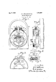
- Fig. 1 is a face view of an impulse starter embodying our improvement, the cover of the starter housing being removed and certain parts being in section;
- Fig. 2 is a vertical sectional vievv of the same, both Figs. 1 and 2 sho-Wing conventionally a portion of the magneto With vvhich the starter is adapted to vbe associated;
- FigfS is a vievv similar to Fig. 1, but showing only a portion of the impulse starter with the catch held in inoperative position;
- Fig. 4 is a sectional view substantially along the line 4-4 of Fig. 1, looking in the direction indicated bythe .arrows'; andFig. 5 shows the catch and locking bar in a slightly modifiedform.
- any suitable magneto may be employed With'the-i'mpulse starter, the magneto being indicated at 10 in Figs. 1 and 2.1 '
- the impulse starter with the exception lof the catch lock may have any suitable construction, but in this case it is of the type illustrated in the Karkau Patent No. 1,264,- O86, vgranted April 23, 1918, that is to say, Ythe impulse starter includes an inner part .11 which is xed to themagneto. shaft, and
- an outer part 12 adapted to be coupled to the magneto drive shaft, and normally adapted to drive the inner part, and hence the magneto rotor through a coilspring 13 which is enclosed within one of the parts, and the ends of which are engaged by studs 1d and 15 on the two parts 11 and .12 respectively.
- the inner part 11 has shoulders 16 which are diametrically opposite each other, which shoulders are adapted to be engaged by a catch 17, pivoted at 18 on a base 19 of the housing ⁇ 20 ot the impulse starter, 'lVhen the catch engages one ot the shoulders the magneto rotor is held against movement while the drive shaft is turning, causing compression ot the spring 13 and when the catch 17 is knocked out of engagement with the shoulder 1G by one of two cams 21 on the-outer part 12, the spring 18 gives the rotor a forward impulse sumcient to cause a spark which will ignite the mixture in the engine.
- an endwise movable locking bar 22 which at its lower end-is pivot-ally connected to the catch about midway between its ends as shown at 23, and extends upwardly through a slot at the top of the housing 20 and through a so-called spring holder 24 and a spring housing 25 which is secured by screws or equivalent means 26 to the top of' the main housing 20.
- the locking bar 22 On opposite edges of the locking bar 22 are two il-shaped protuberances 27, the lowersides of these protuberances being inclined inwardly more abruptly than the upper sides, and in the spring Aholder 24 are two small rollers 28 which are pressed'inwardly in a yielding manner against opposite edges of the locking bar 22, by coil springs 29 which are between the rollers and the ends ot the spring holder 24C.
- the construction is such that if the catch 17 is knocked out of engagement with the shoulder ⁇ 16 with only moderate torce, as when the engine is being cranked, the t-shaped protuberances will by their engagement with the rollers 28 elevate the spring holder 2-1 and will partially spread the rollers, in which event the catch will again drop back into engagement with the shouldered part of the impulse starter, so that the spark producing action will be repeated as desired, but when the engine starts, the catch will be thrown outwardly with rsuiiicient torce to cause the points or widest parts of the lV- shaped portuberances 27 to pass the rollers 28, in which event the rollers then snap inward under the protuberances 27 and effectively hold the bar 22 and the catch 17 in inoperative position, illustrated in Fig. 3, and no amount of vibration can release the catch. ln fact, the catch is securely held in inoperative position until the bar #is Aslot manually pushed downward and the points ot the V-shaped protuberance
- a driving part and a driven part adapted to be connected to the magneto, a catch for temporarily holding the driven part against movement and holding means therefor comprising a locking member' connected to the catch and a holding member mounted independently of the locking member past which the locking member moves and with which the locking member engages.
- an impulse starter for magnetos a driving part and a driven part, the latter adapted to be connected to the magneto, a catch for temporarily holding the driven part against movement, a locking member connected to the catch, and a spring actuated member engaging the locking member, the latter having a position determining part which the spring actuated member is adapted to engage.
- a driving part and a driven part adapted to be connected to the magneto, a catch for temporarily holding the driven part against movement, a locking member connected to the catch provided with an inclined positioning part,-and a detent adapted to engage it.
- a driving part and a driven part adapted to be connected to the magneto, a catch for temporarily holding the driven part against movement, ⁇ a locking member connected to the catch provided with a V- shaped protuberance, and a detent adapted to engage it.
- a driving part and a driven part adapted to be connected to the magneto, a catch. for temporarily holding the driven part against movement, a locking member for the catch provided with position determining parts, and detents on opposite sides of the locking member 6.
- a driving part and a driven part adapted to be connected to the magneto, a catch for temporarily holding the driven part against movement, a locking member for the catch having a pair of oppositely disposed V-shaped protuberances, and a pair of spaced' detents between which the locking member extends and adapted to ride up and down the inclined faces of the protuberances.
- a driving part and a driven part adapted to be connected to the magneto, a catch for temporarily holding the driven part against movement, a locking member connected to the catch, and a detent cooperating with the locking member, ,said detent having la limited movement in the direction of movement of the locking member.
- an. impulse starter for magnetos a driving part and a driven part, the latter adapted to be connected to the magneto, a catch. Jfor temporarily holding the driven part against movement, a housing enclosing the catch, a member for holding the catch in inoperative position and extending to the exterior of the housing, '.said member having its inner portion connected to the catch, and means engaging said member to hold the same in a position such thatthe catch is retained in inoperative position, said means permitting the catch to be thrown to operative vposition by inward ⁇ pressure o'n said member and by substantial-- ly endwise inward movement thereof.
- an impulse starter for magnetos a driving part and a driven part, the latter adapted to be connected to the magneto, a catch for temporarily holding the driven part against movement, a housing for holding the same, means for holding the catch in inoperative position.
- a holding member connected to the catch and extending out through said housing, said member moving outwardly in a substantially endwise direction when the catch is moved to inoperative position and being moved inwardly in a substantially endwise direction when the catch is moved to operative position.
Description
Jan, 6. 1925. 1,521,920
y J. A. WILLIAMS ET AL IMPULSE STARTER LOCK Filed Aug. 28, 1920 Paie-sea aan, e, was..
ai r i ori-fics.
JOSEPH A. WILLIAMS AND ALBERT G. KABKAU, OF CLEVELAND, O'HIO, ASSIGNORS 'T0 THE K-W IGNITION COMPANY, OF CLEVELAND, OHIO, A CORPORATION OIF OHIO.
IMPULSE-STARTER LOCK.
` Application inea August as, 1920. serial No. 406,588,
To all whom it may concern:
Be -it knovvn that We, JOSEPH A. l/VIL- LIAMs and ALBERT (ir. KARKAU, citizens of the United States, and residents, respectively, of Cleveland, in the county of Cuyahoga and State of Ohio, and Cleveland. in the county of Cuyahoga and State of Ohio, have invented a certain new and useful Improvement in Impulse-Starter Locks, of yWhich the following is a full, clear, and exact description.
This invention relates to impulse starters for magnetos, and especially to an improved form of lock for the'impulse starter catch.
Impulse starters commonly in use at the present time employ a pivoted catch which during normal operation is held in inoperative position, but for starting purposes is dropped inward to a position such that it may engage `a shoulder onV a memberv connected to the magneto rotor so as to hold the rotor against movement While the driving shaft is being turned through a portion of a revolution, after which a cam which turns With the drive shaft knocks the catch out of engagement With the, shoulder so as to permita 'spring to give the magneto armature a quick forward impulseso as to create a sparkl for starting purposes.
lt is customary also to provide a lock for the catch, the function of which is to hold the catch in inoperative position during normal operation. Frequently this lock is in the form of a pivoted finger so disposed that When the catch is thrown outwardly with predetermined force by the cam, a pointed or undercut part of the catchvvill snap over a pointed or tapered nose vof the locking finger and the latter Will then normally prevent its return to operative position until it is manually actuated so as to release the catch.'
While the 'form of lock above explained generally gives very good results, ,it has the objection that it is possible that the catch will not fully engage the locking finger, vin which event," due-to vibration it may fall into engagement With thel rapidly rotating shouldered partof the impulsevstarter beneath it, in which event breakage Will occur. Furthermore, in an impulse starter having a lock of this type, the catch falls by gravity when it is manually released, and at 4times it may not drop to operative position .have a film of oil causing a especially if the bearings of the catch should sticking tendency.
The principal object of the present invention is to provide alock which acts positively to hold the catch either in operative or in lnoperative position, and Which cannot posslbly hold' it inr an' .intermediate position from which it may be' moved by vibration in either direction; thatis to say, it is the principal object of the invention to provide-a lock of'a nature such that When the catch is throvvnouttvard by the cam on the rotating part ofthe impulse starter it cannot b e stopped and held in a position such that 1t can accidentally drop back to oper'- ative orvvorking position.
Still further the invention aims to provide a lock of such a nature that access can be had to it from the outside'o'f the housing to positively move the catch either to operaitive or inoperative position.
The invention may be briefly summarized l as consisting in certain novel details of construction, and combinations and arrangements of partsvvhich will be described in the specification and set-forth in the appended claims. A
' in the accompanying sheet of drawings,
Fig. 1 is a face view of an impulse starter embodying our improvement, the cover of the starter housing being removed and certain parts being in section; Fig. 2 is a vertical sectional vievv of the same, both Figs. 1 and 2 sho-Wing conventionally a portion of the magneto With vvhich the starter is adapted to vbe associated; FigfS is a vievv similar to Fig. 1, but showing only a portion of the impulse starter with the catch held in inoperative position; Fig. 4 is a sectional view substantially along the line 4-4 of Fig. 1, looking in the direction indicated bythe .arrows'; andFig. 5 shows the catch and locking bar in a slightly modifiedform.
'Any suitable magneto may be employed With'the-i'mpulse starter, the magneto being indicated at 10 in Figs. 1 and 2.1 'Likewise the impulse starter with the exception lof the catch lock may have any suitable construction, but in this case it is of the type illustrated in the Karkau Patent No. 1,264,- O86, vgranted April 23, 1918, that is to say, Ythe impulse starter includes an inner part .11 which is xed to themagneto. shaft, and
an outer part 12 adapted to be coupled to the magneto drive shaft, and normally adapted to drive the inner part, and hence the magneto rotor through a coilspring 13 which is enclosed within one of the parts, and the ends of which are engaged by studs 1d and 15 on the two parts 11 and .12 respectively. The inner part 11 has shoulders 16 which are diametrically opposite each other, which shoulders are adapted to be engaged by a catch 17, pivoted at 18 on a base 19 of the housing` 20 ot the impulse starter, 'lVhen the catch engages one ot the shoulders the magneto rotor is held against movement while the drive shaft is turning, causing compression ot the spring 13 and when the catch 17 is knocked out of engagement with the shoulder 1G by one of two cams 21 on the-outer part 12, the spring 18 gives the rotor a forward impulse sumcient to cause a spark which will ignite the mixture in the engine. Y .Y
In accordance with the present invention we employ an endwise movable locking bar 22 which at its lower end-is pivot-ally connected to the catch about midway between its ends as shown at 23, and extends upwardly through a slot at the top of the housing 20 and through a so-called spring holder 24 and a spring housing 25 which is secured by screws or equivalent means 26 to the top of' the main housing 20.
On opposite edges of the locking bar 22 are two il-shaped protuberances 27, the lowersides of these protuberances being inclined inwardly more abruptly than the upper sides, and in the spring Aholder 24 are two small rollers 28 which are pressed'inwardly in a yielding manner against opposite edges of the locking bar 22, by coil springs 29 which are between the rollers and the ends ot the spring holder 24C.
It will be seen, therefore, that the construction is such that if the catch 17 is knocked out of engagement with the shoulder `16 with only moderate torce, as when the engine is being cranked, the t-shaped protuberances will by their engagement with the rollers 28 elevate the spring holder 2-1 and will partially spread the rollers, in which event the catch will again drop back into engagement with the shouldered part of the impulse starter, so that the spark producing action will be repeated as desired, but when the engine starts, the catch will be thrown outwardly with rsuiiicient torce to cause the points or widest parts of the lV- shaped portuberances 27 to pass the rollers 28, in which event the rollers then snap inward under the protuberances 27 and effectively hold the bar 22 and the catch 17 in inoperative position, illustrated in Fig. 3, and no amount of vibration can release the catch. ln fact, the catch is securely held in inoperative position until the bar #is Aslot manually pushed downward and the points ot the V-shaped protuberances pass the rollers 28.
lWith this construction it is virtually impossible for the catch to be held in what may be termed the half-way position as has been possible with prior constructions as already stated, but should the upward movement of the locking bar by any chance stop with the rollers engaging the points of the protuberances 27, it would immediately be jarred loose from the shoulders when the spring holder 2d drops backlonto the housing so as to permit the catch to reengage the shoulder part ot the impulse starter before it has acquired any speed. lt is for that reason that the spring holder is mounted in the spring housing so that this small amount ci" lost motion is obtained. However, we do vnot regard this feature as essential, for the locking device is suficiently positive and certain in its action for all practical purposes with the spring holder lined iu position with reference to the housing.
rlhe advantage of having the locking bar and catch pushed downward by the action ot the springs as the rollers ride down the upper inclined faces o1 the il-shaped protuberances, is that the possibility ot the catch sticking as by a lilm ot oil, is entirely overcome. ln other words, the positive actuation by the springs ot the catch to operative position is more reliable than is the case if gravity alone is relied on Jfor this purpose.
ln Fig. 1 an ordinary pivotal connection is provided between the locking bar and the catch, but we may, if desired, provide a pin and slot connection between the locking bar andA catch as illustrated in Fig. 5, the bar here illustrated, designated 22a, having at its lower end a slightly elongated 22 instead oi a round hole 'for the connecting pin 23. V1With this construction the locking bar will maintain an absolute vertical position in the movement of the catch from its uppermost to its lowermost positions. This feature, however, is not essential, tor a suthciently ei'fective holding action is obtained by the protuberances 27 and rollersV with a straight pivotalA connection such as utilized in Fig. 1, even though this Causes a slight tilting of the locking bar.
lin the drawings we have illustrated the preferred construction wherein an endwise movable locking bar or nger is held positively in either its operative or inoperative position, and wherein the catch is' positively moved to operative position instead of permitted to drop to that position by gravity, but we do not desire to be confined to the construction shown, for the latter can be modified in many dilterent ways without deviating from the invention, as, for example, by the substitutionY of a single llll protuberance and a single holding roller for the two protuberances and two rollers herein illustrated, or by modifying the construction by the use of a roller or other equivalent detent to engage in notches of one or each side of the locking bar.
Having described our invention, claim:
l. In an impulse starter for magnetos, a driving part and a driven part, the latter adapted to be connected to the magneto, a catch for temporarily holding the driven part against movement and holding means therefor comprising a locking member' connected to the catch and a holding member mounted independently of the locking member past which the locking member moves and with which the locking member engages.
2. In an impulse starter for magnetos, a driving part and a driven part, the latter adapted to be connected to the magneto, a catch for temporarily holding the driven part against movement, a locking member connected to the catch, and a spring actuated member engaging the locking member, the latter having a position determining part which the spring actuated member is adapted to engage.
3. In an impulse starter for magnetos, a driving part and a driven part, the latter adapted to be connected to the magneto, a catch for temporarily holding the driven part against movement, a locking member connected to the catch provided with an inclined positioning part,-and a detent adapted to engage it.
4. In an impulse starter for magnetos, a driving part and a driven part, the latter adapted to be connected to the magneto, a catch for temporarily holding the driven part against movement,` a locking member connected to the catch provided with a V- shaped protuberance, and a detent adapted to engage it.
5. In an impulse starter for magnetos, a driving part and a driven part, the latter adapted to be connected to the magneto, a catch. for temporarily holding the driven part against movement, a locking member for the catch provided with position determining parts, and detents on opposite sides of the locking member 6. In an impulse starter for magnetos,
a driving part and a driven part, the latter adapted to be connected to the magneto, a catch for temporarily holding the driven part against movement, a locking member for the catch having a pair of oppositely disposed V-shaped protuberances, and a pair of spaced' detents between which the locking member extends and adapted to ride up and down the inclined faces of the protuberances.
7. In an impulse starter for magnetos, a driving part and a driven part, the latter adapted to be connected to the magneto, a catch for temporarily holding the driven part against movement, a locking member connected to the catch, and a detent cooperating with the locking member, ,said detent having la limited movement in the direction of movement of the locking member. i
8. In an. impulse starter for magnetos, a driving part and a driven part, the latter adapted to be connected to the magneto, a catch. Jfor temporarily holding the driven part against movement, a housing enclosing the catch, a member for holding the catch in inoperative position and extending to the exterior of the housing, '.said member having its inner portion connected to the catch, and means engaging said member to hold the same in a position such thatthe catch is retained in inoperative position, said means permitting the catch to be thrown to operative vposition by inward` pressure o'n said member and by substantial-- ly endwise inward movement thereof.
9. In an impulse starter for magnetos, a driving part and a driven part, the latter adapted to be connected to the magneto, a catch for temporarily holding the driven part against movement, a housing for holding the same, means for holding the catch in inoperative position. comprising a holding member connected to the catch and extending out through said housing, said member moving outwardly in a substantially endwise direction when the catch is moved to inoperative position and being moved inwardly in a substantially endwise direction when the catch is moved to operative position.
In testimony whereof, we hereunto affix our signatures.
JOSEPH A. WILLIAMS. ALBERT Gr. KARKAU,
Priority Applications (1)
| Application Number | Priority Date | Filing Date | Title |
|---|---|---|---|
| US406588A US1521920A (en) | 1920-08-28 | 1920-08-28 | Impulse-starter lock |
Applications Claiming Priority (1)
| Application Number | Priority Date | Filing Date | Title |
|---|---|---|---|
| US406588A US1521920A (en) | 1920-08-28 | 1920-08-28 | Impulse-starter lock |
Publications (1)
| Publication Number | Publication Date |
|---|---|
| US1521920A true US1521920A (en) | 1925-01-06 |
Family
ID=23608648
Family Applications (1)
| Application Number | Title | Priority Date | Filing Date |
|---|---|---|---|
| US406588A Expired - Lifetime US1521920A (en) | 1920-08-28 | 1920-08-28 | Impulse-starter lock |
Country Status (1)
| Country | Link |
|---|---|
| US (1) | US1521920A (en) |
-
1920
- 1920-08-28 US US406588A patent/US1521920A/en not_active Expired - Lifetime
Similar Documents
| Publication | Publication Date | Title |
|---|---|---|
| US1521920A (en) | Impulse-starter lock | |
| US2400216A (en) | Starting control circuit for engines | |
| US1556273A (en) | Daniel yeld wheatley | |
| US2747414A (en) | Starter | |
| GB390972A (en) | Improvements in or relating to starting gear for internal combustion engines | |
| US2373507A (en) | Starter for internal-combustion engines | |
| US1457462A (en) | Circuit beeakee fob ignition systems | |
| US1693342A (en) | Engine starter | |
| US1264086A (en) | Impulse-starter. | |
| US1623270A (en) | Magneto | |
| US1603766A (en) | Automobile starting switch | |
| US1328892A (en) | Starter applicable to magnetos | |
| US1332704A (en) | Spark-plug | |
| US2307207A (en) | Engine starter | |
| US2219672A (en) | Starting device | |
| US2093965A (en) | Motor starting crank safety device | |
| US1466926A (en) | Engine starter | |
| US2430057A (en) | Magneto | |
| US1331697A (en) | Safety-starter | |
| US1898423A (en) | Engine starter | |
| GB755594A (en) | Improvements in or relating to engine starter drives | |
| US1356876A (en) | Starting-crank | |
| US1303469A (en) | Ignition-generatob | |
| US1590759A (en) | Engine starter | |
| US2012264A (en) | Engine starter drive |