US1516339A - Furnace and method of controlling the draft therein - Google Patents
Furnace and method of controlling the draft therein Download PDFInfo
- Publication number
- US1516339A US1516339A US477055A US47705521A US1516339A US 1516339 A US1516339 A US 1516339A US 477055 A US477055 A US 477055A US 47705521 A US47705521 A US 47705521A US 1516339 A US1516339 A US 1516339A
- Authority
- US
- United States
- Prior art keywords
- draft
- pressure
- fuel
- grate
- valve
- Prior art date
- Legal status (The legal status is an assumption and is not a legal conclusion. Google has not performed a legal analysis and makes no representation as to the accuracy of the status listed.)
- Expired - Lifetime
Links
Images


Classifications
-
- F—MECHANICAL ENGINEERING; LIGHTING; HEATING; WEAPONS; BLASTING
- F23—COMBUSTION APPARATUS; COMBUSTION PROCESSES
- F23H—GRATES; CLEANING OR RAKING GRATES
- F23H11/00—Travelling-grates
- F23H11/10—Travelling-grates with special provision for supply of air from below and for controlling air supply
Definitions
- This invention relates to improvements in furnaces and methods of controlling the draft therein, and the novel features of the invention are adapted for use in a furnace
- the object of the invention is to regulate or control the How of draft through openings in the bed of fuel supported on the grate.
- the draft pressure below the grate is reduced by the free escape of draft through an opening in the fuel, and in the preferredd form of the invention I take advantage of this reduction to determine the location of the opening. I then prevent a rapid delivery of draft through the opening. After the location of the opening has been determined, the draft can be retarded or otherwise prevented from escaping freely through the openinga Assuming that a blower, or other suitablev blast device, is used to maintain an'approximately constant normal pressure under a portion of the grate, when an openin'g appears in the fuel above this portion of the grate a rapid escape of draft at the opening will result in a reduction in the pressure.
- the herein scribed method r. consists in reducing the draft at the portion of the fuel in which an opening is formed, without changing the draft at other portions of the fuel. I will hereafter point out how this is accomplished in a bed of fuel supported by a traveling grate.
- Fig. I is a side elevation of a furnace equipped with a draft regulating means embodying the features of this invention, a portion of the furnace wall being broken away to show the chain grate.
- Fig. II is an enlarged fgmentary side elevation, partly in sectiomshowing one of the draft regulating devices.
- Fig. III vis a vertical section taken approximately through the middle of Fig. II, the middle portion of the furnace structure being broken away.
- Fig. IV is an enlarged section of one of the valve operating devices.
- Fig. V is a section on the line V-V in Fig. IV.
- Fig. VI isa section on the line VI-VI in Fig. IV. f
- FIG. I Shown ya mechanical Stoker comprising an endless chain grate A supported between side frame members 1.
- the chain grate comprises many grate links 3 connected by means of pivot rods 4 arranged transversely of the ate.
- a power shaft 5 (Fig. I), supported by the side frames 1, is provided with any desired number of sprocket wheels 6 for transmitting movement to the-endless chain grate.
- the chain grate passes around the sprocket wheels 6 and also around a plain idle wheel, or roll 7 ,the latter being mounted on a shaft 8.
- rIhe fuel passes from a hopper 9 to the top face of the grate, as indicated by arrows in Fig. I.
- the furnace is provided with suitable side walls B, located adjacent to the side margins of the grate.
- 12 designates draft boxes surrounded by the traveling grate and extending from a side frame 1 at one side of the grate to the frame 1 at the other side. All of these draft boxes are open at ⁇ the top to provide for the delivery of draft to the grate.
- the several draft boxes 12 are located adjacent to eachother, as shown by Fig. I, and the fuel-supporting portion of the grate travels over their upper edges.
- Each draft box 12 may be provided at one end with an intake nipple 13 (Fig. III) telescoping with a nipple la in one of the furnace walls B.
- I have shown a series of individual turbines or rotary engines 15 each associated with one of the draft boxes 12, as shown by Figs. I and III, and each supported by a tubular member 16 telescoping with one of the nipples 14.
- -Each engine, or turbine, 15 is provided with a rotary fan 17 located in a tubular member 16.
- Fluid under pressure preferably steam
- a valve 18 in the main supply pipe (Fig. I) may be adjusted to simultaneously regulate all of the turbines.
- one of the regulating valves 20 is adjusted to reduce the draft pressure in the bo'x below the opening, the valve 20 being selected to reduce the speed of the turbine associated with the individual draft box below the opening. It will be apparent that this involves the problem of determining where the opening is located and thereafter selecting the particular val v'e 2O associated with the draft producing means for 'the particular draft box below the opening.
- Each valve 2O is equipped with an operating lever 21 fulcrumed at 22 and connected to a valve operating stem 23.
- the means for actuating the levers 21 includes piston rods 24 connected to the respective levers, each rod 24 (Fig. IV) being fixed to a piston.25 mounted in a cylinder 26.
- They several pistons are operated by means of Huid under pressure, such as compressed air, transmitted through a supply pipe 27 having branches 28 leading to the several cylinders 26.
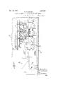
- eachcylinder l26 is provided with an intake passageway 29 leading from the pressure supply pipe 28 to points near the ends of a valve 30, said valve having an operating stem 31 provided with an operating arm 32 whereby the valve is rocked to control the admission andl discharge of fluid. Passag'eways 33 and 34 lead-from the end por- When the valve 30 occupies the position shown by Figs. IV, V and VI, the pressure supply pipe 28 and the intake passageway 29 are in free communication withthe valve passageway 36 and the passageway 34 leading to the right hand end of the cylinder;
- Figs. IV and V show that the valve passageway 35 is in communication with the passageways 33 and 33 leading from the left hand end of the cylinder to provide for the discharge of fluid through the exhaust y port 33a.
- valve 30 If the valve 30 is turned about one quarter of a revolution from the position shown by Figs. IV, V and VI, the conditions just pointed out will be reversed. Fluid will then be permitted to ow from the supply pipe 28, through passageways 35 and 33 to the left hand end of the cylinder, so as to force the piston 25 and the rod 24 to the right from the position shown in Fig. IV ⁇ and at the same time the valve port 36 will be so located that the fluid displaced from tue right hand side of the piston will be permitted to pass outthrough the passageways 34 and 34', 36 and 34a.
- Any other suitable means could be used to control the admission and discharge of Huid at the cylinder 26, the object being to produce a simple means for transmitting motion to any selected valve operating lever 21. and the desired result can'be accomplished by merely rocking the valve 30 at the cylinder 26 so as totransmit fluid presassociated with said edraft box is adjusted to reduce the speed of the turbine for this particular draft box, thereby reducing the draft below the opening in the fuel.
- the automatic means for selecting and regulating the valves 20 preferably includes pressure-responsive devices controlling the delivery of fluid under pressure to the cylinders 26, whereby the piston rods 24 and levers 21 are actuated to regulatesaid valves 20.
- pressure-responsive devices controlling the delivery of fluid under pressure to the cylinders 26, whereby the piston rods 24 and levers 21 are actuated to regulatesaid valves 20.
- y- II 'contains a partition 41 whereby it is divided into a pressure compartment 42 and l to a point near the bottom wall thereof tov a float. compartment 43.
- the partition 41 extends from the top wall of the chamber 40 provide for the flow of liquid 44 from one compartment to the other.
- a float 45 (Fig.--
- each pressure compartment 42 is thus associated with one ofl the draft boxes, and the liquid level in the compartment 42 will rise and fall in response to the variations of the draft pressure the draft box.
- Each pressure compartment 42 is therefore normally under pressure, so the liquid level of the compartment 42 will be lower tha-n that of the'loat compartment 43.
- each float 45 (Fig. II) will normally occupy its elevated position to retain the adjacent valve-operatingy arm 32 and its valve 30 in the positions shown by Figs. II, IV, V and VI.
- 'Ihe piston 25 is therefore normally retained at the left hand end of the cylinder, as shown by Fig. IV, and the valve operating lever 21 is normally retained in the position shown by Fig. II, so as to permit free passage of steam through the regulating valve 20.
- rIhe operations may be briey described as follows: Y
- This automatic selection and regulation of the draft producing devices may be accomplished as a result of variations in the pressure of the draft itself, and although the draft pressure is not very great, any desired degree of power can be obtained for the automatic adjustment of v the apparatus.
- the draft pressure acts upon a very sensitive device comprising the pressure 'chambers 40 each containing a body of liquid having a ⁇ large surface area exposed to the draft pressure, and each containing a float adapted to readily move in response to variations in the liquid level.
- the float merely actu-- ates a readily movable valve 30 to control the delivery of compressed air to an operating device from which an almost unlimited degree of power couldbe obtained to actuate the regulating device'.
- a further advantage of the invention herein disclosed lies in the fact that the several draft boxes direct the draft to different portions of thefuel, and whenever an opening appears in one of these portions,
- the draft is reduced at this particular portion of the fuel without in any way affect- ⁇ ing the draft at the other draft boxes, and this result is accomplished throughout the apparatus as the fuel travels from one draft box to another.
- the method of controlling the delivery ofldraft through an opening in a fuel bed which consists in transmitting draft from ⁇ separate independent sources to successive portions of the fuel bed, moving the fuel bed to successively place the open portion of the fuel in communication with said sources, and utilizing ⁇ the pressures at said separate portions of the fuel bed to successively regulate the flow of draft from said separate sources so as to maintain a reducedl flow of v draft at the open portion of the fuel.
- a furnace provided with a fuel-supporting grate, and means for regulating the flow of draft to openings in the fuel on said grate, said means including a series ofautomatic draft controllers responsive to vdraft pressures below different portions of the grate.
- a furnace provided with a fuel-supporting grate, and means for regulating the flow of draft through openings in the fuel on said grate, said means including a series of draft-ducts between the grate and the source ofthe draft, said draft-ducts being located below and transversely of the bottom of said grate, and automatic regulating ieans controlling the draft in said draftucts.
- a furnace provided with a fuel-supl ⁇ porting grate, and means for regulating the flow of draft through openings in the fuel on said grate, said means including a series lof draft-ducts between the grate and the with one of said ducts to automatically regulate the delivery of draft therefrom.
- a furnace provided with a traveling fuel-supporting grate,' and means for regulating the flow of draft through openings in the fuel on said traveling grate, said means including a succession of draft-ducts located between the traveling grate and the source of the draft, and a succession of automatic draft controllers for regulating the flow of draft from said ducts, ⁇ each of said draft controllers being responsive to variations of the draft pressure in one of said ducts.
- a furnace provided With a traveling fuel-supporting grate, and means for regulating the flow of draft through openings in the fuel on said traveling grate, said means including a succession of draft-ducts below and adjacent to the fuel-supporting portion of said traveling grate, and independently operable draft controllers for the respective draft ducts, each of said draft controllers being associated With one of said ducts and responsive to variations of the draft'pressure therein.
- a furnace provided with an endless traveling fuel-supporting grate, draft boxes arranged transversely of and surrounded by said endless traveling grate, said draft boxes' being open at the top to provide for the delivery of draft through the upper portion of said endless traveling grate, and means for controlling the flow of draft through openings in the fuel supported on said traveling grate, said means including a separate draft regulator for each draft box, and pressureresponsive means controlling the draft regulators, said pressure-responsive means being in communication With the respective draft boxes and under the control of the draft pressure therein.
- a furnace provided With an endless traveling fuel-supporting grate, draft boxes arranged transversely of and surrounded by responsive controlling devices each associated With one of said draft boxes and one of said regulating devices, each pressureresponsive controlling device being in communication With one of said draft boxes and provided with an operating member for one of said individual regulating devices.
- a furnace provided With an endless traveling fuel-supporting grate, draft boxes arranged transversely of and surrounded by said endless traveling grate, said draft boxes being open at the top to provide for the delivery of draft throughithe upper portion of said endless traveling grate, an individual fan for each of said draft boxes, an individual fluid-actuated motor for each 0f said fans, an individual regulating valve for each motor, an individual operating device for each valve', and an individual pressureresponsive controlling device for each operating device, each of said pressure responsivecontrolling devices being in communication with one of the draft boxes and movable in response to ⁇ variations in the draft pressure therein.
Landscapes
- Engineering & Computer Science (AREA)
- Chemical & Material Sciences (AREA)
- Combustion & Propulsion (AREA)
- Mechanical Engineering (AREA)
- General Engineering & Computer Science (AREA)
- Control Of Steam Boilers And Waste-Gas Boilers (AREA)
Description
W. M. DUNCAN FURNACE AND METHOD oF coNTRoLLING' THD DRAFT THEREIN Filed 'June 13,
19?.) 3 Shets--Shee l Nom H8 1924.
W. M. DUNCAN FURNAGE` AND METHOD OF CONTROLLING THE DRAFT THEREIN Filed June 13 1921 5 Sheets-'Sh'eevt 2 Nov. la, 1924, 1,516,339 y W. M. DUNCAN FURNACE AND METHOD OF' CvONTROLLING THE DRAFT THEREIN Filed June 13 1921 3 Sheets-'Sheet 5 Patented Nov. 18,
' provided with a traveling grate.
vov
UNITED STATES 1,516,339 PATENT OFFICE.
WILLIAM DUNCAN, 0F ALTON, ILLINOIS.
FURNACE AND METHOD 0F CONTOLLING THE DRAFT THEREIN.
Application led June 13, 1921. Serial No. 477,055.
To all whom it may concern:
Be it known that I, WILLIAM M. DUNCAN, a citizen ofthe United States ,of America, and a resident of Alton, in the county of Madison and State of Illinois, have invented certain new and useful Improvements in Furnaces .and Methods of Controlling the Draft Therein, of which the following is a full, clear, and exact description, reference being had to the accompanying drawings, forming a part of this specification.
This invention relates to improvements in furnaces and methods of controlling the draft therein, and the novel features of the invention are adapted for use in a furnace The object of the invention is to regulate or control the How of draft through openings in the bed of fuel supported on the grate.
It `is difficult to maintain a uniform bed of fuel on a grate, and this is especially true in a furnace provided with a travelinggrate. Actual experience has shown that openings are frequently formed in the fuel bed on a traveling grate, and the forced draft is then permitted to freely escape through'the openings. The efliciency of the draft is thus greatly reduced by the free .escape of forced draft through an opening in the fuel which chills the combustible gases in the combustion chamber, and the opening is gradually enlarged by rapid combustion resulting gr from the draft at this point.
The draft pressure below the grate is reduced by the free escape of draft through an opening in the fuel, and in the preferredd form of the invention I take advantage of this reduction to determine the location of the opening. I then prevent a rapid delivery of draft through the opening. After the location of the opening has been determined, the draft can be retarded or otherwise prevented from escaping freely through the openinga Assuming that a blower, or other suitablev blast device, is used to maintain an'approximately constant normal pressure under a portion of the grate, when an openin'g appears in the fuel above this portion of the grate a rapid escape of draft at the opening will result in a reduction in the pressure. When this occurs, I Preferably effect a still greater reduction o the pressure at that portion of the grate, thereby preventing delivery of excess draft through the opening. ,More speclfically stated, the herein scribed method r.consists in reducing the draft at the portion of the fuel in which an opening is formed, without changing the draft at other portions of the fuel. I will hereafter point out how this is accomplished in a bed of fuel supported by a traveling grate.
Fig. I is a side elevation of a furnace equipped with a draft regulating means embodying the features of this invention, a portion of the furnace wall being broken away to show the chain grate.
Fig. II is an enlarged fgmentary side elevation, partly in sectiomshowing one of the draft regulating devices.
Fig. III vis a vertical section taken approximately through the middle of Fig. II, the middle portion of the furnace structure being broken away. n
Fig. IV is an enlarged section of one of the valve operating devices.
Fig. V is a section on the line V-V in Fig. IV.
Fig. VI isa section on the line VI-VI in Fig. IV. f
To illustrate the invention, I have Shown ya mechanical Stoker comprising an endless chain grate A supported between side frame members 1. The chain grate comprises many grate links 3 connected by means of pivot rods 4 arranged transversely of the ate. A power shaft 5 (Fig. I), supported by the side frames 1, is provided with any desired number of sprocket wheels 6 for transmitting movement to the-endless chain grate. The chain grate passes around the sprocket wheels 6 and also around a plain idle wheel, or roll 7 ,the latter being mounted on a shaft 8. rIhe fuel passes from a hopper 9 to the top face of the grate, as indicated by arrows in Fig. I.
The furnace is provided with suitable side walls B, located adjacent to the side margins of the grate. 12 designates draft boxes surrounded by the traveling grate and extending from a side frame 1 at one side of the grate to the frame 1 at the other side. All of these draft boxes are open at `the top to provide for the delivery of draft to the grate. The several draft boxes 12 are located adjacent to eachother, as shown by Fig. I, and the fuel-supporting portion of the grate travels over their upper edges.
Each draft box 12 may be provided at one end with an intake nipple 13 (Fig. III) telescoping with a nipple la in one of the furnace walls B. As an illustration of a suitable means for creating a forced draft. I have shown a series of individual turbines or rotary engines 15 each associated with one of the draft boxes 12, as shown by Figs. I and III, and each supported by a tubular member 16 telescoping with one of the nipples 14. -Each engine, or turbine, 15 is provided with a rotary fan 17 located in a tubular member 16. When one of the turbines is operated, its fan is rotated to create a forced draft in one of the draft boxes 12. Since there is-a separate turbine and fan for each draft box, it will be noted that the draft in any one of the draft boxes can be regulated without varying the draft in the other draft boxes.
Fluid under pressure, preferably steam,
is delivered tothe several turbines through the medium of a main supply pipe 18 having branches 19 leading to the respective turbines. Each branch 19 is provided with -a regulating valve 20, so the turbines can be regulated independently of each other for the purpose of varying the draft in any selected draft box without changing the draft pressure in the other draft boxes. A valve 18 in the main supply pipe (Fig. I) may be adjusted to simultaneously regulate all of the turbines.
When an opening is formed in the traveling bed of fuel, one of the regulating valves 20 is adjusted to reduce the draft pressure in the bo'x below the opening, the valve 20 being selected to reduce the speed of the turbine associated with the individual draft box below the opening. It will be apparent that this involves the problem of determining where the opening is located and thereafter selecting the particular val v'e 2O associated with the draft producing means for 'the particular draft box below the opening.
I will now describe a means whereby all of this can be riutomatically accomplished.
Each valve 2O is equipped with an operating lever 21 fulcrumed at 22 and connected to a valve operating stem 23. The means for actuating the levers 21 includes piston rods 24 connected to the respective levers, each rod 24 (Fig. IV) being fixed to a piston.25 mounted in a cylinder 26. They several pistons are operated by means of Huid under pressure, such as compressed air, transmitted through a supply pipe 27 having branches 28 leading to the several cylinders 26.
As shown most clearly by Figs. IV, V and VI, eachcylinder l26 is provided with an intake passageway 29 leading from the pressure supply pipe 28 to points near the ends of a valve 30, said valve having an operating stem 31 provided with an operating arm 32 whereby the valve is rocked to control the admission andl discharge of fluid. Passag'eways 33 and 34 lead-from the end por- When the valve 30 occupies the position shown by Figs. IV, V and VI, the pressure supply pipe 28 and the intake passageway 29 are in free communication withthe valve passageway 36 and the passageway 34 leading to the right hand end of the cylinder;
The piston 25 is therefore subjected to the fluid pressure transmitted through these passageways. At this time, the fluid pressure cannot be transmitted through the valve passageway 35 for the reason thatthis passageway is not in communication with the inlet passageway 29. This is illustrated by Figs. IV and V, which show that the valve passageway 35 is in communication with the passageways 33 and 33 leading from the left hand end of the cylinder to provide for the discharge of fluid through the exhaust y port 33a.
If the valve 30 is turned about one quarter of a revolution from the position shown by Figs. IV, V and VI, the conditions just pointed out will be reversed. Fluid will then be permitted to ow from the supply pipe 28, through passageways 35 and 33 to the left hand end of the cylinder, so as to force the piston 25 and the rod 24 to the right from the position shown in Fig. IV` and at the same time the valve port 36 will be so located that the fluid displaced from tue right hand side of the piston will be permitted to pass outthrough the passageways 34 and 34', 36 and 34a..
Any other suitable means could be used to control the admission and discharge of Huid at the cylinder 26, the object being to produce a simple means for transmitting motion to any selected valve operating lever 21. and the desired result can'be accomplished by merely rocking the valve 30 at the cylinder 26 so as totransmit fluid presassociated with said edraft box is adjusted to reduce the speed of the turbine for this particular draft box, thereby reducing the draft below the opening in the fuel.
The automatic means for selecting and regulating the valves 20 preferably includes pressure-responsive devices controlling the delivery of fluid under pressure to the cylinders 26, whereby the piston rods 24 and levers 21 are actuated to regulatesaid valves 20. As an illustration of this vfeature of the invention I have shown a series of pressure chambers 40 each of which is associated with one of the draftboxes 12 and also with one of the cylinders 26, as will be presently described. Each pressure chamber 40 (Fig.v
y- II) 'contains a partition 41 whereby it is divided into a pressure compartment 42 and l to a point near the bottom wall thereof tov a float. compartment 43. The partition 41 extends from the top wall of the chamber 40 provide for the flow of liquid 44 from one compartment to the other. A float 45 (Fig.-
II) is located in the float compartment 43 and connected to a valve operating arm 32 by means of -a rod 46. 47- designates pressure pipes leading from the interior of draft boxes l2 to the upper portions of the respective pressure chambers 40, each pipe 47 being in free communication with the upper end of a pressure compartment 42, as shown by Fig. II, and the pressure compartment being otherwise closed above the liquid therein, so the liquid will be subjected to the draft pressure in the draft box. Each pressure compartment 42 is thus associated with one ofl the draft boxes, and the liquid level in the compartment 42 will rise and fall in response to the variations of the draft pressure the draft box. Each pressure compartment 42 is therefore normally under pressure, so the liquid level of the compartment 42 will be lower tha-n that of the'loat compartment 43. A s a consequence, each float 45 (Fig. II) will normally occupy its elevated position to retain the adjacent valve-operatingy arm 32 and its valve 30 in the positions shown by Figs. II, IV, V and VI. 'Ihe piston 25 is therefore normally retained at the left hand end of the cylinder, as shown by Fig. IV, and the valve operating lever 21 is normally retained in the position shown by Fig. II, so as to permit free passage of steam through the regulating valve 20.
When the pressure in a compartment 42 (Fig. II) is decreased to a degree materially below the normal pressure, the liquid will rise in compartment 42 and the adjacent float k45 will fall in the compartment 43 so as to transmit motion to the valve operating arm 32 to which the float is connected. If the 4drop in pressure is great enough, the dispiston 25, with the result of. moving the piston rod 24 and lever 21 to the right froml the positions shown by Fig. II, thereby partly closing the regulating valve 20 to decrease the speed of the turbine lassociated with said valve. Thereafter, when the pres# sure in compartment 42 is increased, the float 45 will rise in the float compartment 43 to restore the valve 30 tothe position shown by Figs. IV, V and VI.
rIhe operations may be briey described as follows: Y
Under normal operating, conditions, all of the turbine-regulating valves 2O are wide open, and all of the turbines and their draft producing fans are then operated at the normal speeds. A. predetermined normal draft pressure is thus maintained in each draft box 12 below the fuel-supporting portion of the gra-te. Of course, the pressure will not be maintained precisely at any predetermined degree, for even under the normal conditions there will be some slight variations resulting from slight variations in the fuel bed, but this will not materially affect the automatic pressure-responsive device. However, when there is an opening in the fuel bed at a point above one of the draft boxes, the draft will freely and quickly escape through this opening so as to reduce the draft pressure in this particular draft box, and there willbe a corresponding reduction of the pressure in the pressure compartment 42 (Fig. II) communicating with said draft box. As a consequence, the liquid will rise in this particular compartment 42 and fall in the adjacent float compartment 43. rIhe float 4 5 will then move downwardly to actuate the valve 3() (Fig. IV) to which it is connected. When this occurs, the valve 30 will be turned about one quarter of a revolution from the position shown by Figs. IV, V Vand VI, and the piston 25 will be actuatedl to partly close the particular valve 20 associated with the pressure compartment 42 and draft box 12 to which I have just referred.
It will now be understood that when an opening appears in the fuel above a draft box, the draft pressure in this box will be decreased as a result of 'theffree outlet, or vent, formed by the opening, and immediately thereafter the speed, of the draft rapid Lescape of draft through the opening which would chill the combustible gases in the combustion chamber and at the same time enlarge the opening by rapid combustion of the fuel around the opening.
Assuming now that there is an opening in the fuel above one of the draft boxes, and that' the draft pressure hasbeen decreased below the opening, as just pointed out. The
fuel is supported by a traveling grate, so the portion of thefuel in which the opening is formed will slowly move to a point over the next adjacent draft box, and then on over the other draft boxes. Whenever this open portion of the fuel is`located over one of the draft boxes. the draft pressure below the opening )will be reduced by one of the automatic pressure-responsive controlling devices, as previously pointed out. Although the pressure in each successive draft box isreduced when an open portion of the fuel is located above the same, the normal pressure should be restored when the open portion of the fuel passes away from the draft box. This is accomplished as follows:
It is to be understood that all of the turbines are driven constantly, although the speed of a turbine is reduced when an opening appears in the fuel above the draft box to which the turbine is connected. Therefore, when an'open portion of the fuel passes away from a draft box, the pressure in this draft box is gradually increased for the reason that there is no large open draft outlet in the fuel above the draft box, and as the draft pressure increases in the draft box there will be a corresponding increase-of pressure in the pipe 47 and pressure chambe'r 40 communicating with said draft box. Owing to this increase of pressure in the pressure compartment 42v (Fig. II) the adjacent float 45 will be elevated to restore the float actuated valve 30 to the position shown by Figs. IV, V and VI, thereby restoring the piston 25, piston rod 24 and valve-operating lever 21 to permit free delivery of the steam through the regulating valve 20 controlled by the float.
This automatic selection and regulation of the draft producing devices may be accomplished as a result of variations in the pressure of the draft itself, and although the draft pressure is not very great, any desired degree of power can be obtained for the automatic adjustment of v the apparatus. The draft pressure acts upon a very sensitive device comprising the pressure 'chambers 40 each containing a body of liquid having a` large surface area exposed to the draft pressure, and each containing a float adapted to readily move in response to variations in the liquid level. However, the float merely actu-- ates a readily movable valve 30 to control the delivery of compressed air to an operating device from which an almost unlimited degree of power couldbe obtained to actuate the regulating device'.
A further advantage of the invention herein disclosed lies in the fact that the several draft boxes direct the draft to different portions of thefuel, and whenever an opening appears in one of these portions,
the draft is reduced at this particular portion of the fuel without in any way affect-` ing the draft at the other draft boxes, and this result is accomplished throughout the apparatus as the fuel travels from one draft box to another.
I claim.
1. The method of transmitting and controlling draft in a traveling bed of fuel soy as to reduce the flow of draft through any maintain a reduced draft pressure below saidA opening, and at the same time maintaining a higher draft pressure below other portions of the traveling fuel bed.
.2. The method of controlling the delivery ofldraft through an opening in a fuel bed which consists in transmitting draft from` separate independent sources to successive portions of the fuel bed, moving the fuel bed to successively place the open portion of the fuel in communication with said sources, and utilizing `the pressures at said separate portions of the fuel bed to successively regulate the flow of draft from said separate sources so as to maintain a reducedl flow of v draft at the open portion of the fuel.
' 3. A furnace provided with a fuel-supporting grate, and means for regulating the flow of draft to openings in the fuel on said grate, said means including a series ofautomatic draft controllers responsive to vdraft pressures below different portions of the grate.
4. A furnace provided with a fuel-supporting grate, and means for regulating the flow of draft through openings in the fuel on said grate, said means including a series of draft-ducts between the grate and the source ofthe draft, said draft-ducts being located below and transversely of the bottom of said grate, and automatic regulating ieans controlling the draft in said draftucts.
5. A furnace provided with a fuel-supl `porting grate, and means for regulating the flow of draft through openings in the fuel on said grate, said means including a series lof draft-ducts between the grate and the with one of said ducts to automatically regulate the delivery of draft therefrom.
`6. A furnace provided with a traveling fuel-supporting grate,' and means for regulating the flow of draft through openings in the fuel on said traveling grate, said means including a succession of draft-ducts located between the traveling grate and the source of the draft, and a succession of automatic draft controllers for regulating the flow of draft from said ducts, `each of said draft controllers being responsive to variations of the draft pressure in one of said ducts.
7. A furnace provided With a traveling fuel-supporting grate, and means for regulating the flow of draft through openings in the fuel on said traveling grate, said means including a succession of draft-ducts below and adjacent to the fuel-supporting portion of said traveling grate, and independently operable draft controllers for the respective draft ducts, each of said draft controllers being associated With one of said ducts and responsive to variations of the draft'pressure therein.
8. A furnace provided with an endless traveling fuel-supporting grate, draft boxes arranged transversely of and surrounded by said endless traveling grate, said draft boxes' being open at the top to provide for the delivery of draft through the upper portion of said endless traveling grate, and means for controlling the flow of draft through openings in the fuel supported on said traveling grate, said means including a separate draft regulator for each draft box, and pressureresponsive means controlling the draft regulators, said pressure-responsive means being in communication With the respective draft boxes and under the control of the draft pressure therein.
9. A furnace provided With an endless traveling fuel-supporting grate, draft boxes arranged transversely of and surrounded by responsive controlling devices each associated With one of said draft boxes and one of said regulating devices, each pressureresponsive controlling device being in communication With one of said draft boxes and provided with an operating member for one of said individual regulating devices.
10. A furnace provided With an endless traveling fuel-supporting grate, draft boxes arranged transversely of and surrounded by said endless traveling grate, said draft boxes being open at the top to provide for the delivery of draft throughithe upper portion of said endless traveling grate, an individual fan for each of said draft boxes, an individual fluid-actuated motor for each 0f said fans, an individual regulating valve for each motor, an individual operating device for each valve', and an individual pressureresponsive controlling device for each operating device, each of said pressure responsivecontrolling devices being in communication with one of the draft boxes and movable in response to` variations in the draft pressure therein.
In testimony that I claim the foregoing I hereunto aix my signature.
WILLIAM M. DUNCAN.
Priority Applications (1)
| Application Number | Priority Date | Filing Date | Title |
|---|---|---|---|
| US477055A US1516339A (en) | 1921-06-13 | 1921-06-13 | Furnace and method of controlling the draft therein |
Applications Claiming Priority (1)
| Application Number | Priority Date | Filing Date | Title |
|---|---|---|---|
| US477055A US1516339A (en) | 1921-06-13 | 1921-06-13 | Furnace and method of controlling the draft therein |
Publications (1)
| Publication Number | Publication Date |
|---|---|
| US1516339A true US1516339A (en) | 1924-11-18 |
Family
ID=23894325
Family Applications (1)
| Application Number | Title | Priority Date | Filing Date |
|---|---|---|---|
| US477055A Expired - Lifetime US1516339A (en) | 1921-06-13 | 1921-06-13 | Furnace and method of controlling the draft therein |
Country Status (1)
| Country | Link |
|---|---|
| US (1) | US1516339A (en) |
-
1921
- 1921-06-13 US US477055A patent/US1516339A/en not_active Expired - Lifetime
Similar Documents
| Publication | Publication Date | Title |
|---|---|---|
| US1516339A (en) | Furnace and method of controlling the draft therein | |
| US1341319A (en) | Automatic valve-regulator | |
| US1296040A (en) | Locomotive draft apparatus. | |
| US1522877A (en) | Furnace regulation | |
| US1338922A (en) | Regulating combustion-furnaces | |
| US1783358A (en) | Automatic temperature control in pulverizing mills | |
| US2421861A (en) | Control apparatus | |
| US1388030A (en) | Pulverized-fuel-burning apparatus | |
| US1540607A (en) | Apparatus for controlling the combustion of fuel | |
| US868358A (en) | Controlling apparatus for heat-engines. | |
| US289481A (en) | w wilcox | |
| US1565858A (en) | Method of and apparatus for controlling back pressure and draft in locomotives | |
| US1281316A (en) | Control apparatus for steam-boilers, &c. | |
| US1208432A (en) | Draft-regulator. | |
| US324061A (en) | woodbury | |
| US510584A (en) | Furnace | |
| US1516414A (en) | Damper-operating device | |
| US2659324A (en) | Combustion control system | |
| US1817219A (en) | Control means for hot blast stoves | |
| US821268A (en) | Smoke-consuming furnace. | |
| US715919A (en) | Draft and damper regulator for furnaces. | |
| US742128A (en) | Automatic forced-draft regulator. | |
| US999426A (en) | Gas-engine. | |
| US2025629A (en) | Method of and apparatus for controlling marine boilers | |
| US1034673A (en) | Gas-engine. |