US1516060A - Amplifier - Google Patents
Amplifier Download PDFInfo
- Publication number
- US1516060A US1516060A US1516060DA US1516060A US 1516060 A US1516060 A US 1516060A US 1516060D A US1516060D A US 1516060DA US 1516060 A US1516060 A US 1516060A
- Authority
- US
- United States
- Prior art keywords
- horn
- receivers
- manifold
- branches
- head
- Prior art date
- Legal status (The legal status is an assumption and is not a legal conclusion. Google has not performed a legal analysis and makes no representation as to the accuracy of the status listed.)
- Expired - Lifetime
Links
- 238000010276 construction Methods 0.000 description 8
- 230000008878 coupling Effects 0.000 description 5
- 238000010168 coupling process Methods 0.000 description 5
- 238000005859 coupling reaction Methods 0.000 description 5
- 238000002156 mixing Methods 0.000 description 2
- 230000004048 modification Effects 0.000 description 2
- 238000012986 modification Methods 0.000 description 2
- 230000000630 rising effect Effects 0.000 description 2
- 210000002445 nipple Anatomy 0.000 description 1
Images

Classifications
-
- G—PHYSICS
- G10—MUSICAL INSTRUMENTS; ACOUSTICS
- G10K—SOUND-PRODUCING DEVICES; METHODS OR DEVICES FOR PROTECTING AGAINST, OR FOR DAMPING, NOISE OR OTHER ACOUSTIC WAVES IN GENERAL; ACOUSTICS NOT OTHERWISE PROVIDED FOR
- G10K11/00—Methods or devices for transmitting, conducting or directing sound in general; Methods or devices for protecting against, or for damping, noise or other acoustic waves in general
- G10K11/02—Mechanical acoustic impedances; Impedance matching, e.g. by horns; Acoustic resonators
- G10K11/025—Mechanical acoustic impedances; Impedance matching, e.g. by horns; Acoustic resonators horns for impedance matching
Definitions
- the present invention relates to ampliliers adapted particularly for use in connection with telephones, and has for an object to provide an amplifier which may be used in connection with the usual telephone head set for blending together and enlarging the sounds produced at the receivers of the head set.
- Another object of this invention is to provide a device of this character which is adapted to support the head set in cooperative relation with an amplifying horn without disturbing the adjustment of the head set or removing the receivers from their straps, and adevice which will maintain the receivers in their normal position during use of the same in connection with the amplifying horn.
- the invention further aims at the provision of a device for supporting the receivers of a head set in posit-ion for use in produc ing sound in the ordinary manner of telephone receivers, and in providing a horn with a manifold, the branches of which communicating with the receivers for carrying the vibrations set up by the receivers into the horn where. such vibrations are enlarged or amplified for enlarging the sounds so that they may be heard at a considerable distance from the bell or outlet of the horn.
- the invention also embraces a novel construction of horn whereby the bell portion thereof may be symmetrically constructed, such as the bell may be spun and later oined to the tapering body port-ion of th horn wherein the vibrations may be enlarged or amplified, and effecting the joining of the spun bell with the body part of the horn in such manner as not to destroy the blending and enlarging of the sounds set up in the branches of the manifold.
- a still further object of the invention is to provide an improved supporting bracket adapted to hold the receivers of a head set and which is provided with a manifold having branches communicating with the receivers and also an outlet with which may be connected the inner end of an amplifying horn, the horn and the head set being supported upon the single bracket.
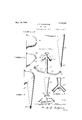
- Fig. l is a front elevation of an amplifier constructed according to the present inven tion and showing a head set supported therein;
- Fig. 2 is a side elevation of the amplifier, the head set being removed;
- Fig. 3 is an enlarged vertical section taken through the lower end of the device with the receivers of the head set therein;
- Fig. 4 is a detail perspective view of the supporting bracket of this invention, the adj ustable and removable parts being omitted;
- Fig. 5 is a side elevation of the bell of the horn in its initial stage of construction
- Fig. 6 is a similar view showing the bell out diagonally at its inner end for matching the body portion of the horn;
- Fig. 7 is a. side elevation of the body portion of the horn, showing the conical body with its beveled outer end for matching the beveled inner end of the bell;
- Fig. 8 is a detail side elevation of the completed horn
- Fig. 9 is a front elevation of a slightly modified construction of horn and supporting bracket, wherein the manifold is constructed as a part of the inner end of the horn; and,
- Fig. 10 is a fragmentary sectional view, enlarged, of the inner end of the horn showing the manifold of Fig. 9 applied thereto.
- the device of this invention adapted for application to telephone head sets of either the two wire system or of the radio construction and in the drawings is illustrated a conventional form of head set comprising a pair of receivers 15 of any approved type which are adapted to be held against the cars by one or more straps 16 which are resilient and adapted to bind across the top of the head.
- the device of this invention is provided with an amplifying horn 17 having a tapering body part which at its inner end opens into a manifold 18 and the manifold is provided with a branch 19 for each receiver 15, the manifold opening upwardly into the horn 17.
- the man ifold 18 may be made separate from the horn 17 and the horn may be provided with a cylindrical shank 20 fitting in the upper end of the manifold and dctachably held therein by a set screw 21. or the like.
- the inanitold is supported upon a standard 22 which at its upper end merges into the bight of the manifold for supporting; it with the branches 19 diverging downwardly at opposite sides of the standard.
- the lower end 01? the standard is provided with.
- a cross arm 23 forming, with the standard, a T-head the arms of which have their outer ends 2%; turned upwardly at an angle of substantially L5 and having threaded openings formed therethrough in axial alinement with the branches 19 of the manifold.
- Each upturned portion 24 of the IT-head carries a set screw 25 which may be adjusted toward and from the adjacent branch 19 and which is adapted to bear against the under side of an adjacent receiver 15 when the head set is in position.
- Each branch 19 ot the manifold may be provided with a yieldable connecting nipple 26 which is carried upon a reduced spud 27 on the end of the branch 19 and which has a free yieldable outer end adapted to become pressed against the open side of the receiver 15 when the adjacent set screw 25 is turned up thereagainst.
- the axes of the branches 19 and set screws 25 are disposed at substantially 4-5 at opposite sides of the standard 22 so that the head set may be placed in position at opposite sides or the standard without removing the receivers 15 from the straps 16 or without disturbing the adjustment. of the receivers or the straps.
- the standard 9.2 may be supported upon a base plate 28 of any suitable configuration, and by means of a screw 29 counter-sunk in the under side of the base plate 528 and threaded upwardly through the lower end of the standard 22 for binding the latter upon the base plate.
- the body port in of ti horn l7 extends upwzuidly pr :ably 1 al' lenient with the stander d and at its liar 1 upper end the body portion of the horn is provided with a diagonally disposed upper edge portion which faces toward the front oi the device and which is adapted to receive the bell portion 30 of the horn.
- the latter is preferably spun in the form shown in Fig. 5, and when so constructed, the lower rear portion oi the bell is cut diagonally as at 31 to meet the upper diagonal edge of the body part oi the hornv 'lhese meeting edges may be welded. or otherwise suitably secured together for completing the horn structure, and as the bell. part is spun the blended vibrations from the receivers of the head set are directed forwardly from the bell 80 without interruption.
- the body portion 32 of the horn merges into maniiold construction and has the diverging branches adapted to communi cute with the receivers oi? the head set and the horn has upon its inner end, between the. branches 33, a threaded socket adapted to receive the correspondingly threaded upper end of a standard 35.
- the standard 35 is otherwise of the same construction as illustrated in the above described form and carries the set screws ior clamping the receivers 15 against the branches 83 of the manifold.
- the set screws 25 may be backed away from the branches of the manifold adequately to receive the receivers 15 therebetween.
- the receivers may be set in position and the set screws 25 turned up thereagainst without exerting any pressure upon the straps 16.
- the receivers 15 are advanced toward the flexibleuiipples 26, which may be of rubber or other suitable composition, so as to seal the receivers against the branches of the manifold.
- the receivers 15 may be matched in the usual manner so as to produce similar vibrations or sounds, and such sounds are conveyed through the manifold into the horn 17 where they are blended and amplified and thus delivered from the bell 30.
- the body part of the manifold is of a cross sectional. area which is substantially equal to twice the area of each of the branches used.
- a bracket having inverted T-shape at one end and inverted it-shape at its other end with the V hollow for connection at its shank to a sound uni-- pliiyinp; horn, and clamping means mounted on the branches of the T end of the bracket for engaging receivers and binding the same against the hollow branches of the Y.
- a sound amplifier comprising a base plate, a manifold bracket rising; from the base plate and having an inverted T-head on its lower end and an inverted Y coupling on its upper end, an amplifying horn secured at its inner end to the upwardly opening shank of the if couplin and set screws secured in the ends of said T-head and extending toward the open ends of the branches of said Y coupling for clamping receivers thereagainst.
- a manifold bracket for connecting head-set receivers to an amplifying horn comprising an inverted Y coupling adapted for connection at its shank to the inner end of the horn, an inverted T-head extending from the bight of the Y coupling, and pressure means carried on the T-head and operative toward the branches of the Y coupling for engaging the receivers and holding the same against said branches.
- a manifold bracket for connecting head-set receivers to an amplifying horn
Landscapes
- Physics & Mathematics (AREA)
- Engineering & Computer Science (AREA)
- Acoustics & Sound (AREA)
- Multimedia (AREA)
- Apparatuses For Generation Of Mechanical Vibrations (AREA)
Description
Nov. 18, 1924- J. T. RHAMSTINE AMPLIFIER Filed April 22 1922 2 Sheets-Sheet l Nov. 18, 1924.
1,516,060 J. T. RHAMSTINE AMPLIFIER 2 Sheets-Sheet 2 Filed ADril 22, 1922 atloz neg Patented Nov. 18, 1924.
UNITED STATES JOHN THOMAS RHAMSTINE, OF DETROIT, MICHIGAN.
AMPLIFIER.
Application fi led April 22, 1922. Serial No. 556,031.
To all 107mm it may CO'ILOQWl-f Be it known that JOHN THOMAS Rrnnrs'rrxn, a. citizen of the United States, resid ing at Detroit, in the county of lVayne and State of Michigan, has invented certain new and useful Improvements in Amplifiers, of which the following is a specification.
The present invention relates to ampliliers adapted particularly for use in connection with telephones, and has for an object to provide an amplifier which may be used in connection with the usual telephone head set for blending together and enlarging the sounds produced at the receivers of the head set.
Another object of this invention is to provide a device of this character which is adapted to support the head set in cooperative relation with an amplifying horn without disturbing the adjustment of the head set or removing the receivers from their straps, and adevice which will maintain the receivers in their normal position during use of the same in connection with the amplifying horn.
The invention further aims at the provision of a device for supporting the receivers of a head set in posit-ion for use in produc ing sound in the ordinary manner of telephone receivers, and in providing a horn with a manifold, the branches of which communicating with the receivers for carrying the vibrations set up by the receivers into the horn where. such vibrations are enlarged or amplified for enlarging the sounds so that they may be heard at a considerable distance from the bell or outlet of the horn.
The invention also embraces a novel construction of horn whereby the bell portion thereof may be symmetrically constructed, such as the bell may be spun and later oined to the tapering body port-ion of th horn wherein the vibrations may be enlarged or amplified, and effecting the joining of the spun bell with the body part of the horn in such manner as not to destroy the blending and enlarging of the sounds set up in the branches of the manifold.
A still further object of the invention is to provide an improved supporting bracket adapted to hold the receivers of a head set and which is provided with a manifold having branches communicating with the receivers and also an outlet with which may be connected the inner end of an amplifying horn, the horn and the head set being supported upon the single bracket.
With the foregoing and other objects in view, the invention will be more fully described hereinafter, and will be more particularly pointed out in the claims appended thereto.
In the drawings, wherein like symbols refer to like or corresponding parts throughout the several views,
Fig. l is a front elevation of an amplifier constructed according to the present inven tion and showing a head set supported therein;
Fig. 2 is a side elevation of the amplifier, the head set being removed;
Fig. 3 is an enlarged vertical section taken through the lower end of the device with the receivers of the head set therein;
Fig. 4: is a detail perspective view of the supporting bracket of this invention, the adj ustable and removable parts being omitted;
Fig. 5 is a side elevation of the bell of the horn in its initial stage of construction;
Fig. 6 is a similar view showing the bell out diagonally at its inner end for matching the body portion of the horn;
Fig. 7 is a. side elevation of the body portion of the horn, showing the conical body with its beveled outer end for matching the beveled inner end of the bell;
Fig. 8 is a detail side elevation of the completed horn;
Fig. 9 is a front elevation of a slightly modified construction of horn and supporting bracket, wherein the manifold is constructed as a part of the inner end of the horn; and,
Fig. 10 is a fragmentary sectional view, enlarged, of the inner end of the horn showing the manifold of Fig. 9 applied thereto.
The device of this invention adapted for application to telephone head sets of either the two wire system or of the radio construction and in the drawings is illustrated a conventional form of head set comprising a pair of receivers 15 of any approved type which are adapted to be held against the cars by one or more straps 16 which are resilient and adapted to bind across the top of the head.
The device of this invention is provided with an amplifying horn 17 having a tapering body part which at its inner end opens into a manifold 18 and the manifold is provided with a branch 19 for each receiver 15, the manifold opening upwardly into the horn 17. As slunvn in Figs. 1 to l, the man ifold 18 may be made separate from the horn 17 and the horn may be provided with a cylindrical shank 20 fitting in the upper end of the manifold and dctachably held therein by a set screw 21. or the like.
In this form ot the inventiom the inanitold is supported upon a standard 22 which at its upper end merges into the bight of the manifold for supporting; it with the branches 19 diverging downwardly at opposite sides of the standard. The lower end 01? the standard is provided with. a cross arm 23 forming, with the standard, a T-head the arms of which have their outer ends 2%; turned upwardly at an angle of substantially L5 and having threaded openings formed therethrough in axial alinement with the branches 19 of the manifold. Each upturned portion 24 of the IT-head carries a set screw 25 which may be adjusted toward and from the adjacent branch 19 and which is adapted to bear against the under side of an adjacent receiver 15 when the head set is in position.
Each branch 19 ot the manifold may be provided with a yieldable connecting nipple 26 which is carried upon a reduced spud 27 on the end of the branch 19 and which has a free yieldable outer end adapted to become pressed against the open side of the receiver 15 when the adjacent set screw 25 is turned up thereagainst.
It will be noted that the axes of the branches 19 and set screws 25 are disposed at substantially 4-5 at opposite sides of the standard 22 so that the head set may be placed in position at opposite sides or the standard without removing the receivers 15 from the straps 16 or without disturbing the adjustment. of the receivers or the straps.
The standard 9.2 may be supported upon a base plate 28 of any suitable configuration, and by means of a screw 29 counter-sunk in the under side of the base plate 528 and threaded upwardly through the lower end of the standard 22 for binding the latter upon the base plate.
The body port in of ti horn l7 extends upwzuidly pr :ably 1 al' lenient with the stander d and at its liar 1 upper end the body portion of the horn is provided with a diagonally disposed upper edge portion which faces toward the front oi the device and which is adapted to receive the bell portion 30 of the horn. For the purpose of insuring symmetry in the construction of the bell 30, the latter is preferably spun in the form shown in Fig. 5, and when so constructed, the lower rear portion oi the bell is cut diagonally as at 31 to meet the upper diagonal edge of the body part oi the hornv 'lhese meeting edges may be welded. or otherwise suitably secured together for completing the horn structure, and as the bell. part is spun the blended vibrations from the receivers of the head set are directed forwardly from the bell 80 without interruption.
In the modification shown in Figs. 9 and 10, the body portion 32 of the horn merges into maniiold construction and has the diverging branches adapted to communi cute with the receivers oi? the head set and the horn has upon its inner end, between the. branches 33, a threaded socket adapted to receive the correspondingly threaded upper end of a standard 35. The standard 35 is otherwise of the same construction as illustrated in the above described form and carries the set screws ior clamping the receivers 15 against the branches 83 of the manifold.
In use, the set screws 25 may be backed away from the branches of the manifold suficiently to receive the receivers 15 therebetween. The receivers may be set in position and the set screws 25 turned up thereagainst without exerting any pressure upon the straps 16. The receivers 15 are advanced toward the flexibleuiipples 26, which may be of rubber or other suitable composition, so as to seal the receivers against the branches of the manifold. The receivers 15 may be matched in the usual manner so as to produce similar vibrations or sounds, and such sounds are conveyed through the manifold into the horn 17 where they are blended and amplified and thus delivered from the bell 30.
it will be noted that the body part of the manifold is of a cross sectional. area which is substantially equal to twice the area of each of the branches used.
It is obvious that various changes and modifications may be made in the details of construction and design of the above spa cifically described embodiment of this invention without departing from the spirit thereof such changes and modifica'l'ums being restricted only by the scope of the following; claims.
Whatis claimed is:
1. In. a sound amplifier, a bracket having inverted T-shape at one end and inverted it-shape at its other end with the V hollow for connection at its shank to a sound uni-- pliiyinp; horn, and clamping means mounted on the branches of the T end of the bracket for engaging receivers and binding the same against the hollow branches of the Y.
2. A sound amplifier comprising a base plate, a manifold bracket rising; from the base plate and having an inverted T-head on its lower end and an inverted Y coupling on its upper end, an amplifying horn secured at its inner end to the upwardly opening shank of the if couplin and set screws secured in the ends of said T-head and extending toward the open ends of the branches of said Y coupling for clamping receivers thereagainst.
3. A manifold bracket for connecting head-set receivers to an amplifying horn, comprising an inverted Y coupling adapted for connection at its shank to the inner end of the horn, an inverted T-head extending from the bight of the Y coupling, and pressure means carried on the T-head and operative toward the branches of the Y coupling for engaging the receivers and holding the same against said branches.
4. A manifold bracket for connecting head-set receivers to an amplifying horn,
comprising a standard, a cross arm at the lower end of the standard having its outer ends upturned at a slight angle, a pair of hollow branches diverging downwardly from the upper end of the standard, a hollow shank communicating with the branches and rising therefrom and adapted for connection with the inner end of the horn, and a pair of set screws carried in said upturned ends of the cross arm for supporting the receivers and adapted to be turned up toward their respective branches for binding and holding the receivers thereagainst.
In testimony whereof he aflixes his signature.
JOHN THOMAS RHAMSTINE.
Publications (1)
| Publication Number | Publication Date |
|---|---|
| US1516060A true US1516060A (en) | 1924-11-18 |
Family
ID=3407654
Family Applications (1)
| Application Number | Title | Priority Date | Filing Date |
|---|---|---|---|
| US1516060D Expired - Lifetime US1516060A (en) | Amplifier |
Country Status (1)
| Country | Link |
|---|---|
| US (1) | US1516060A (en) |
Cited By (2)
| Publication number | Priority date | Publication date | Assignee | Title |
|---|---|---|---|---|
| US2550359A (en) * | 1946-02-08 | 1951-04-24 | Univ Loudspeakers Inc | Loud-speaker mounting |
| EP2207367A1 (en) * | 2009-01-08 | 2010-07-14 | Schweizer Electronic M2S AG | Loudspeaker device and corresponding method for its manufacture |
-
0
- US US1516060D patent/US1516060A/en not_active Expired - Lifetime
Cited By (2)
| Publication number | Priority date | Publication date | Assignee | Title |
|---|---|---|---|---|
| US2550359A (en) * | 1946-02-08 | 1951-04-24 | Univ Loudspeakers Inc | Loud-speaker mounting |
| EP2207367A1 (en) * | 2009-01-08 | 2010-07-14 | Schweizer Electronic M2S AG | Loudspeaker device and corresponding method for its manufacture |
Similar Documents
| Publication | Publication Date | Title |
|---|---|---|
| USD940605S1 (en) | Grille for automobile and/ or other replica thereof | |
| USD909918S1 (en) | Automobile body | |
| USD893443S1 (en) | Speakerphone | |
| USD1044022S1 (en) | Device for collecting and testing a faecal sample | |
| USD995484S1 (en) | Audio mixer | |
| US1516060A (en) | Amplifier | |
| USD971205S1 (en) | Auto stereo mounting device | |
| USD898019S1 (en) | Auto stereo mounting device | |
| USD905047S1 (en) | Auto stereo mounting device | |
| USD898732S1 (en) | Auto stereo mounting device | |
| USD913275S1 (en) | Auto stereo mounting device | |
| USD905043S1 (en) | Auto stereo mounting device | |
| USD1018405S1 (en) | Auto stereo mounting device | |
| USD895100S1 (en) | Air duct | |
| US1570180A (en) | Water plug | |
| USD907030S1 (en) | Auto stereo mounting device | |
| USD904392S1 (en) | Auto stereo mounting device | |
| USD904391S1 (en) | Auto stereo mounting device | |
| USD895099S1 (en) | Air duct | |
| USD1014335S1 (en) | Jockey wheel clamp | |
| US1573634A (en) | Sound amplifier | |
| US1340807A (en) | Telephone-receiver | |
| USD992478S1 (en) | Auto stereo mounting device | |
| US1731523A (en) | Loud-speaking apparatus | |
| USD947171S1 (en) | Auto stereo mounting device |