US1515744A - Wrapping machine - Google Patents
Wrapping machine Download PDFInfo
- Publication number
- US1515744A US1515744A US533219A US53321922A US1515744A US 1515744 A US1515744 A US 1515744A US 533219 A US533219 A US 533219A US 53321922 A US53321922 A US 53321922A US 1515744 A US1515744 A US 1515744A
- Authority
- US
- United States
- Prior art keywords
- slides
- folders
- flap folders
- links
- articles
- Prior art date
- Legal status (The legal status is an assumption and is not a legal conclusion. Google has not performed a legal analysis and makes no representation as to the accuracy of the status listed.)
- Expired - Lifetime
Links
Images


Classifications
-
- B—PERFORMING OPERATIONS; TRANSPORTING
- B65—CONVEYING; PACKING; STORING; HANDLING THIN OR FILAMENTARY MATERIAL
- B65B—MACHINES, APPARATUS OR DEVICES FOR, OR METHODS OF, PACKAGING ARTICLES OR MATERIALS; UNPACKING
- B65B67/00—Apparatus or devices facilitating manual packaging operations; Sack holders
- B65B67/02—Packaging of articles or materials in containers
- B65B67/06—Manually-operable devices for closing bag necks, by applying and securing lengths of string, wire or tape
Definitions
- This invention relates to improvements in wrapping machines.
- My improved wrapping machine is especially designed by me for the wrapping of waxed paper upon loaves of bread and the like, although certain features are desirable 1 for use in other relations; that is, for the Wrapping of other articles.
- the main objects of this invention are: First, to provide an improved wrapping machine by means of which loaves of bread may be rapidly and neatly wrapped.
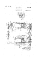
- Sheet 1 is a right-hand side elevation of my improved wrapping machine.
- Fig. II Sheet 2 is a plan view, the wrapping mechanism being broken away.
- Fig. III Sheet 3 is a similar elevation showing the flap folders in one flap turning position.
- Fig. IV Sheet 4 is a side elevation of the folding mechanism with the flap folders in completely actuated position.
- Fig. V Sheet 4 is a detail vertical section on. a line corresponding to line 55 of Fig.
- Fig. VI Sheet 5 is a vertical longitudinal section on a line corresponding to line 6--6 of Fig. VIII with the folder members in initial position.
- Fig. VII, Sheet 6 is a vertical longitudinal section corresponding to that of Fig. VI with the parts in the actuated position shown in Fig. III.
- Fig. VIII, Sheet 7 is a transverse vertical section through the flap folding mechanism on a line corresponding to line 8-8 of Figs. I and VI.
- Fig. IX, Sheet 7 is a detail section on a line corresponding to line 99 of Figs. VIII and X.
- Fig. X, Sheet 7 is a detail section on a line corresponding to line 1010 of Fig. IX.
- Fig. XI Sheet 1 is a vertical transverse section on a line corresponding to line 1111 of Figs. I and II.
- Fig. XII is a detail section on a line corresponding to line 12-42 of Fig. III.
- I provide a sealing way 1 and a cooling way 2 in the form of flat plates or tables across which the articles are pushed. These ways or tables are supported by the standards 3. Uprights 4, 5 and 6 are provided, the uprights 5 being connected by the slotted cross piece 7 while the uprights 6 are connected by the slotted cross or top piece 8. Yielding side plates 9 and 10 are provided for the sealing and cooling ways, these side plates bein continuous. Heating units 11 are mounted on the forward ends of these side plates.
- the side plates are supported by bolts 12, those of the outer side plates being mounted on the uprights to reciprocate therethrough while the bolts of the inner side plate are mounted upon the bar 13 to reciprocate therethrough.
- Coiled springs 14 on these bolts yieldingly support the plates.
- the bar 13 is carried by angle shaped hangers 14 adjustably mounted on the cross pieces 7 and 8 by means of the bolts 15engaging the longitudinal slots 16 thereof so that the inner side plate 11 may be adjusted to loaves of different lengths.
- These side plates yieldingly engage the folded flaps of the wrapped articles, the heating units carried by the plates melting the paraffin of the wrapper sufficiently to cause the flaps to adhere upon cooling which takes place as they are pushed rearwardly over the c oohngway.
- the sealing Way 1 has a heating unit 17 mounted on the under side thereof so that the overlapped edges of the wrapper are also sealed. The wrapped articles are delivered to the sealing way from my improved wrapping mechanism which I will now describe.
- the supporting frame comprises a pan of transverse bed pieces 18 on which are mounted side plates 19 and 20.
- the side plate 19 has an inwardly projecting flange 21 secured to the bed pieces by bolts 22 while the side plate 20 has a similar inwardly projecting flange 23 adjustably secured to the bed pieces by means of the bolts 24 engaging the longitudinal slots 25 in the bed pieces.
- the folding mechanism is duplicated on each side, the only difference therein being that one side is adjustable as indicated so that the mechanism may be adjusted to articles of different lengths corresponding to the adjustment of the side plates of the ways. As these folding mechanisms are duplicates a description of one will suffice. They are, however, actuated together, the actuating rock-shaft 26 being operatively associated with both as will be described.
- the rock-shaft 26 is provided with a pair of actuating levers 27 disposed one at each side so that they may be conveniently grasped with either hand thus permitting the machine to be operated from either side or permitting two operators to use it alternately.
- These levers 27 are adjustably mounted upon the rock-shaft by means of the clips 28.
- the rock-shaft is journaled in the side members 19 and 20.
- the side members 19 and 20 have slide ways 29 at the upper edges thereof, the same being preferably in the form of flanges formed integral with the side plates on wh t channel shaped slides 30 are reciprocatingly mounted. These slides travel back and forth upon the side members as the folding mechanism is actuated and also serve as supports for the article to be wrapped while the wrapper is subjected to the wrapping operations.
- the wrapped articles are pushed from these slides onto the sealing way, the advancing articles pushing the same along on the sealing way and on to the cooling way and discharging the same therefrom.
- Each lever 27 has an actuating link 31 connected thereto by the pivots 32.
- These links are provided at their forward ends with pins 33 engaging slots 34 in the inner flanges 35 of the slides 30 thus providing a lost motion connection between the actuating lovers of these slides.
- the slides have U-shaped uprights 30 at their rear ends and these uprights are provided with projecting studs 36 adapted to coact with the segmental slots 37 in the links 31.
- the links At the lower ends of the slots the links have outwardly offset portions 38 adapted to permit the studs to pass from and enter into the slots, the offsets in effect providing openings for the lower ends of the slots through which the studs may pass.
- the offsets also provide shoulderswhich ride upon the studs as the parts are engaged and disengaged from the slots.
- Pushers 42 are mounted on the slides to push the articles therefrom on the lost motion movement of the levers, that is, the lost motion movement so far as the slides are concerned, so that the articles are disengaged from the slides.
- These pushers are provided with forwardly projecting arms 43 mounted upon the pivots 33.
- the actuating levers also serve to actuate the movable folders. In wrapping articles such as loaves of bread the wrapper is placed over the loaf with the edges overlapping on the under side thereof.
- This operation is performed by the operator who sets the loaf with the wrapper around it upon the slides described between the disk-like flap folders 44, which, when the levers are in normal position, project upwardly at the outer side of the slides so that, as the loaf is placed between them the bottom flap 45 of the wrapper 46 is turned upwardly.
- the flap folder 44 has a disk-like adjustable section 47 which is secured thereto by the set screw 48 so that the section 47 may be adjusted relative to the edge of the member 44 according to the size of the article to be wrapped.
- the adjustable section 47 is secured on the outer side of the flap folder 44 and has an offset 47 therein so that the face of the adjustable section isflush with the face of the folder 44, see Fig. XII.
- the folders 44 are ivoted at 49 upon the outer sides of the slides 30, thefolders being provided with arms 50 mounted upon the pivots. Links 51 connect the folders to the pins 52 on the side plates so that, as the slides are moved forwardly, the folders are thrown down out of the way of the rear flap folders 53.
- These rear flap folders 52-) are mounted on the pivots 49 and are slotted at 54 to engage the pins 52 so that, as the slides'are moved forwardly by the actuating levers, these rear flap folders are swung forwardly to fold the rear flaps forwardly upon the bottom flaps 45.
- the continued forward movement of the slides swings the top flap folders 56 downwardly upon the top flaps 57 folding the same upon the previously folded bottom and rear flaps.
- These flap folders 56 are pivoted at 58 to the up rights 30 on the slides and the lower ends are engaged by the links 59 mounted on the pins 52 and connected to the flap folders by the pivots 60 so that, as the slides move forward, the upper ends of the folders 56 swing downwardly to engage the flaps 57.
- the return of the operating lever to initial position returns all of the movable lap folders to their in tial position so that another loaf or article may be placed in position on the slides and the operation repeated; namely, placing the loaf with the wrapper folder around the same between the flap folders 44, folding the bottom or first flap, the initial actuation of the levers actuating the rear or second flap folders to fold the second flap, continued actuation bringing the top flap folders 56 into engagement with the third or top flaps 57 down upon the previously folded flaps, the further actuation of the levers actuating the pushers and carrying the article between the relatively fixed flap folders 61, folding the front flaps 62, and thus completing the folding operation.
- the paraffin of the coated paper is sufiiciently fused to cause operators.
- the machine is capable of adjustment to various sizes of articles, the structure being designed to accommodate the full range of loaves of bread.
- slides providing a lost motion connection for the actuating levers to the slides, pushers slidably mounted on said slides and provided with forwardly projecting arms engaging said pins on said links, bottom flap folders pivotally mounted upon said slides to project above the slides when in initial position, rear flap folders pivotally mounted on said slides and having forwardly projecting arms provided with segmental slots, top flap folders pivotally mounted on sa1d slides, studs on said side members engaging said slots in said rear flap folder arms, links connecting said bottom flap folders to said studs of said side members, links connecting said top flap folders to said studs on said side members whereby on the forward movement of the slidesithe several flap folders are actuated, front flap folders mounted on said side membersto engage the front flaps as the articles are carried from said slides by said pushers.
- the combination of support members, slides mounted thereon and adapted to receive the articles to be Wrapped said Slides having longitudinal slots therein and provided with projecting studs, actuating levers, actuating links pivotally connected to said actuating levers and having transversely disposed segmental slots adapted to coact with said studs during partial movement of said links, said links being slidably engaged with said slots in said slides providing a lost motion connection for the actuating levers to the slides, pushers operativcly connected to said links, bottom, rear and top flap folders pivotally mounted upon said slides, operating connections for said flap folders -to said supports so that on the forward movement of the slides the several flap folders are ac tuated, and frontflap folders mounted on said side members to engage the front flaps as the articles are carried from said slides by said pushers.
- pusher-s operatively connected with said actuating members, flap folders pivotally mounted on said slides, links connecting said flap folders to said supports whereby on the forward n'iovement of the slides the flap folders are actuated, and front flap folders mounted on said side members to engage the front flaps as the articles are carried from said slides by said pushers.
Landscapes
- Engineering & Computer Science (AREA)
- Mechanical Engineering (AREA)
- Auxiliary Devices For And Details Of Packaging Control (AREA)
Description
w. E. MILLER WRAPPING MACHINE Filed Feb. 1, 1922 7 Sheets-Sheet 1 51mm \Alilfiam Efliller W. E. MILLER WRAPPING MACHINE Filed Feb. 1, 1922 7- Sheets-Sheet 2 W. E. MILLER WRAPPING MACHINE 7 Sheet-Shet 5 Filed Feb. 1, 1922 William E ("IN Ier ATTORNEYS.
I 1,5]l5.74 W. E. MILLER I WRAPPING MACHINE Filed Feb. 1, 1922 7 Sheets-Sheet 4 INVENTOR. m o m Wilham E.!")illcr 4 m 4:
ATTORNEYS.
Nov. 189 1924- W. E. MILLER WRAPPING MACHINE Filed Feb. 1, 1922 7 Sheets-Sheet 5 I WEN-TOR WiHi'iWl E. Miller ATTORNEYS.
W. E. MILLER WRAPPI NG MACHI NE Filed Feb. 1, 1922 7 Sheets-Sheet 6 INVENTOR.
Wall/Mn E. Miller ATTORNEY.
@v. 1189 192%- v 15l5'um% W. E. MILLER WRAPPING MACHINE Filed Feb. 1, 1922 7 Sheets-Sheet 7 ATTORNEYS. P
Patented Nov. I,
it Ii WILLIAM E. MILLER, F KALAMAZOO, MICHIGAN.
WRAPPING MACHINE.
Application filed February 1, 1922/ Seria'l No. 533,219.
T 0 all wiz 0122- it may concern:
Be it known that I, VVILLIAM E. MILLER, a citizen of the United States, residing at Kalamazoo, county of Kalamazoo, State of Michigan, have invented certain new and useful Improvements in Wrapping Machines, of which the following is a specification.
This invention relates to improvements in wrapping machines.
My improved wrapping machine is especially designed by me for the wrapping of waxed paper upon loaves of bread and the like, although certain features are desirable 1 for use in other relations; that is, for the Wrapping of other articles.
The main objects of this invention are: First, to provide an improved wrapping machine by means of which loaves of bread may be rapidly and neatly wrapped.
Second, to provide an improved wrapping 'machine which is simple and convenient to use.
Third, to provide an improved wrapping machine which is very compact in structure although of large capacity. Y
Fourth, to provide an improved wrapping machine which may be adjusted to accommodate loaves of different lengths and depths.
Further objects, and objects pertaining to details and economies of construction and operation will definitely appear from the detailed description to follow.
I accomplish the objects of my invention by the devices and means described in the following specification. The invention is clearly defined and pointed out in the claims.
A structure which is apreferred embodiment of the invention is clearly illustrated in the accompanying drawing forming a part of this application in which:
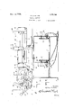
Fig. I, Sheet 1, is a right-hand side elevation of my improved wrapping machine.
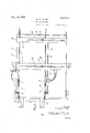
Fig. II, Sheet 2, is a plan view, the wrapping mechanism being broken away.
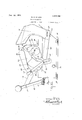
Fig. III, Sheet 3, is a similar elevation showing the flap folders in one flap turning position.
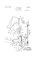
Fig. IV, Sheet 4, is a side elevation of the folding mechanism with the flap folders in completely actuated position.
Fig. V, Sheet 4, is a detail vertical section on. a line corresponding to line 55 of Fig.
I, the flap folders at one side only being slaown as they are duplicated on the other s1 e.
Fig. VI, Sheet 5, is a vertical longitudinal section on a line corresponding to line 6--6 of Fig. VIII with the folder members in initial position.
Fig. VII, Sheet 6, is a vertical longitudinal section corresponding to that of Fig. VI with the parts in the actuated position shown in Fig. III.
Fig. VIII, Sheet 7, is a transverse vertical section through the flap folding mechanism on a line corresponding to line 8-8 of Figs. I and VI.
Fig. IX, Sheet 7, is a detail section on a line corresponding to line 99 of Figs. VIII and X.
Fig. X, Sheet 7, is a detail section on a line corresponding to line 1010 of Fig. IX.
Fig. XI, Sheet 1, is a vertical transverse section on a line corresponding to line 1111 of Figs. I and II.
Fig. XII is a detail section on a line corresponding to line 12-42 of Fig. III.
In the drawing the sectional views are taken looking in the direction of the little arrows at the ends of the section lines and similar numerals of reference refer to similar parts throughout the several views.
Referring to the drawing, I provide a sealing way 1 and a cooling way 2 in the form of flat plates or tables across which the articles are pushed. These ways or tables are supported by the standards 3. Uprights 4, 5 and 6 are provided, the uprights 5 being connected by the slotted cross piece 7 while the uprights 6 are connected by the slotted cross or top piece 8. Yielding side plates 9 and 10 are provided for the sealing and cooling ways, these side plates bein continuous. Heating units 11 are mounted on the forward ends of these side plates.
The side plates are supported by bolts 12, those of the outer side plates being mounted on the uprights to reciprocate therethrough while the bolts of the inner side plate are mounted upon the bar 13 to reciprocate therethrough. Coiled springs 14 on these bolts yieldingly support the plates. The bar 13 is carried by angle shaped hangers 14 adjustably mounted on the cross pieces 7 and 8 by means of the bolts 15engaging the longitudinal slots 16 thereof so that the inner side plate 11 may be adjusted to loaves of different lengths. These side plates yieldingly engage the folded flaps of the wrapped articles, the heating units carried by the plates melting the paraffin of the wrapper sufficiently to cause the flaps to adhere upon cooling which takes place as they are pushed rearwardly over the c oohngway. The sealing Way 1 has a heating unit 17 mounted on the under side thereof so that the overlapped edges of the wrapper are also sealed. The wrapped articles are delivered to the sealing way from my improved wrapping mechanism which I will now describe.
The supporting frame comprises a pan of transverse bed pieces 18 on which are mounted side plates 19 and 20. The side plate 19 has an inwardly projecting flange 21 secured to the bed pieces by bolts 22 while the side plate 20 has a similar inwardly projecting flange 23 adjustably secured to the bed pieces by means of the bolts 24 engaging the longitudinal slots 25 in the bed pieces. The folding mechanism is duplicated on each side, the only difference therein being that one side is adjustable as indicated so that the mechanism may be adjusted to articles of different lengths corresponding to the adjustment of the side plates of the ways. As these folding mechanisms are duplicates a description of one will suffice. They are, however, actuated together, the actuating rock-shaft 26 being operatively associated with both as will be described.
The rock-shaft 26 is provided with a pair of actuating levers 27 disposed one at each side so that they may be conveniently grasped with either hand thus permitting the machine to be operated from either side or permitting two operators to use it alternately. These levers 27 are adjustably mounted upon the rock-shaft by means of the clips 28. The rock-shaft is journaled in the side members 19 and 20. The side members 19 and 20 have slide ways 29 at the upper edges thereof, the same being preferably in the form of flanges formed integral with the side plates on wh t channel shaped slides 30 are reciprocatingly mounted. These slides travel back and forth upon the side members as the folding mechanism is actuated and also serve as supports for the article to be wrapped while the wrapper is subjected to the wrapping operations. The wrapped articles are pushed from these slides onto the sealing way, the advancing articles pushing the same along on the sealing way and on to the cooling way and discharging the same therefrom.
Each lever 27 has an actuating link 31 connected thereto by the pivots 32. These links are provided at their forward ends with pins 33 engaging slots 34 in the inner flanges 35 of the slides 30 thus providing a lost motion connection between the actuating lovers of these slides. The slides have U-shaped uprights 30 at their rear ends and these uprights are provided with projecting studs 36 adapted to coact with the segmental slots 37 in the links 31. At the lower ends of the slots the links have outwardly offset portions 38 adapted to permit the studs to pass from and enter into the slots, the offsets in effect providing openings for the lower ends of the slots through which the studs may pass. The offsets also provide shoulderswhich ride upon the studs as the parts are engaged and disengaged from the slots.
Thus arranged, when the levers 27 are actuated forwardly the slides are carried forward owing to the engagement of the links with the studs 36 until the studs pass out of the slots when the slides stop. The continued forward movement of the links is permitted owing to the lost motion connection of the parts reviously described.
To automatically return the actuating levers to position engaging the slots and studs coiled springs 39 are connected to the rearwardly projecting arms 40 on the slides and to the clips 41 carried by the pivots 33 for the links. When the slides have reached the limit of their forward movement and the studs 36 pass from the slots 37 continued forward movement of the links places the springs 39 under stress so that when the aetuating levers are released-they are returned to the position shown in Fig. VII.
The flap folder 44 has a disk-like adjustable section 47 which is secured thereto by the set screw 48 so that the section 47 may be adjusted relative to the edge of the member 44 according to the size of the article to be wrapped. The adjustable section 47 is secured on the outer side of the flap folder 44 and has an offset 47 therein so that the face of the adjustable section isflush with the face of the folder 44, see Fig. XII. The folders 44 are ivoted at 49 upon the outer sides of the slides 30, thefolders being provided with arms 50 mounted upon the pivots. Links 51 connect the folders to the pins 52 on the side plates so that, as the slides are moved forwardly, the folders are thrown down out of the way of the rear flap folders 53. These rear flap folders 52-) are mounted on the pivots 49 and are slotted at 54 to engage the pins 52 so that, as the slides'are moved forwardly by the actuating levers, these rear flap folders are swung forwardly to fold the rear flaps forwardly upon the bottom flaps 45. The continued forward movement of the slides swings the top flap folders 56 downwardly upon the top flaps 57 folding the same upon the previously folded bottom and rear flaps. These flap folders 56 are pivoted at 58 to the up rights 30 on the slides and the lower ends are engaged by the links 59 mounted on the pins 52 and connected to the flap folders by the pivots 60 so that, as the slides move forward, the upper ends of the folders 56 swing downwardly to engage the flaps 57. These movements are completed during the movement of the slides When the actuating levers are,disengaged from the slides by the passing of the studs 36 from the slots 37 the articles are pushed forwardly from these flap folders between the flap folders 61 which have moldboard shaped edges by which the front flaps 62 are engaged and folded rearwardly upon the previously folded flaps. The flap turners 61 are provided with arms 63 at their lower ends mounted upon the pivots 52 and the bolts 64 engaging the slots 65 in the side members. This permits the swinging adjustment of these flap folders to the height of the article.
The return of the operating lever to initial position returns all of the movable lap folders to their in tial position so that another loaf or article may be placed in position on the slides and the operation repeated; namely, placing the loaf with the wrapper folder around the same between the flap folders 44, folding the bottom or first flap, the initial actuation of the levers actuating the rear or second flap folders to fold the second flap, continued actuation bringing the top flap folders 56 into engagement with the third or top flaps 57 down upon the previously folded flaps, the further actuation of the levers actuating the pushers and carrying the article between the relatively fixed flap folders 61, folding the front flaps 62, and thus completing the folding operation. As the article is pushed upon the sealing conveyor with its folded flaps between the yielding sealing plates, the paraffin of the coated paper is sufiiciently fused to cause operators.
As previously stated, the machine is capable of adjustment to various sizes of articles, the structure being designed to accommodate the full range of loaves of bread.
I have illustrated and described my improvements as I have embodied them in bread wrapping machines. I have not attempted to illustrate any adaptation for other articles as I believe the disclosure made will enable those skilled in the art to which my invention relates to embody or adapt the same as may be desired.
Having thus described my invention what I claim as new and desire to secure by Letters Patent is: j
1. In a structure of the class described, the combination of side members, one of which is mounted for lateral adjustment, inverted channel shaped slides mounted on the tops of said side members and adapted to receive the articles to be wrapped, said slides having longitudinal slots in their inner flanges, inwardly projecting studs on said slides, a rock-shaft journaled in said side members, actuating levers, one at least of which is adjustably mounted on said rockshaft, actuating links pivotally connected to said actuating levers and having inwardly offset portions at the lower edges thereof and transversely disposed segmental slots extending into sa d offsets to coact with said studs during partial movement of said links, said linksbeing also provided with pins engaging said slots in sa d slides providing a lost mot'on connection for the actuating levers to the slides, pushers slidably mounted on said slides and provided with forwardly projecting arms engag'ng said pins on said links, bottom flap folders pivotally mounted upon said slides to project above the slides when in initial position, rear flap folders pivotally mounted on said slides and having forwardly projecting arms provided with segmental slots, top flap folders pivotally mounted on said slides, studs on said side members engaging said slots in said rear flap folder arms, links connecting said bottom flap folders to said studs of said side members, links connecting said top flap folders to said studs on said side members folders mounted on said side members to engage the front flaps as the articles are carried from said slides by said pushers, said front flap folders being provided with rearwardly projectingarms at theirlower ends engaging with said studs on said side members, said side members having seginental. slots, and clamping bolts for said rear flap folders engaging said slots whereby the sa1d front flap folders are supported for ad ustment.
2. In a structure of the class described, the combination of side n'ien'ibers, inverted channel shaped slides mounted on the tops of said side members and. adapted to receive the articles to be wrap 'ied, said slides having longitudinal slots in their inner flanges, inwardly projecting studs on said slides, actuating levers, actuating links pivotally connected to said actuating levers and having inwardly offset portions at the lower edges thereof and transversely disposed segmental slots extending into said offsets to coact with said studs during partial movement of said links, said links being also provided with pins engaging said slots in said. slides providing a lost motion connection for the actuating levers to the slides, pushers slidably mounted on said slides and provided with forwardly projecting arms engaging said pins on said links, bottom flap folders pivotally mounted upon said slides to project above the slides when in initial position, rear flap folders pivotally mounted on said slides and having forwardly projecting arms provided with segmental slots, top flap folders pivotally mounted on sa1d slides, studs on said side members engaging said slots in said rear flap folder arms, links connecting said bottom flap folders to said studs of said side members, links connecting said top flap folders to said studs on said side members whereby on the forward movement of the slidesithe several flap folders are actuated, front flap folders mounted on said side membersto engage the front flaps as the articles are carried from said slides by said pushers.
3. In a structure of the class described. the combination of side members, inverted channel shaped slides mounted on the tops of said side members and adapted to receive the articles to be wrapped, said slides having longitudinal slots in their inner flanges, inwardly projecting studs on said slides, actuating levers, actuating links pivotally connected to said actuating levers and having inwardly offset portions at the lower edges thereof and transversely disposed segmental slots extending into said offsets to react with said studs during partial movement of said links, said links being also provided with pins engaging said slots in said slides providing a lost motion connection for the actuating levers to the slides, pushers slidably mounted on said slides and provided with forwardly projecting arms engaging said pins on said links, coiled springs connecting the pins of said links with said slides whereby the springs are placed under stress after the disengagement of the links from the studs, bottom flap folders pivotally mounted upon said slides to project above the slides when in initial position, rear flap folders pivotally mounted on said slides and having forwardly projecting arms provided with segmental slots, top flap folders pivotally mounted on said slides, studs on said side members engaging said slots in said rear flap folder arms, links connecting said bottom flap folders to said studs of said side members, links connecting said top flap folders to said studs on said side members whereby on the forward movement of the slides the several flap folders are actuated, and front flap folders mounted on said side members to engage the front flaps as the articles are carried from said slides by said pushers.
4. In a'structure of the class described, the combination of side members, one of which is mounted for lateral adjustment, slides mounted on the tops of said side members and adapted to receive the articles to be wrapped, said slides having longitudinal slots therein, inwardly projecting studs an said slides, a rock-shaft journaled in said side members, actuating levers, one at least ofwhich is adjustably mounted on said reekshaft, actuating links pivotally connected to-said actuating levers and having in- Wardly offset portions at the lower edges thereof and transversely disposed segmental slots extending into said offsets to coact with said studs during partial movement of said links, said links being also provided with pins engaging said slots in said slides providing a lost motion connection for the actuating lovers to the slides, pushers slidably mounted on said slides and provided with forwardly projecting arms engaging said pins on said links, bottom flap folders pivotally mounted upon said slides to project above the slides when in initial position, rear and top flap folders pivotally mounted on said slides, said flap folders being operatively connected to said side members so that on the forward movement of the slides the flap folders are actuated. and front flap folders adjustably mounted on said side members to engage the front flaps as the articles are carried from said slides by said pushers.
5. In a structure of the class described, the combination of side members, slides mounted on the tops of said side members and adapted to receive the articles to be wrapped, said slides having longitudinal slots therein, inwardly projecting studs on said slides, a:- tuating levers, actuating links pivotally connected to said actuating levers and having inwardly otl'set portions at the lower edges thereof and transversely disposed segmental slots extending into said oll'sets to coact with said studs during partial movement of said links, said links being also provided with pins engaging said slots in said slides pro- Viding a lost motion connection for the actuating levers to the slides, pushers slidably mounted on said slides and provided with forwardly pro'ecting arms engaging said pins on said lin s, bottom flap folders pivotally mounted upon said slides to project above the slides when in initial position, rear and top flap folders pivotally mounted on said slides, said flap folders be ing operatively connected to said side members so that on the forward movement of the slides the flap folders are actuated, and front flap folders adjustably mounted on said side members to engage the front flaps as the articles are carried from said slides by said pushers.
6. In a structure of the class described, the combination of side members, slides mounted on the tops of said side members and adapted to receive the articles to be wrapped, said slides having longitudinal slots therein, inwardly projecting studs on said slides, actuating levers, actuating links pivotally connected to said actuating levers and having inwardly offset portions at the lower edges thereof and transversely disposed segmental slots extending into said offsets to coact with said studs during partial movement of said links, said links being also provided with ins engaging said slots in said slides provi ing a lost motion connection for the actuating levers to the slides, pushers slidably mounted on said slides and provided with forwardly projecting arms engaging said pins on said links, coiled springs connecting the pins of said links with said slides whereby the springs are placed under stress after the disengage ment of the links from the studs, bottom flap folders pivotally mounted upon said slides to project above the slides when in initial position, rear and top flap folders pivotally mounted on said slides, said flap folders being operatively'connected to said side members so that on the forward movement of the slides the flap folders are actuated, and front flap folders mounted on said side members to engage the front flaps as the articles are carried from said slides by said pushers.
7. In a structure of the class described, the combination of support members, slides mounted thereon and adapted to receive the articles to be Wrapped, said Slides having longitudinal slots therein and provided with projecting studs, actuating levers, actuating links pivotally connected to said actuating levers and having transversely disposed segmental slots adapted to coact with said studs during partial movement of said links, said links being slidably engaged with said slots in said slides providing a lost motion connection for the actuating levers to the slides, pushers operativcly connected to said links, bottom, rear and top flap folders pivotally mounted upon said slides, operating connections for said flap folders -to said supports so that on the forward movement of the slides the several flap folders are ac tuated, and frontflap folders mounted on said side members to engage the front flaps as the articles are carried from said slides by said pushers.
8. In a structure of the class described, the combination of support members, slides mounted thereon adapted to receive the articles to be wrapped, actuating members having lost motion connection to said slides, pushers operatively connected with said actuating members, bottom flap folders pivotally mounted on said slides, rear flap folders pivotally mounted on said slides having a pin and slot connection with said supports, top flap folders pivotall y mounted on said slides, links connecting said bottom and top flap folders to said supports whereby on the for ward movement of the slides the several flap folders are actuated, and front flap folders mounted on said side members to engage the front flaps as the articles are carried from said slides by said pushers.
9. In a structure of the class described, the combination of support members, slides mounted thereon, actuating members having lost motion connection to said slides, bottom flap folders pivotally mounted on said slides, rear flap folders pivotally mounted on said slides having a pin and slot connection with said supports, top flap folders pivotally mounted on said slides, and links connecting said bottom and top flap folders to said supports whereby on the forward movement of the slides the several flap folders are actuated.
10. In a structure of the class described, the combination of support members, slides mounted thereon adapted to receive the articles to be wrapped, actuating members having lost motion connection to said slides, pushers operatively connected with said actuating members, bottom, rear and top flap folders pivotally mounted on said slides, operating connections for said flap folders to said slides so that the [lap folders are actuated, and front flap folders mounted on said side members to engage the front flaps as the articles are carried. from said slides by said pushers.
11. In a structure of the class described, the combination of support members, slides mounted thereon, actuating members having lost motion connection to said slides, bottom, rear and top flap folders pivotally mounted on said slides, and operating connections for said slides so that the flap folders are actuated.
. 12. In a structure of the class described, the combination of support members, slides mounted thereon adapted to receive the articles to be wrapped, actuating i nenrbers having lost motion connection to said shdes,
pusher-s operatively connected with said actuating members, flap folders pivotally mounted on said slides, links connecting said flap folders to said supports whereby on the forward n'iovement of the slides the flap folders are actuated, and front flap folders mounted on said side members to engage the front flaps as the articles are carried from said slides by said pushers.
13. In a structure of the class described, the combination of support men'ibers, slides mounted thereon adapted to receive the articles to be wrapped, actuating members having lost motion connection to said slides, pushers operativcly connected with said actuating members, and front flap folders mounted on said side members to engage the front flaps as the articles are carried from said slides by said pushers.
the combination of support members, slides mounted thereon adapted to receive the articles to be wrapped, actuated members having lost motion connection to said slides, pushcrs operatively connected with said actuating members, fl'ap folders pivotally mounted on said slides having a pin and slot connection with said supports, and front flap folders mounted on said side members to engage the front flaps as the articles are carried from said slides by said pushe-rs.
15. In astructure of the class described, the combination of support members, slides mounted thereon and adapted to receive the articles to be Wrapped, flap folders pivotally mounted on said slides, and links connecting said flap folders to said supports whereby on the forward movement of the slides the flap folders are actuated.
16. In a structure of the class described, the combination of support members, slides mounted thereon and adapted to receive the articles to be wrapped, flap folders pivotally mounted on said slides having a pin and slot connection with said supports, and means for actuating said slides whereby the flap folders are actuated on the forward movement of the slides.
In witness whereof, I have hereunto set my hand and seal.
WILLIAM E. MILLER. [L. s.]
Priority Applications (1)
| Application Number | Priority Date | Filing Date | Title |
|---|---|---|---|
| US533219A US1515744A (en) | 1922-02-01 | 1922-02-01 | Wrapping machine |
Applications Claiming Priority (1)
| Application Number | Priority Date | Filing Date | Title |
|---|---|---|---|
| US533219A US1515744A (en) | 1922-02-01 | 1922-02-01 | Wrapping machine |
Publications (1)
| Publication Number | Publication Date |
|---|---|
| US1515744A true US1515744A (en) | 1924-11-18 |
Family
ID=24125011
Family Applications (1)
| Application Number | Title | Priority Date | Filing Date |
|---|---|---|---|
| US533219A Expired - Lifetime US1515744A (en) | 1922-02-01 | 1922-02-01 | Wrapping machine |
Country Status (1)
| Country | Link |
|---|---|
| US (1) | US1515744A (en) |
Cited By (1)
| Publication number | Priority date | Publication date | Assignee | Title |
|---|---|---|---|---|
| US2725699A (en) * | 1951-11-26 | 1955-12-06 | Glaz Wrap Packaging Co | Apparatus for heat sealing and severing thermoplastic material |
-
1922
- 1922-02-01 US US533219A patent/US1515744A/en not_active Expired - Lifetime
Cited By (1)
| Publication number | Priority date | Publication date | Assignee | Title |
|---|---|---|---|---|
| US2725699A (en) * | 1951-11-26 | 1955-12-06 | Glaz Wrap Packaging Co | Apparatus for heat sealing and severing thermoplastic material |
Similar Documents
| Publication | Publication Date | Title |
|---|---|---|
| US3353327A (en) | Gusset apparatus for bag form and fill machine and method | |
| US3763629A (en) | Wrapping apparatus for bag packs | |
| US1515744A (en) | Wrapping machine | |
| US1986043A (en) | Method of and machine for closing flexible containers | |
| US1118424A (en) | Carton-sealing machine. | |
| US1518534A (en) | Sealing machine | |
| US3237533A (en) | Bag forming machine | |
| US1674408A (en) | Wrapping machine | |
| US1110083A (en) | Bread wrapping and sealing machine. | |
| US1195721A (en) | wrappingfmachine | |
| US1545316A (en) | Bread wrapping and sealing machine | |
| US1324463A (en) | miller | |
| US2515620A (en) | Carton sealing machine | |
| US1492707A (en) | Bread-wrapper sealer | |
| US1999431A (en) | Wrapping of articles | |
| US1056164A (en) | Wrapping-machine. | |
| US1989385A (en) | Wrapping machine | |
| US1960342A (en) | Bread wrapping table | |
| US1984812A (en) | Machine for wrapping rye bread | |
| US874620A (en) | Wrapping-machine. | |
| US1746660A (en) | Machine for wrapping bread and other articles | |
| US548608A (en) | Paper-folding machine | |
| US634627A (en) | Paper-box machine. | |
| US1985466A (en) | Sliced bread wrapping table | |
| US1132586A (en) | Carton-sealing machine. |