US1502889A - Method of and system for radiosignaling - Google Patents
Method of and system for radiosignaling Download PDFInfo
- Publication number
- US1502889A US1502889A US210868A US21086818A US1502889A US 1502889 A US1502889 A US 1502889A US 210868 A US210868 A US 210868A US 21086818 A US21086818 A US 21086818A US 1502889 A US1502889 A US 1502889A
- Authority
- US
- United States
- Prior art keywords
- frequency
- frequencies
- wave
- current
- carrier
- Prior art date
- Legal status (The legal status is an assumption and is not a legal conclusion. Google has not performed a legal analysis and makes no representation as to the accuracy of the status listed.)
- Expired - Lifetime
Links
Images


Classifications
-
- H—ELECTRICITY
- H04—ELECTRIC COMMUNICATION TECHNIQUE
- H04J—MULTIPLEX COMMUNICATION
- H04J1/00—Frequency-division multiplex systems
Definitions
- This invention relates to methods of and systems for radio signaling whereby messages are transmitted as modulations of a high frequency carrier wave.
- An object of the invention is to provide 5 a signaling system which may be highly selective.
- Another object of the invention is to em able the simultaneous transmission of a large number of messages without the use of a 0 correspondingly large number of high frequency carrier waves.
- the present invention provides means whereby the auxiliary carrier currents employed to modulate.
- the carrier current in a double modulation system may each be modulated in accordance with a number of messages, each of which is impressed upon its modulator as a current of audio-frequency which may be selected from the rema-inin message currents in accordance with W ich the same auxiliary carrier frequency is modulated.
- the modulated aux-' iliary carrierwave is passed through a band filter or transmission net work,'which permits only components corresponding in frequency to the. range of the difi'ere'ncebetween the auxiliary carrier frequency and the audio or signalin frequency to pass.
- the frequency of the au'xiliary current be 8 and the frequency of the modulating or message current be p, which in telephony is a variable frequency
- band filter transmits only the component of the modulated auxiliary carrier current having a frequency s79. Since the sum of the frequencies of this transmitted connponent and the message current is constant, either may be termed the frequency conjugate of the other. Since an ascending frequency signal or speech current gives rise to a descending conjugate frequency current, the signal current frequencies are inverted by the action of the modulator and filter.
- the high frequency carrier wave is thenmodulated in accordance with the current component transmitted "by the filter or the frequency conjugate of the-message or signal current.
- a number of auxiliary car-. rier frequencies may be used and each may be modulated in accordance with a number of signal currents of different frequencies.
- the high carrier frequency component of th received waves is first eliminated and each of the modu- 35.
- lated auxiliary carrier frequency components is transmitted to'a modulator from which the various signaling components may be picked out by suitableband filters.
- Fig. 1 represents a radio telephone transmitter set
- Fig. 2 a corresponding receiving arrangement
- Figs. 3 represents a radio telephone transmitter set
- Figs. 1 and 2 illustrate modifications of thecircuits of Figs. 1 and 2, respectively; while Figs. 5 and 6 illustrate the application of my in- 'vention to multiplex radio telegraphy and radio telephony.
- a, b, 0, etc. are constants depending upon the external circuits and the design of the modulator tube. In general, the terms above the second degree are negligible and may be dropped. If the value of e, which is the sum of the electromotive forces set up in the modulator input circuit by generator G and the microphone circuit 1, be written thus:
- the output circuit of the modulator M is coupled to a band filter F of the type described in Patent No. 1,227,113 to G, A. Campbell and is designed to transmit the frequencies corresponding to the range of For example if the range of frequencies In general speech frequencies may be assumed to range from about 100 to 3,000 cycles, and the band of frequencies through-- out this range may be termed the acoustic spectrum of speech. The center of energy of the acoustic spectrum of speech lies at about 900 cycles. The first term of the second member ac sin pt, may therefore be dropped. In general, this term represents frequencies which will be almost wholly eliminated if s is equal to or greater than the maximum value of 2;) so as to make the lower limit of the range of the band filter,
- equation (4) represents a component of frequency Qpt, the maxium energy of which will lie at about 1.800 cycles and this component will be largely eliminated by the band filter. Where 8 is equal to or greater than The last for effective speech be taken as 100 to 3,000 cycles and the auxiliary carrier frequency be chosen as 6,000 cycles, the hand filter F would be designed to pass frequencies between 5,900 and 3,000 cycles. Dropping constant terms and those of frequency outside the range of the band filter, equation (3) reduces to:
- the band filter F is coupled by means of an amplifier A, preferably of the audion type to the input circuit of a modulator M A generator G, supplies high frequency carrier oscillations of frequency (1 to the where is the frequency conjugate of input of the modulator M by means of a transformer coupling 2-.
- Modulator M is coupled by means-ofan amplifier A preferably of the audion type, to an antenna 3 tuned fairly fiat to a frequency i which is the 'meanof the carrier frequency and the frequency of the component repre sented by the term i. 21r and 211' may be inserted between modulator M and amplifier A
- the radiated wave is therefore proportional to:
- this inverted frequency current is of .audio frequency, and would give rise to an unintelligible noise in the receiver, thus effectively masking the talking signal. To this extent the system is secret.
- the band filter F is designed to pass all frequencies within the range of effective speech transmission, or, in the present case, frequencles between zero and the maximum valueof
- the term representing the receiver current contains the factor 10 andthe received signalsv aretherefore increased in intensity by an amount which is dependent upon the amplitude, of the auxiliary carrier oscillation component introduced at the receiving station.
- the current 'ofthe receiver corresponds in frequency and is proportional in amplitude to that in the microphone'circuitl at the transmitter station. Speech may accordingly be transmitted by this, system.
- the modulators M and M corresponding respectively to M and M in the system previously described are of'the balanced typedescribed and claimed in the application of Carson, Serial No. 64,524, filed December 1,1915.
- the expression obtained in this instance contains no term representing a current component of frequency st.
- the modulated auxiliary carrier current is supplied by modulatcr M to the input circuit of a band filter F which may be designed to pass frequencies corresponding to range of The use of this type of modulator thus permits the band filter to have a greater range of transmitted frequencies and to be less sharply selective.
- the generator G produces oscillations of frequency 8 which are modulated as described in accordance with speech currents by the modulator 131,.
- the filter F eliminates all components except those corresponding to the conjugate speech frequency and these remaining components are sup- If desired the other mean side frequency,
- a generator G is arranged to supply auxiliary carrier 0s cillations of frequency 8 to a modulator M of the audion type.
- the auxiliary carrier frequency is modulated in accordance with signaling currents of frequencies a u, and a supplied by generators G G and G respectively.
- Each of these signaling currents may be employed to transmit a message which is determined in accordance with the operation of ansignaling device such as an ordinary telegraph key 7, in the circuit of its individual generator.
- the generator G produces an auxiliary carrier frequency current of frequency which is impressed upon modulator M together with the signaling frequencies of M 11 and 21 which are set up in their respective circuits by generators G G and G
- a band filter F passing a range of frequencies between is coupled to the output circuit of M and transmits a set of current components which may be represented by Filters F and F are coupled to the in. put circuit of modulator M upon which a generator Gr impresses oscillations of the high carrier frequency 9. Oscillations of the resultant frequencies are impressed through a band filter F 6 and an amplifying set A upon the antenna 8 which is tuned fiat to a mean frequency:
- Each auxiliary carrier frequency modulating the high carrier frequency produces two side frequencies, one of which is the sum of the carrierand .auxihary carrier frequencies and th? other of 'Which is their difference. The frequency to this frequency and the highest conjugate signaling frequency, thus eliminating-the side high carrier frequency to the sum of frequencies less than i and the higher radio frequencies.
- Each of these elements corresponds in every Way to the similar elements in the transmitting system of Fig. 1,
- the oscillations received from antenna 8 are impressed by the antenna 9 upon detector D having a high frequency leak pat-h in its output circuit.
- An amplifier A pref- 45 erably of the 'audion type, conductively connects the detector D to a series of band filters F F and F each of which supplies a conjugate signal frequency current to its own modulator. 7
- auxiliary carrier frequencies s s 8,, used for telegraphy are chosen so that where m is any integer, there Will be no combination which will have the same frequency as one of the modulated auxiliary carrier currents. This will permit the band filters F F etc., to eliminate these combination frequency currents and the series represented by the last term in expression (10) will disappear.
- Band filters F, and F each select the conjugate signal frequencies set upon a sincorresponding auxiliary carrier freouency, and supply them to the input circuits of their respective modulators M and M
- filter F is designed to pass a range of frequencies and andfilter F has a corresponding range of.
- a series of band filters F F and F select these and supply each to its respective receiver R R, or
- the filter F 8 and generator G are both coupled to a modulator M which is connected to receivers R R and R through filters F F and F respectively.
- the operation of each of these devices is similar to that of the corresponding elements in the train of devices connected to filter F and hence needs no further explanation.
- Filter F selects thecomponents derived from the talking circuit 11 and impresses them upon the input of a modulator M which is connected to receiver R, by a band filter F Agenerator G supplies auxiliary carrier oscillations of the frequency .9 to the input of modulator M
- the receivers R R and R will therefore serve to receive telegraph messages from the transmitters giving signals of fre quency a a and u respectively, operating with an auxiliary carrier frequency 8,.
- eceivers R R and R will be affected by their respective signals transmitted by aux liary carrier currents of frequency 8 while speech current, will be received by receiver R as determined by microphone circu t 11.
- auxiliary carrier frequency generators at the transmitting station for telegraphic signaling, each operating in conjunction with three signaling frequency generators, and a single auxiliary carrier frequency for telephonic signaling
- this system is capable of operation with a large number of auxiliary carrier frequency generators.
- generator employed for telegraphic purposes may be associated with any number of signaling frequency generators. As an example, let us take the simple case illustrated in Figs. 5 and (5 in which only two auxiliary carrier frequencies are employed for telegraphy and each is modulated in accordance With three signaling frequencies. If
- the frequencies s,u, s 11, to 1 2a 271' will range from 9,500 to 9,300 and filter F,
- the output circuit current of modulator M will have components of frequencies 500, 600 and 700. and filters F F, and F are each designed to pass one of these frequencies. Obviously, with the frequency ranges given. each of the filters F F etc., ten audio frequencies might be used to modulate a single auxiliary carrier frequency. By choosing more auxiliary carrier frequencies and choosing the signaling frequencies more closely, an indefinite number of noninterfering messages may be simultaneously transmitted.
- a single receiving station might have a Each auxiliary carrier frequency generator of auxiliary carrier frequency 8 another receiving station, a generator of frequency s ,.etc., and in this manner multiplex signaling may be carried on with a number of stations yvithout interference.
- the invention is as applicable to transmission of signals by means of waves guided on wires as to transmission by unguided waves. It is also ap plicable to electrical selective systems of any type as well as to signaling systems.
- the method of signaling which comprises modulating a carrier wave in accordance with a wave of inverted signal frequencies.
- the method of signaling comprising modulating a carrier wave in accordance with the frequency conjugate of a signal Wave, and suppressing one of the components of the modulated carrier frequency Wave.
- the method of masking talking signals comprising disproportionally changing the frequency of each of the different frequency components of the talking signals and modifying oscillations in accordance with said components of changed frequencies.
- the method of signaling which comprises transmitting a carrier wave modulated in accordance with the frequency 0011-. jugate of a signaling wave.
- the method of signaling comprising modulating an auxiliary carrier wave in accordance with a signal wave so as to obtain the frequency conjugate of said signal wave, and modulating a carrier wave in accordance with said frequency conjugate.
- the method of signaling comprising modulating an oscillation current in accordance with speech current selecting the components of the resultant modulated oscillation current lying within the frequency range of the (inference in frequencies of said oscillation current and said speech current, and modulating a carrier wave in accordance with said components of changed frequencies.
- the method of receiving slgnals trans mitted as doubly modulated carrier waves which comprises detecting the carrier waves and employing a component of the detected waves to modulate oscillations corresponding in frequency to one of the waves by which the carrier waves were modulated.
- a transmitting station comprising a source of talking current, a source of oscillating current, means for modulat ng said oscillating current in accordance with said talking current, means for selecting the components of said modulated oscillating cur- -rent within a desired range of frequencies and means for modulating a carrier wave by said selected components.
- a signaling system comprislng a modulator having input and output circuits, a source of talking current and a source of oscillating current operatively related to said input circuit, a network coupled to said output circuit for selectively transmitting currents within a limitedjrange of frequencies and means associated'with said network for modulating carrier waves in accordance with the selectively transmitted currents.
- a transmitting station comprising a signaling circuit and a source of alternating current, a modulator operatively related to said signaling circuit and said source, a wave filter connected to said modulator for transmitting with uniformly negligible attenuation a band of frequencies terminated by definite .cut-ofilimits and highly attenuating frequencies without said limits, a source of carrier frequency current, and a operatively related to said wavefilter and said source of carrier frequency current.
- A' receiving station comprising a conductor, 'adetector connected thereto, a source of alternatingcurrent, a modulator having its input circuit operatively connected to said detector andsaid source of alternating current, and a wave filter connected to the output circuit of said modulator, said filter having a. transmission band of uniformly negligible attenuation terminated by definite cut-ofi' limits beyond which the attenuation is large.
- a signalingsystem comprising a generator of carrier waves, means including a transmitter device for doubly modulating said carrier waves, and means for impressing said doubly modulated waves first upon a detector to eliminate the carrier frequency component and .then upon a modulator and wave filter to eliminate one of the modulationcomponents, said filter transmitting -with uniformly negligible attenuation a band of frequencies terminated by sharply defined cut-off limits beyond which the at tenuation is large.
- a multiplex signaling system comprising agenerator of carrier frequency waves, a generator of auxiliary carrier frequency waves associated therewith, means for modulating'said carrier frequency waves in accordance with said auxiliary carrier frequency waves and a plurality of signaling devices for simultaneously transmitting a corresponding plurality of signals associated with said last named generator for varyin the waves generated thereby.
- multiplex signaling system comprising a source of carrier frequency waves
- an auxiliary source of oscillations for modulating said carrier frequency waves, and means for simultaneously modulating said oscillations in accordance with a plurality of independent messages.
- a receiving system for signals transmitted as doubly modulated carrier waves comprising means for selecting components corresponding to the frequency conjugate of the signals, and means for employing said selected components to combine with oscillations of the frequency of one of the components used to modulate the carrier frequency.
- a receiving system comprising a receiving conductor, a detector connected thereto, a band filter connecting said dctector to a modulator for transmitting thereto with uniformly negligible attenuation a band of frequencies terminated by sharply defined cut-off limits and highly attenuating waves beyond said limits, and a source cf oscillations associated with said modulator.
- a source of carrier frequency waves means for simultaneously second modulator having an input circuit Varying said carrier frequency waves in accordance with a plurality of auxiliary carrier frequency waves, and means for simultaneously varying each of said auxiliary carrier frequency waves in accordance with a plurality of'independent energy variations.
- a radio receiving system comprising means for receiving high frequency oscillations and converting the oscillations into lower fretmency inaudible oscillations, a detector, and means for supplying said lowe'r frequency oscillations to said detector, said last mentioned means comprising a band pass filter.
- means for generating a high frequency carrier wave means for generating an .intermediate frequency current.
- means for producing a signal current means for modulating the intermediate frequency current by the signal current, means for modulating the high frequency wave by the modulated intern'iediate frequency current, and a band Filter to prevent the modulation of the high frequency wave by the signal current.
- a modulator In a carrier wave transmission system iuwhich a portion only of the components of a given modulated carrier wave are employed for transmission, the combinationof a modulator, a band filter having a transmission band of uniformly negligible icidenuation terminated by sharply defined cutoff limits beyond which the attenuation is large for restricting transmission to a portion only of the frequency components of the modulated carrier wave, an amplifier for said portion of the components, and a transmission circult for the output of the amplithereto a band filter of which the transmission band is of uniformly negligible attenuation and terminated .
- a signaling system comprising means for varying the amplitude of one wave in accordance with-a plurality.of other waves each representing a signal, and means for suppressing all components of the resultant waves of which the frequencies lie on one side of the frequency of said one wave.
- the method. of signaling which comprises varying the amplitude of one wave in accordance with a plurality of other waves each of different frequency ranges and suppressing all components of the resultant waves having frequencies lying on one side of the frequency of said one wave.
- a modulation system comprising means for varying the amplitude of one wave in accordance with a plurality of other waves of different frequency ranges and suppressing from the modulated output the component having the frequency of saidone wave and all components having frequencies on one side thereof.
- a transmission system comprising means for modulating the amplitude of one wave in accordance with a plurality of frequencies of distinct and different ranges, and means for suppressing from the resultant modulated output components having the frequency of said one wave and of all of said modulating frequencies.
- a sending system comprising means atone station for modifying one wave by another, means for suppressing all components of the resultant modulated wave except one combination frequency, and means at said station whereby the unsuppressed component modulates another Wave.
- a radio transmitting system comprising at one station means for modulating one wave in accordance with another, means for suppressing all components of the resultantwave except one side frequency, means for modulating another wave in accordance with the unsuppressed side frequency, and means at said station for radiating energy controlled in accordance with said last-mentioned modulation output.
- a radio telephone transmission sys tem comprising a station having means for modulating one wave. in accordance with speech, means for suppressing all components of the resultant wave except one side band of a width approximately equal to the width of the speech. means for modulating another wave in accordance with the unsuppressed band, and means at said station for amplifying and radiating the output of said last-mentioned modulating means.
- a successive detection signalling system the combination of the following means arranged in tandem in one channel; a receiving conductor, a detector, amplifying and selecting means, a second detector supplied by currents traversing said amplifying and selecting means, and an inllt) dicating device energized by current supplied by said second detector, said amplifying means producing amplification in addition to any incidental amplification in said detectors.
- a double detection receiving system comprising a channel for transferring waves having inherent characteristics to be reproduced, the combination of successive detectors between which are located amplifying means and a band filter comprising a plurality of sections.
- the method of radio signaling which consists in modulating a plurality of closely spaced carrier frequencies in accordance with low frequency si als, suppressing one side band of each oft e resultant modulated bands,- so as to prevent interference with the unsuppressed band of the adjacent channel, modulating another frequency with modulating a plurality of carrier frequencies in accordance with low frequency currents transmitted over said circuits, means for suppressing one of the resultant side bands, a common modulator, means for impressing the unsuppressed bands on said common modulator in order to modulate current of another frequency, and means for suppressing Waves of all currents having frequencies lying to one side of the other frequency.
- a channel for selecting waves from interfering waves the combination in the order named of the following elements; a detector, a band filter, a second detector, and-a second hand filter.
- a common demodulator for a pluradity of channels, a plurality of demodulators each for a plurality of channels supplied said common demodulator, means for supplying continuous waves to each of said plurality of demodulators, and a plurality of outgoing channels supplied by each of said common demodulators.
- the method of vsignaling which comprises producing a wave having 'a band of frequencies including at least a portion of the frequencies of a speech wave, inverting the frequencies of said produced wave, and modulating a carrier wave in accordance with said wave of inverted frequencies, I 45.
- a signaling system comprisin means for producing a wave of inverted uencies comprising at least a portion of a nd of speech frequencies, and means for modulating a carrier wave in accordance with said produced wave.
Landscapes
- Engineering & Computer Science (AREA)
- Computer Networks & Wireless Communication (AREA)
- Signal Processing (AREA)
- Mobile Radio Communication Systems (AREA)
Description
July 9 p 192%. 7 1,592,889
' H. J. VAN DER' BIJL METHOD OF AND SYSTEM FOR RADIOSIGNALING Orig inal Filed Jan. 8,. 1918 s' SheetsSheet\]V H. J. VAN DER BIJL METHOD OF AND SYSTEM FOR RADIO SIGNALING i an. 8 3 Sheets-Sheet 2 flaw/4 for: Hand/4k J Van d 29/]Z July 29 1924. 1,502,889 H. J. VAN'DER BIJL METHOD OF AND SYSTEM FOR RADiOSIGNALING Original Filed Jan. 8. 191's s sneers-sne p 3 y MM Patented July 29, 1924.
UNITED STATES PATENT OFFICE.
HE DRIX J. vAN DER 131.11., or PRETORIA, SOUTH ArnIcA, AssIeNon 'ro- WESTERN nnncrnro COMPANY, INCORPORATED, or NEW YORK, N, Y., A CORPORATION or NEW YORK.
METHODDF AND SYSTEM FOR BAADIOSIGNAIIING.
Application filed January 8, 1918, Serial No. 210,868. Renewed November 23, 1921. SerialNo. 517,382.
To all whom it may concern:
Be it known that I, HENDRIK J. VAN DER BIJL, a subject of the King of Great Britain, residing at Pretoria, mthe Union of .5 South Africa, have invented certain new and useful Improvements in Methods of and Systems for Radiosignaling, of which the following is a full, clear, concise, and exact description.
This invention relates to methods of and systems for radio signaling whereby messages are transmitted as modulations of a high frequency carrier wave.
An object of the invention is to provide 5 a signaling system which may be highly selective.
Another object of the invention is to em able the simultaneous transmission of a large number of messages without the use of a 0 correspondingly large number of high frequency carrier waves.
In order. to simultaneously transmit a number of non-interfering messages from a single station, it has been proposed to em ploy a different frequency carrier wavefor each message. This method requires a large frequency interval between any two succes sive carrier wavesand the number of simultaneous messages isaccordingly limited, It 30, has also been proposed to transmit several messages upon a single high frequency carrier wave. This may be done by modulats fing each of a number of auxiliary carrier frequency currents, in accordance, with one of a'corresponding number of signal currents, and then modulating a high frequency carrier in accordance with each of the modulated auxiliary carrier currents. The operation of modulating a carrier frequency wave by another wave which has been modulated in accordance with a third wave termed double or successive modulation.
The present invention provides means whereby the auxiliary carrier currents employed to modulate. the carrier current in a double modulation system, may each be modulated in accordance with a number of messages, each of which is impressed upon its modulator as a current of audio-frequency which may be selected from the rema-inin message currents in accordance with W ich the same auxiliary carrier frequency is modulated. The modulated aux-' iliary carrierwave is passed through a band filter or transmission net work,'which permits only components corresponding in frequency to the. range of the difi'ere'ncebetween the auxiliary carrier frequency and the audio or signalin frequency to pass. In other words, if the frequency of the au'xiliary current be 8 and the frequency of the modulating or message current be p, which in telephony is a variable frequency, the
band filter transmits only the component of the modulated auxiliary carrier current having a frequency s79. Since the sum of the frequencies of this transmitted connponent and the message current is constant, either may be termed the frequency conjugate of the other. Since an ascending frequency signal or speech current gives rise to a descending conjugate frequency current, the signal current frequencies are inverted by the action of the modulator and filter. The high frequency carrier wave is thenmodulated in accordance with the current component transmitted "by the filter or the frequency conjugate of the-message or signal current. A number of auxiliary car-. rier frequencies may be used and each may be modulated in accordance with a number of signal currents of different frequencies. At the receiving station the high carrier frequency component of th received waves is first eliminated and each of the modu- 35.
lated auxiliary carrier frequency components is transmitted to'a modulator from which the various signaling components may be picked out by suitableband filters.
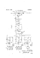
In the drawing, Fig. 1 represents a radio telephone transmitter set; Fig. 2, a corresponding receiving arrangement; Figs. 3
' and 4 illustrate modifications of thecircuits of Figs. 1 and 2, respectively; while Figs. 5 and 6 illustrate the application of my in- 'vention to multiplex radio telegraphy and radio telephony.
In Fig. 1 a generator G and a microphone circuit 1, are inductively'coupled to the input circuit of a modulator M to ce which they supply oscillations of frequency i=cw+bo +co where i represents instantaneous values of current in the output circuit, '0 represents instantaneous E.M.F.s impressed between the cathode and the grid elements, and
a, b, 0, etc., are constants depending upon the external circuits and the design of the modulator tube. In general, the terms above the second degree are negligible and may be dropped. If the value of e, which is the sum of the electromotive forces set up in the modulator input circuit by generator G and the microphone circuit 1, be written thus:
41:6 sin st+e sin pt (2) and be substituted in equation (1) the output current is represented by =ae sin st+ae sin pt+ be sin st+2bee sin st sin pt+bef sin pt (3) The following trigonometric transformations may be made to simplify equation (3) be sin st =be (1 -cos 2st) 211%, sin st sin pt=bee cos (sp)tbec cos (s+p)t 06 sin pt: be,
The output circuit of the modulator M is coupled to a band filter F of the type described in Patent No. 1,227,113 to G, A. Campbell and is designed to transmit the frequencies corresponding to the range of For example if the range of frequencies In general speech frequencies may be assumed to range from about 100 to 3,000 cycles, and the band of frequencies through-- out this range may be termed the acoustic spectrum of speech. The center of energy of the acoustic spectrum of speech lies at about 900 cycles. The first term of the second member ac sin pt, may therefore be dropped. In general, this term represents frequencies which will be almost wholly eliminated if s is equal to or greater than the maximum value of 2;) so as to make the lower limit of the range of the band filter,
term of equation (4) represents a component of frequency Qpt, the maxium energy of which will lie at about 1.800 cycles and this component will be largely eliminated by the band filter. Where 8 is equal to or greater than The last for effective speech be taken as 100 to 3,000 cycles and the auxiliary carrier frequency be chosen as 6,000 cycles, the hand filter F would be designed to pass frequencies between 5,900 and 3,000 cycles. Dropping constant terms and those of frequency outside the range of the band filter, equation (3) reduces to:
566 cos (s-p)t:7c cos rt (5) the speech current.
The band filter F is coupled by means of an amplifier A, preferably of the audion type to the input circuit of a modulator M A generator G, supplies high frequency carrier oscillations of frequency (1 to the where is the frequency conjugate of input of the modulator M by means of a transformer coupling 2-. The characteristic of modulator M is like that of M and may be represented by and since c =k cos rH-e, sin gt,
i a k cos rt a e, sin gt b it cos by} sin gt 2b lce cos rt sin gt I (6) Modulator M is coupled by means-ofan amplifier A preferably of the audion type, to an antenna 3 tuned fairly fiat to a frequency i which is the 'meanof the carrier frequency and the frequency of the component repre sented by the term i. 21r and 211' may be inserted between modulator M and amplifier A The radiated wave is therefore proportional to:
a e, sin qt-l-b ke sin Hm. I
v Referring to Figure 2, a receiving antenna g lc k cos rt or 70 cos rt.
- It may be noted that this is the frequency conjugate of speech current which would be received by parties attempting to pick up the message by means of an ordinary detector system. When 8 is not considerably equation (3) and dropping constant terms and all terms not of radio frequency; I
' greater than 2 this inverted frequency current is of .audio frequency, and would give rise to an unintelligible noise in the receiver, thus effectively masking the talking signal. To this extent the system is secret.
In order to, obtain intelligible signals from this conjugate signal frequency current, the output circuit of amplifier A and the circuit of ,a generator G supplying-oscillations of auxiliary carrier frequency 8, are
both coupled to a modulator M the output;
circuit of which-is connected to the circuit of a receiver R, by means of a band filter F,. v The band filter F, is designed to pass all frequencies within the range of effective speech transmission, or, in the present case, frequencles between zero and the maximum valueof The resultant modulated wave supplied to. the band filter after modulating the auxiliary carrier wave Z0 sin st, emanating from enerator G in accordance with the con- ]ugate signaling frequency wave 7:, cos 'rt is filtered, and the resulting current in the receiver circuit is proportional to. lc k sin pt.
It will be noted that the term representing the receiver current contains the factor 10 andthe received signalsv aretherefore increased in intensity by an amount which is dependent upon the amplitude, of the auxiliary carrier oscillation component introduced at the receiving station. The current 'ofthe receiver corresponds in frequency and is proportional in amplitude to that in the microphone'circuitl at the transmitter station. Speech may accordingly be transmitted by this, system.
In the systems of Figs. 3 and 4, the modulators M and M, corresponding respectively to M and M in the system previously described are of'the balanced typedescribed and claimed in the application of Carson, Serial No. 64,524, filed December 1,1915. A modulator of this type has a characteristic that may be represented by Dropping terms of higher than second degree and substituting the value of o from equation (2), the expression for the current in the ,output circuit of modulator M is i=i'2e sin st-i-bc, sin pt-t-Zbce sin st sin pt (9) .The expression obtained in this instance contains no term representing a current component of frequency st. The modulated auxiliary carrier current is supplied by modulatcr M to the input circuit of a band filter F which may be designed to pass frequencies corresponding to range of The use of this type of modulator thus permits the band filter to have a greater range of transmitted frequencies and to be less sharply selective.
The generator G produces oscillations of frequency 8 which are modulated as described in accordance with speech currents by the modulator 131,. The filter F eliminates all components except those corresponding to the conjugate speech frequency and these remaining components are sup- If desired the other mean side frequency,
could be employed, in which case the transmitting and receiving antenna: would be tuned accordingly.
At the receiving station, signal oscillations are impressed upon a detector D having a high frequency leak 11 in its output circuit which is coupled to an amplifier A The conjugate speech frequency current component ofthe output current of detector D is amplified and then employed to modulate auxiliary carrier frequency oscillations produced by generator G The modulation is effected by a modulator M of the balanced Carson type. The advantage of this form of modulator, as will be seen by reference to equation (8), is that it eliminates the first degree components which are diflicult to weed out. This permits the use of a filter F, which is not as sharply selective as that filter F, and its operation is the same as that of receiver R 7 Figs. 5 and .6 illustrate the application of my invention to multiplex radio telegraphy and telephony. In Fig. 5, a generator G is arranged to supply auxiliary carrier 0s cillations of frequency 8 to a modulator M of the audion type. The auxiliary carrier frequency is modulated in accordance with signaling currents of frequencies a u, and a supplied by generators G G and G respectively. Each of these signaling currents may be employed to transmit a message which is determined in accordance with the operation of ansignaling device such as an ordinary telegraph key 7, in the circuit of its individual generator.
The modulated auxiliary carrier current is passed through a band filter F which transmits the range of frequencies corresponding to pass the filter may 20m, cos (s -u )t=Ean cos r t.
The generator G produces an auxiliary carrier frequency current of frequency which is impressed upon modulator M together with the signaling frequencies of M 11 and 21 which are set up in their respective circuits by generators G G and G A band filter F passing a range of frequencies between is coupled to the output circuit of M and transmits a set of current components which may be represented by Filters F and F are coupled to the in. put circuit of modulator M upon which a generator Gr impresses oscillations of the high carrier frequency 9. Oscillations of the resultant frequencies are impressed through a band filter F 6 and an amplifying set A upon the antenna 8 which is tuned fiat to a mean frequency:
where N represents the number of signal and current sources. Each auxiliary carrier frequency modulating the high carrier frequency produces two side frequencies, one of which is the sum of the carrierand .auxihary carrier frequencies and th? other of 'Which is their difference. The frequency to this frequency and the highest conjugate signaling frequency, thus eliminating-the side high carrier frequency to the sum of frequencies less than i and the higher radio frequencies.
An auxiliary carrier frequency generator G and a microphone circuit llare asso ciated with a modulator M, which 15 connected to a band filter F F ilter F 5 transmits a conjugate speech frequency current to modulator M Each of these elements corresponds in every Way to the similar elements in the transmitting system of Fig. 1,
and the frequency of the auxiliary carrier current generator. and the range of the band filter are preferably about'the same as in the previously described system. It may be noted that as many telephone circuits as may be desired could be employed with this system, each operating upon its own auxiliary carrier frequency. The conjugate speech frequency current would, however, not be audible except in cases where the auxiliary carrier frequency is comparatively low. 40 Referring to the receiving system of Fig. 6, the oscillations received from antenna 8 are impressed by the antenna 9 upon detector D having a high frequency leak pat-h in its output circuit. An amplifier A pref- 45 erably of the 'audion type, conductively connects the detector D to a series of band filters F F and F each of which supplies a conjugate signal frequency current to its own modulator. 7
From previous considerations it will be evident-that the oscillations set up in the output circuit of amplifier A will consist of a number of components, one series of which will represent the conjugate signal frequencies. Another series Will consist of all the interference combinations of the modulated auxiliary carrier frequencies. The waves passed will therefore be proportional to 60 29,, cos r t+ 2b,, cos r t+ +7rE, C cos (r '1- )t+ 10) Where Zlg and 272,, signify the summation of the various conjugate signal frequencies of their respective auxiliary carrier frequencies and E C represents the summation of all the possible combinations of the auxiliary carriers. If, for example, the auxiliary carrier frequencies s s 8,, used for telegraphy are chosen so that where m is any integer, there Will be no combination which will have the same frequency as one of the modulated auxiliary carrier currents. This will permit the band filters F F etc., to eliminate these combination frequency currents and the series represented by the last term in expression (10) will disappear.
Band filters F, and F each select the conjugate signal frequencies set upon a sincorresponding auxiliary carrier freouency, and supply them to the input circuits of their respective modulators M and M For this purpose, filter F, is designed to pass a range of frequencies and andfilter F has a corresponding range of.
A series of band filters F F and F select these and supply each to its respective receiver R R, or
The filter F 8 and generator G are both coupled to a modulator M which is connected to receivers R R and R through filters F F and F respectively. The operation of each of these devices is similar to that of the corresponding elements in the train of devices connected to filter F and hence needs no further explanation.
Filter F selects thecomponents derived from the talking circuit 11 and impresses them upon the input of a modulator M which is connected to receiver R, by a band filter F Agenerator G supplies auxiliary carrier oscillations of the frequency .9 to the input of modulator M The receivers R R and R will therefore serve to receive telegraph messages from the transmitters giving signals of fre quency a a and u respectively, operating with an auxiliary carrier frequency 8,. eceivers R R and R will be affected by their respective signals transmitted by aux liary carrier currents of frequency 8 while speech current, will be received by receiver R as determined by microphone circu t 11.
It may be noted that while I have illustrated only two auxiliary carrier frequency generators at the transmitting station for telegraphic signaling, each operating in conjunction with three signaling frequency generators, and a single auxiliary carrier frequency for telephonic signaling, this system is capable of operation with a large number of auxiliary carrier frequency generators. generator employed for telegraphic purposes may be associated with any number of signaling frequency generators. As an example, let us take the simple case illustrated in Figs. 5 and (5 in which only two auxiliary carrier frequencies are employed for telegraphy and each is modulated in accordance With three signaling frequencies. If
six code messages may be transmitted simultaneously The frequencies s,u, s 11, to 1 2a 271' will range from 9,500 to 9,300 and filter F,
will be designed to pass frequencies of this range. The output circuit current of modulator M will have components of frequencies 500, 600 and 700. and filters F F, and F are each designed to pass one of these frequencies. Obviously, with the frequency ranges given. each of the filters F F etc., ten audio frequencies might be used to modulate a single auxiliary carrier frequency. By choosing more auxiliary carrier frequencies and choosing the signaling frequencies more closely, an indefinite number of noninterfering messages may be simultaneously transmitted.
A single receiving station might have a Each auxiliary carrier frequency generator of auxiliary carrier frequency 8 another receiving station, a generator of frequency s ,.etc., and in this manner multiplex signaling may be carried on with a number of stations yvithout interference.
In its general aspects, the invention. is as applicable to transmission of signals by means of waves guided on wires as to transmission by unguided waves. It is also ap plicable to electrical selective systems of any type as well as to signaling systems.
lVhile I have illustrated and described a number of specific circuit arrangements, it is to be understood that these circuits may be variously modified by those skilled in the art, and that my invention is therefore to be limited only by the scope of the appended claims.
What is claimed is:
1. The method of signaling which coinprises inverting the frequencies of a talking signal so as to produce an unintelligible noise current of audio frequency and modifying oscillations in accordance with said noise current.
2. The method of signaling which comprises modulating a carrier wave in accordance with a wave of inverted signal frequencies.
3. The method of signaling comprising modulating a carrier wave in accordance with the frequency conjugate of a signal Wave, and suppressing one of the components of the modulated carrier frequency Wave.
at. The method of masking talking signals comprising disproportionally changing the frequency of each of the different frequency components of the talking signals and modifying oscillations in accordance with said components of changed frequencies.
5. The method of signaling which comprises transmitting a carrier wave modulated in accordance with the frequency 0011-. jugate of a signaling wave.
6. The method of signaling comprising modulating an auxiliary carrier wave in accordance with a signal wave so as to obtain the frequency conjugate of said signal wave, and modulating a carrier wave in accordance with said frequency conjugate.
7. The method of signaling comprising modulating an oscillation current in accordance with speech current selecting the components of the resultant modulated oscillation current lying within the frequency range of the (inference in frequencies of said oscillation current and said speech current, and modulating a carrier wave in accordance with said components of changed frequencies.
8. The method of masking a talking signal which comprises modulating an oscillation current in accordance with speech current in order to obtain a noise current and modulating a carrier wave in accordance with said noise current. I
9. The method of signalmg comprising modulating an auxiliary carrler wave in accordance with a signaling wave, selecting the components of the modulated auxiliary carrier wave within a given band of frequencies, and modulating a carrier wave in .accordance with said selected auxiliary carrier wave components. q 7
10. The method of receiving slgnals trans mitted as doubly modulated carrier waves which comprises detecting the carrier waves and employing a component of the detected waves to modulate oscillations corresponding in frequency to one of the waves by which the carrier waves were modulated.
11; The method of secret signaling comprising distorting signaling currents to pro-- duce noise currents, modulating carrier frequency currents .m accordance with said noise currents, transmitting energy of said modulated carrier frequency current to procordance with a plurality of independent energy variations and simultaneously varying a carrier frequency wave in accordance with each of said varied auxiliary carrier waves. 13. A transmitting station comprising a source of talking current, a source of oscillating current, means for modulat ng said oscillating current in accordance with said talking current, means for selecting the components of said modulated oscillating cur- -rent within a desired range of frequencies and means for modulating a carrier wave by said selected components.
14. A signaling system comprislng a modulator having input and output circuits, a source of talking current and a source of oscillating current operatively related to said input circuit, a network coupled to said output circuit for selectively transmitting currents within a limitedjrange of frequencies and means associated'with said network for modulating carrier waves in accordance with the selectively transmitted currents.
15. A transmitting station comprising a signaling circuit and a source of alternating current, a modulator operatively related to said signaling circuit and said source, a wave filter connected to said modulator for transmitting with uniformly negligible attenuation a band of frequencies terminated by definite .cut-ofilimits and highly attenuating frequencies without said limits, a source of carrier frequency current, and a operatively related to said wavefilter and said source of carrier frequency current. 16. A' receiving station comprising a conductor, 'adetector connected thereto, a source of alternatingcurrent, a modulator having its input circuit operatively connected to said detector andsaid source of alternating current, and a wave filter connected to the output circuit of said modulator, said filter having a. transmission band of uniformly negligible attenuation terminated by definite cut-ofi' limits beyond which the attenuation is large.
17. A signalingsystem comprising a generator of carrier waves, means including a transmitter device for doubly modulating said carrier waves, and means for impressing said doubly modulated waves first upon a detector to eliminate the carrier frequency component and .then upon a modulator and wave filter to eliminate one of the modulationcomponents, said filter transmitting -with uniformly negligible attenuation a band of frequencies terminated by sharply defined cut-off limits beyond which the at tenuation is large.
18. A multiplex signaling system, comprising agenerator of carrier frequency waves, a generator of auxiliary carrier frequency waves associated therewith, means for modulating'said carrier frequency waves in accordance with said auxiliary carrier frequency waves and a plurality of signaling devices for simultaneously transmitting a corresponding plurality of signals associated with said last named generator for varyin the waves generated thereby.
l9. multiplex signaling system comprising a source of carrier frequency waves,
. an auxiliary source of oscillations for modulating said carrier frequency waves, and means for simultaneously modulating said oscillations in accordance with a plurality of independent messages.
20. A receiving system for signals transmitted as doubly modulated carrier waves comprising means for selecting components corresponding to the frequency conjugate of the signals, and means for employing said selected components to combine with oscillations of the frequency of one of the components used to modulate the carrier frequency.
21.. A receiving system comprising a receiving conductor, a detector connected thereto, a band filter connecting said dctector to a modulator for transmitting thereto with uniformly negligible attenuation a band of frequencies terminated by sharply defined cut-off limits and highly attenuating waves beyond said limits, and a source cf oscillations associated with said modulator.
22. In combination, a source of carrier frequency waves, means for simultaneously second modulator having an input circuit Varying said carrier frequency waves in accordance with a plurality of auxiliary carrier frequency waves, and means for simultaneously varying each of said auxiliary carrier frequency waves in accordance with a plurality of'independent energy variations.
23. A radio receiving system comprising means for receiving high frequency oscillations and converting the oscillations into lower fretmency inaudible oscillations, a detector, and means for supplying said lowe'r frequency oscillations to said detector, said last mentioned means comprising a band pass filter.
24. In a signaling system, means for generating a high frequency carrier wave, means for generating an .intermediate frequency current. means for producing a signal current. means for modulating the intermediate frequency current by the signal current, means for modulating the high frequency wave by the modulated intern'iediate frequency current, and a band Filter to prevent the modulation of the high frequency wave by the signal current.
In a carrier wave transmission system iuwhich a portion only of the components of a given modulated carrier wave are employed for transmission, the combinationof a modulator, a band filter having a transmission band of uniformly negligible attentenuation terminated by sharply defined cutoff limits beyond which the attenuation is large for restricting transmission to a portion only of the frequency components of the modulated carrier wave, an amplifier for said portion of the components, and a transmission circult for the output of the amplithereto a band filter of which the transmission band is of uniformly negligible attenuation and terminated .by sharply defined cut-off limits beyond Which the attenuation is high for suppressing components having the frequency of one of said waves and one combination frequency produced by the interaction of sai waves, and an amplifier for amplifying the unsuppressed components.
28. A signaling system comprising means for varying the amplitude of one wave in accordance with-a plurality.of other waves each representing a signal, and means for suppressing all components of the resultant waves of which the frequencies lie on one side of the frequency of said one wave.
29. The method. of signaling which comprises varying the amplitude of one wave in accordance with a plurality of other waves each of different frequency ranges and suppressing all components of the resultant waves having frequencies lying on one side of the frequency of said one wave.
30. A modulation system comprising means for varying the amplitude of one wave in accordance with a plurality of other waves of different frequency ranges and suppressing from the modulated output the component having the frequency of saidone wave and all components having frequencies on one side thereof.
31. A transmission system comprising means for modulating the amplitude of one wave in accordance with a plurality of frequencies of distinct and different ranges, and means for suppressing from the resultant modulated output components having the frequency of said one wave and of all of said modulating frequencies.
A sending system comprising means atone station for modifying one wave by another, means for suppressing all components of the resultant modulated wave except one combination frequency, and means at said station whereby the unsuppressed component modulates another Wave.
33. A radio transmitting system comprising at one station means for modulating one wave in accordance with another, means for suppressing all components of the resultantwave except one side frequency, means for modulating another wave in accordance with the unsuppressed side frequency, and means at said station for radiating energy controlled in accordance with said last-mentioned modulation output.
34;. A radio telephone transmission sys tem comprising a station having means for modulating one wave. in accordance with speech, means for suppressing all components of the resultant wave except one side band of a width approximately equal to the width of the speech. means for modulating another wave in accordance with the unsuppressed band, and means at said station for amplifying and radiating the output of said last-mentioned modulating means.
In a successive detection signalling system, the combination of the following means arranged in tandem in one channel; a receiving conductor, a detector, amplifying and selecting means, a second detector supplied by currents traversing said amplifying and selecting means, and an inllt) dicating device energized by current supplied by said second detector, said amplifying means producing amplification in addition to any incidental amplification in said detectors.
36. In a double detection receiving system comprising a channel for transferring waves having inherent characteristics to be reproduced, the combination of successive detectors between which are located amplifying means and a band filter comprising a plurality of sections.
37. In a'multiplex transmission system,
- means in tandem for performing a plurality of steps of modulation successively, and means in each channel associated with one of said means in tandem for suppressing the unmodulated carrier component of the modulated Wave before further utilizing said wave in the system.
38. In a multiplex transmission system, means in tandem for performing a plurality of steps of modulation successivel and means in each channel associated with one of said means in tandem for suppressing the unmodulated carrier component an one side frequency of the modulated wave before further utilizing said wave in the system.
39. The method of radio signaling, which consists in modulating a plurality of closely spaced carrier frequencies in accordance with low frequency si als, suppressing one side band of each oft e resultant modulated bands,- so as to prevent interference with the unsuppressed band of the adjacent channel, modulating another frequency with modulating a plurality of carrier frequencies in accordance with low frequency currents transmitted over said circuits, means for suppressing one of the resultant side bands, a common modulator, means for impressing the unsuppressed bands on said common modulator in order to modulate current of another frequency, and means for suppressing Waves of all currents having frequencies lying to one side of the other frequency.
42. In a channel for selecting waves from interfering waves the combination in the order named of the following elements; a detector, a band filter, a second detector, and-a second hand filter. i p
I 43. In a multiplex signaling system,
a common demodulator for a pluradity of channels, a plurality of demodulators each for a plurality of channels supplied said common demodulator, means for supplying continuous waves to each of said plurality of demodulators, and a plurality of outgoing channels supplied by each of said common demodulators.
44; The method of vsignaling which comprises producing a wave having 'a band of frequencies including at least a portion of the frequencies of a speech wave, inverting the frequencies of said produced wave, and modulating a carrier wave in accordance with said wave of inverted frequencies, I 45. A signaling system comprisin means for producing a wave of inverted uencies comprising at least a portion of a nd of speech frequencies, and means for modulating a carrier wave in accordance with said produced wave.
In witness whereof, I hereunto subscribe my name this 31st day of December, A. D. 1917.
'IHENDRIK J. VAN DER BIJL.
Priority Applications (1)
| Application Number | Priority Date | Filing Date | Title |
|---|---|---|---|
| US210868A US1502889A (en) | 1918-01-08 | 1918-01-08 | Method of and system for radiosignaling |
Applications Claiming Priority (1)
| Application Number | Priority Date | Filing Date | Title |
|---|---|---|---|
| US210868A US1502889A (en) | 1918-01-08 | 1918-01-08 | Method of and system for radiosignaling |
Publications (1)
| Publication Number | Publication Date |
|---|---|
| US1502889A true US1502889A (en) | 1924-07-29 |
Family
ID=22784601
Family Applications (1)
| Application Number | Title | Priority Date | Filing Date |
|---|---|---|---|
| US210868A Expired - Lifetime US1502889A (en) | 1918-01-08 | 1918-01-08 | Method of and system for radiosignaling |
Country Status (1)
| Country | Link |
|---|---|
| US (1) | US1502889A (en) |
Cited By (2)
| Publication number | Priority date | Publication date | Assignee | Title |
|---|---|---|---|---|
| US2509716A (en) * | 1944-05-08 | 1950-05-30 | Radio Electr Soc Fr | Arrangement for secret radio telephony |
| US4659875A (en) * | 1982-01-29 | 1987-04-21 | La Radiotechnique | Electronic system for the secret transmission of audio signals |
-
1918
- 1918-01-08 US US210868A patent/US1502889A/en not_active Expired - Lifetime
Cited By (2)
| Publication number | Priority date | Publication date | Assignee | Title |
|---|---|---|---|---|
| US2509716A (en) * | 1944-05-08 | 1950-05-30 | Radio Electr Soc Fr | Arrangement for secret radio telephony |
| US4659875A (en) * | 1982-01-29 | 1987-04-21 | La Radiotechnique | Electronic system for the secret transmission of audio signals |
Similar Documents
| Publication | Publication Date | Title |
|---|---|---|
| US3662268A (en) | Diversity communication system using distinct spectral arrangements for each branch | |
| US2810782A (en) | Frequency modulated communications system with multiplexed audio channels | |
| US2399469A (en) | Secret signaling system | |
| US1495470A (en) | High-frequency transmission | |
| GB725915A (en) | Communication system | |
| US1480217A (en) | Method and means for signaling | |
| US1502889A (en) | Method of and system for radiosignaling | |
| US2389356A (en) | Method of reduction of selective fading | |
| US1592940A (en) | Secret signaling | |
| US2337878A (en) | Carrier wave signaling system | |
| US1571010A (en) | Secret signaling | |
| US2400950A (en) | Privacy signaling system | |
| US1565521A (en) | Secret-communication system | |
| US3125724A (en) | Transmitting | |
| US2026613A (en) | Secrecy system | |
| US2284706A (en) | Arrangement for the transmission of intelligence | |
| US2406034A (en) | Carrier wave signaling system | |
| US2390641A (en) | Multichannel carrier communication system | |
| US1526335A (en) | Secrecy transmission system | |
| US1595135A (en) | Carrier-current signal system | |
| US1904544A (en) | Carrier wave signaling system | |
| US1593365A (en) | Method and system of high-frequency transmission | |
| US2695927A (en) | Multichannel carrier telephone system | |
| US1502811A (en) | High-frequency multiplex signaling system | |
| US1403841A (en) | Frequency-control system |