US1498690A - Snowplow for automobiles - Google Patents
Snowplow for automobiles Download PDFInfo
- Publication number
- US1498690A US1498690A US557398A US55739822A US1498690A US 1498690 A US1498690 A US 1498690A US 557398 A US557398 A US 557398A US 55739822 A US55739822 A US 55739822A US 1498690 A US1498690 A US 1498690A
- Authority
- US
- United States
- Prior art keywords
- plows
- guides
- plow
- automobile
- extending
- Prior art date
- Legal status (The legal status is an assumption and is not a legal conclusion. Google has not performed a legal analysis and makes no representation as to the accuracy of the status listed.)
- Expired - Lifetime
Links
Images

Classifications
-
- B—PERFORMING OPERATIONS; TRANSPORTING
- B60—VEHICLES IN GENERAL
- B60R—VEHICLES, VEHICLE FITTINGS, OR VEHICLE PARTS, NOT OTHERWISE PROVIDED FOR
- B60R19/00—Wheel guards; Radiator guards, e.g. grilles; Obstruction removers; Fittings damping bouncing force in collisions
- B60R19/54—Obstruction removers or deflectors
Definitions
- This invention relates to snow plows, and particularly to snow plows for wheel vehicles, such as motorfcars, trucks, busses, and the like.
- the general .object is to provide a snow plow in the vform of an attachment which may be readily applied to automobile or motor operatedbus'ses or the like and which carries two plows proper disposed in advance of the front wheels of the vehicle
- a furtherobject is to provide a device of this character wherein the lplows are dirigible, either by a connection to the steering bar of the vehicle, or by providing the vehicle witli'a setsteeringpost for the plows.
- Another object is to provide means whereby the plows may be raised and lowered into or out of operative position.
- Figure 2 is a top plan view of the con- -struction illustrated in Figure 1;
- Figure V3 is aperspective view of the shaft for raising or lowering the p'lows
- Figure 4 is a fragmentary top plan Vview showing another manner of shifting the plows
- my invention includes longitudinallyeXtendi-ng supporting :members il() dis- "posed in more or less parallel relation beaieath the body of la'vehicle, these supporting members 10 4bei-ng connected to the .rear axle lhousing,by'anean's ofthe U-'shaped'clamps 11 andto the frontaxle by means ofiU-shaped :clamps
- These lon itudinal'members are formed with a plurality ofperforations 13 :and extending ⁇ across
- My invention is illustrated'in the accomand connecting :the
- members 10 is a transversely VeXtendingcha-nnel iron 1'5 -to which these members 10 :are
- This channel iroiil-lr is connected to both of the supporting beams or members 10 and has a length equal to the distance between the front wheels o'f the inachine or slightly greater than this distance.
- each guide 17 Extending nearly vertically forward of the ends of the channel iron 15 are the guides 17 for the shanksaof the plows. "These guides may be preferably made of channel iron, ⁇ though I do not wish to be limited thereto, and each guide is provided with angle irons 18 and 2O -riveted, bolted or otherwise attached thereto, these anglei-ron sections confronting the ⁇ upper and rlower Alianges of the channel iron .115 land being pivoted thereto by the vertical pivot bolts or pinsv 19.
- the angle iron 20, it -will' be seen from Figure 2 is 'laterally extended so as to form an arm.
- each arm is pivotally connected toa lever 21 pivotedat its middle, ⁇ as at 22, vto the upper liange of'thefchannel iron 15, and thus it-willbelseen that asthis lever ⁇ 21 is oscillated the channel iron ⁇ guides v '.17 will lbe oscillated and that the channel iron guides ⁇ will be oscillated inthe same direction so that these channel iron :guides K are always Aparallel to eachother.
- the ⁇ vertical guides 17 ⁇ have Vupper and ⁇ rlower slots y'25,' and mo ⁇ un-ted"between the iside :flanges of each -"channel iifron is-lthe lverits illustrated, is also made of channel iron and is longitudinally slotted at 27. Pins 28 pass through the slots andV 27 so that the stock, shank ori-post of the plow has limited vertical movement.
- the plow 29 mounted upon the face of each post or stock is the plow 29 which extends upward and rearward and then upward and forward and is disposed inY a plane' at an inclination to the face of the stock.
- Each plow is supported by one or more runners or shoes 30, preferably two in number, as if there is only one shoe 30 it is very liable to run in a rut.
- rlhe rear face of the plow adjacent its inside face is formed with the outwardly projecting flange 31.
- the plows and stocks or posts may be raised and lowered by any suitable mechanism under the control of the driver of the vehicle, and I have illustrated for this purpose a transversely extending shaft 32 which is mounted in bearings upon the upper ends of the guides 17, the shaft being formed with two forwardly projecting arms 33, each of which is connected by a number of links 34 to the corresponding plow stock.
- An arm 35 projects rearwardly from this shaft 32, and attached to this arm is the vertically extending cable 36 which extends downward beneath the pulley 37 mounted upon one of the lbars 10, then extends rearward and beneath the pulley 38, then upward through the floor of the car into position acent the drivers seat and is there provided with a handle 39.
- the chain, cable or other flexible connection will be pulled, which will act to raise the plows.
- Any suitable locking Vdevice may be then engaged by the handle so as to hold the plows raised, and when the handle is released the plows Y will fall to their plowing position.
- the guides 17 will each be braced by a brace 40 which is hingedly connected to the end of the frame bar A of the machine, the forward end of the brace having a socket 41 to receive a ball 42 on the corresponding guide.
- rIhis will permit a relative motion of the guides and the car.
- This frame beam A is ordinarily connected to the elliptical spring B at its forward end, this spring B in'V turn resting on the front axle of the car beneath which the bars 10 pass. rPhis connection, while thus bracing permits the body of the car to rise and fall independently of the chassis in the usual manner.
- the longitudinal members 10 rwill connected to the frame bars A byY means of coiled contractile springs 43 and v-turnbuckles 44, these turnbuckles being connected to clips 45 embracing the corresponding bars 10, the forward end of the spring ⁇ gt4 being connected to. a ,clip or other :Suitable means engaging the frame bars A.
- These springs 43 keep the body of the car from lunging ahead when the shovels or plows strike a large snow drift. In other words, they hold the plow in a normal position but permit the plow to yield when it strikes a drift without putting a too great strain upon the car.
- a sprocket chain, cable or other exible connection 46 Passing around this sprocket wheel or pulley, is a sprocket chain, cable or other exible connection 46 which is crossed in front of the steering post, the extremities of this cable or iexible connection 46 extending to the ends of the lever 21.
- I elaimr- 1 The combination with an automobile having front wheels, of a lnlow supporting frame mounted upon the chassis of the automobile and'including vertically extending guides disposed immediately adjacent the .front wheels of the vehicle, snow plows mounted upon said. guides and extending in front of the front wheels, the plows being vertically movable within the guides and the guides being oscillatahy mounted. for
- a snow. plow of the character described including longitudinally extending supporting b-ars adapted to be attached to the chassis of an automobile, vertical guides hinged to the ends of said supporting bars for lateral oscillation, plows having vertical plow stocks disposed in said guides for vertical movement, contractile springs adapted to connect the longitudinal bars to the frame of the automobile and resist impact on the plows, manually operable means for and adjacent thereto for lateral oscillation independent of the wheel, means whereby the plows may be oscillatably shifted, and means whereby the plows may be raised or lowered.
- a snow,plow attachment for automobiles comprising longitudinally extending frame bars operatively connected to each other and adapted to bel connected to the chassis of an automobile, a transverse bar connecting said longitudinal bars, vertical channel-shaped guides pivotally connected to the ends of the transverse bar, vertical plow stocks disposed in said guides and vertically shiftable therein, the guides and p-low stocks being longitudinally slotted, pins passing through said slots, a plow mounted on each plow stock, a transverse shaft operatively supported upon the guides and having forwardly extending arms flexibly engaged with the upper ends of the plow stocks, and manually operable actuating devices connected to said shaft whereby it may be oscillated to raise or lower the plows.
Description
imam, 1924. 11,498,689 W. G. HEGINBOTTOM SPRING' PIsToN Filed June 167, 19,20
Glitozwu itu. l e:
1,493,690 F. R. HUNZIKER SNOWPLOW FOR AUTOMOBILES Filed' April 29. 1922 2 shregg-sheez 2 Patented June 24, 1924i.
maar@ fr orion.
FRED R. I-IUNZIKER, or TOMAHAWK, WIsooNsInLAssIGNoR oF ONE- HALF .TO 'IQHNLE FLOYD, F TOMAHAWK, WISCONSIN. 1
i SNOWFLOW FOR AUTOMOBILES.
Application filed April 29, 1922. Serial No. 557,398.
` To all whom t may concern.'
Be it known that I, FRED R. HUNZIKER, ya citizen of the United States, residing at Tomahawk, in the county of Lincoln and State of Wisconsin, have invented certain new and useful Improvements in Snowplows for Automobiles, of which the following is a specification, reference being had to the laccompanying drawings.
This invention relates to snow plows, and particularly to snow plows for wheel vehicles, such as motorfcars, trucks, busses, and the like.
The general .object is to provide a snow plow in the vform of an attachment which may be readily applied to automobile or motor operatedbus'ses or the like and which carries two plows proper disposed in advance of the front wheels of the vehicle A furtherobject is to provide a device of this character wherein the lplows are dirigible, either by a connection to the steering bar of the vehicle, or by providing the vehicle witli'a setsteeringpost for the plows.
Another object is to provide means whereby the plows may be raised and lowered into or out of operative position.
Other objects will appear' in the course of the following description.
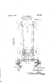
panying drawings, wherein Figure '1 is aside elevation of' a snow plow for automobiles constructed in accordance with my invention, lthe frame of the automobile being in dotted lines; i
Figure 2 is a top plan view of the con- -struction illustrated in Figure 1;
Figure V3 is aperspective view of the shaft for raising or lowering the p'lows;
40 Figure 4 is a fragmentary top plan Vview showing another manner of shifting the plows;
Referring to these drawings, it will be seen that my invention includes longitudinallyeXtendi-ng supporting :members il() dis- "posed in more or less parallel relation beaieath the body of la'vehicle, these supporting members 10 4bei-ng connected to the .rear axle lhousing,by'anean's ofthe U-'shaped'clamps 11 andto the frontaxle by means ofiU-shaped :clamps These lon itudinal'members are formed with a plurality ofperforations 13 :and extending `across My invention is illustrated'in the accomand connecting :the
bolts which maybe inserted in anyone .of
the perforations 113, dependingruponwthe length ofthe vehicle.
Mounted upon 'the forward :ends :of :the
members 10 is a transversely VeXtendingcha-nnel iron 1'5 -to which these members 10 :are
bolted. These members 1'0 maybe U-shaped in cross section or have any :other desired cross section. They are boltedor otherwise connected to the upper flanges of ythechan-nel iron 15 Vand attached to 'the lower `flange :of each channel iron is an upwardly and rearwardly extending brace 16 which :is fbolted,
riveted or votherwise connected to the Acorresponding bar 10. This channel iroiil-lr is connected to both of the supporting beams or members 10 and has a length equal to the distance between the front wheels o'f the inachine or slightly greater than this distance.
Extending nearly vertically forward of the ends of the channel iron 15 are the guides 17 for the shanksaof the plows. "These guides may be preferably made of channel iron, `though I do not wish to be limited thereto, and each guide is provided with angle irons 18 and 2O -riveted, bolted or otherwise attached thereto, these anglei-ron sections confronting the `upper and rlower Alianges of the channel iron .115 land being pivoted thereto by the vertical pivot bolts or pinsv 19. The angle iron 20, it -will' be seen from Figure 2, is 'laterally extended so as to form an arm. l.Each arm is pivotally connected toa lever 21 pivotedat its middle,` as at 22, vto the upper liange of'thefchannel iron 15, and thus it-willbelseen that asthis lever `21 is oscillated the channel iron `guides v '.17 will lbe oscillated and that the channel iron guides `will be oscillated inthe same direction so that these channel iron :guides K are always Aparallel to eachother.
` 'For the. purpose of actuating this lever l21, Ima-y provide a link/22?'connected to one `arm o'f 'a'fbel'l crank lever 2 3 pivoted upon ftheitransverse brace 114, ithe other a-rmofthis 'bell crank lever being connectedjto -t'lie`transversely extending steering rod 24 oftheyniai chine so that las the machine is steered, these vertical guides 17"will*be shifted ,infone Vdi- Afrection' "orthe other.
The `vertical guides 17 `have Vupper and `rlower slots y'25,' and mo`un-ted"between the iside :flanges of each -"channel iifron is-lthe lverits illustrated, is also made of channel iron and is longitudinally slotted at 27. Pins 28 pass through the slots andV 27 so that the stock, shank ori-post of the plow has limited vertical movement. Mounted upon the face of each post or stock is the plow 29 which extends upward and rearward and then upward and forward and is disposed inY a plane' at an inclination to the face of the stock. Each plow is supported by one or more runners or shoes 30, preferably two in number, as if there is only one shoe 30 it is very liable to run in a rut. rlhe rear face of the plow adjacent its inside face is formed with the outwardly projecting flange 31. rThe plows and stocks or posts may be raised and lowered by any suitable mechanism under the control of the driver of the vehicle, and I have illustrated for this purpose a transversely extending shaft 32 which is mounted in bearings upon the upper ends of the guides 17, the shaft being formed with two forwardly projecting arms 33, each of which is connected by a number of links 34 to the corresponding plow stock.
An arm 35 projects rearwardly from this shaft 32, and attached to this arm is the vertically extending cable 36 which extends downward beneath the pulley 37 mounted upon one of the lbars 10, then extends rearward and beneath the pulley 38, then upward through the floor of the car into position acent the drivers seat and is there provided with a handle 39. By drawing upwardV on the handle 39, the chain, cable or other flexible connection will be pulled, which will act to raise the plows. Any suitable locking Vdevice may be then engaged by the handle so as to hold the plows raised, and when the handle is released the plows Y will fall to their plowing position.
Vthe plow over the Vbody of the car,
Preferably the guides 17 will each be braced by a brace 40 which is hingedly connected to the end of the frame bar A of the machine, the forward end of the brace having a socket 41 to receive a ball 42 on the corresponding guide. rIhis will permit a relative motion of the guides and the car. This frame beam A is ordinarily connected to the elliptical spring B at its forward end, this spring B in'V turn resting on the front axle of the car beneath which the bars 10 pass. rPhis connection, while thus bracing permits the body of the car to rise and fall independently of the chassis in the usual manner.
Preferably the longitudinal members 10 rwill connected to the frame bars A byY means of coiled contractile springs 43 and v-turnbuckles 44, these turnbuckles being connected to clips 45 embracing the corresponding bars 10, the forward end of the spring `gt4 being connected to. a ,clip or other :Suitable means engaging the frame bars A. These springs 43 keep the body of the car from lunging ahead when the shovels or plows strike a large snow drift. In other words, they hold the plow in a normal position but permit the plow to yield when it strikes a drift without putting a too great strain upon the car.
I have heretofore described the plows as being oscillated by connection to the steering rod 24 of the car but I do not wish to be limited to this, as under some circumstances, as for instance where the device is to be applied to very heavy cars, it may beA desirable to provide means whereby the driver can shift the plows without putting a strain upon the steering gear of the machine. In Figure 4, I show such a construction, wherein the plow steering post is designated 44 and this steering post being provided with a hand ywheel or like means whereby it may be operated and with a sprocket wheel or pulley 45. Passing around this sprocket wheel or pulley, is a sprocket chain, cable or other exible connection 46 which is crossed in front of the steering post, the extremities of this cable or iexible connection 46 extending to the ends of the lever 21.
It will be seen that with this device a rotation of the steering post will act to coincidently shift both plows in the same direction. This shifting of the plows is necessary in order' that the machine may turn corners and the plows be kept immediately in front of the front wheels and besteered with these front wheels. In the actual practice of this invention to a twentypassenger Oldsmobile bus, the shovels or plows arel three and one-half feet high and three feet wide, but these dimensions will` of course, vary with the different types of car to which the snow plow is applied, the shovels being only about twelve inches wide and three feet high for a Ford.
llVhile I have illustrated details of construction which I have foundlto be particularly of value in actual practice, I do not wish to be limited to this, as it is obvious that many changes might be made in these details and in the arrangement of parts without departing from the spirit of the invention. as defined in the appended claims.
I elaimr- 1. The combination with an automobile having front wheels, of a lnlow supporting frame mounted upon the chassis of the automobile and'including vertically extending guides disposed immediately adjacent the .front wheels of the vehicle, snow plows mounted upon said. guides and extending in front of the front wheels, the plows being vertically movable within the guides and the guides being oscillatahy mounted. for
isa
eral oscillation, and manually operable means for raising or lowering the plows and for oscillating the guides.
2. The combination with an automobile having front steering wheels, of a snow plow therefor comprising a frame mounted upon the chassis of the automobile, vertically disposed guides pivotally mounted upon the frame at its forwardend for lateral oscillation, pivotally disposed'plow stocks slid? ingly engaging said guides for vertical movement, plows mounted upon said plo-w stocks, and manually operable means for oscillating said guides and raising or lowering the plow stocks. f
3. The combination with an automobile of a snow plow mounted upon the chassis of the vehicle and including vertically extending guides having lateral oscillation, plow stocks slidingly engaging said guides for vertical movement, plows carried upon said plow stocks, each plow having a plurality of longitudinally extending shoes at its lower end, means for manually oscillating said guides, and means for raising or lowering the plows.
4. The combination with an automobile having front steering wheels and a transversely extending steering rod, of vertical guides oscillatably supported upon the chassis of the automobile for lateral oscillation, plows having plow stocks disposed in said guides and mounted for vertical movement therein, arms extending laterally from the guides, a lever pivoted at its middle and having its ends connected to said arms, an operative connection between said lever and the steering rod of the machine, and manually operable means for raising or lowering said plow stock in the guides.
5. A snow. plow of the character described including longitudinally extending supporting b-ars adapted to be attached to the chassis of an automobile, vertical guides hinged to the ends of said supporting bars for lateral oscillation, plows having vertical plow stocks disposed in said guides for vertical movement, contractile springs adapted to connect the longitudinal bars to the frame of the automobile and resist impact on the plows, manually operable means for and adjacent thereto for lateral oscillation independent of the wheel, means whereby the plows may be oscillatably shifted, and means whereby the plows may be raised or lowered.
7. A snow,plow attachment for automobiles comprising longitudinally extending frame bars operatively connected to each other and adapted to bel connected to the chassis of an automobile, a transverse bar connecting said longitudinal bars, vertical channel-shaped guides pivotally connected to the ends of the transverse bar, vertical plow stocks disposed in said guides and vertically shiftable therein, the guides and p-low stocks being longitudinally slotted, pins passing through said slots, a plow mounted on each plow stock, a transverse shaft operatively supported upon the guides and having forwardly extending arms flexibly engaged with the upper ends of the plow stocks, and manually operable actuating devices connected to said shaft whereby it may be oscillated to raise or lower the plows.
8. The combination with an automobile having front wheels and a pair of snow plows adapted to be disposed one in front of each front wheel, and a plow supporting frame adapted to be disposed beneath the body of the automobile and detachably engaged with the rear axle housing and with i the front axle.
signature. l
FRED R. HUNZIKER.
Priority Applications (1)
| Application Number | Priority Date | Filing Date | Title |
|---|---|---|---|
| US557398A US1498690A (en) | 1922-04-29 | 1922-04-29 | Snowplow for automobiles |
Applications Claiming Priority (1)
| Application Number | Priority Date | Filing Date | Title |
|---|---|---|---|
| US557398A US1498690A (en) | 1922-04-29 | 1922-04-29 | Snowplow for automobiles |
Publications (1)
| Publication Number | Publication Date |
|---|---|
| US1498690A true US1498690A (en) | 1924-06-24 |
Family
ID=24225225
Family Applications (1)
| Application Number | Title | Priority Date | Filing Date |
|---|---|---|---|
| US557398A Expired - Lifetime US1498690A (en) | 1922-04-29 | 1922-04-29 | Snowplow for automobiles |
Country Status (1)
| Country | Link |
|---|---|
| US (1) | US1498690A (en) |
Cited By (8)
| Publication number | Priority date | Publication date | Assignee | Title |
|---|---|---|---|---|
| US2722064A (en) * | 1952-10-28 | 1955-11-01 | Adolf S Jaffe | Wheel track clearing snow plow for automotive vehicles |
| US2919504A (en) * | 1958-01-24 | 1960-01-05 | George H Rubin | Snow throwers |
| US2931525A (en) * | 1956-10-15 | 1960-04-05 | Massey Ferguson Inc | Mounting apparatus for tractor attachments |
| US3015496A (en) * | 1958-05-16 | 1962-01-02 | Raymond W Campbell | Sub-frame for motor vehicles |
| US3327703A (en) * | 1964-08-13 | 1967-06-27 | Jung Products Inc | Wrist brace |
| US5802746A (en) * | 1997-04-24 | 1998-09-08 | Miller; David L. | Vehicle-mounted snow plowing system |
| US20080276499A1 (en) * | 2007-05-11 | 2008-11-13 | Broten James O | Blade attachment device |
| US20130283647A1 (en) * | 2012-04-25 | 2013-10-31 | International Business Machines Corporation | Automotive vehicle skid recovery system |
-
1922
- 1922-04-29 US US557398A patent/US1498690A/en not_active Expired - Lifetime
Cited By (11)
| Publication number | Priority date | Publication date | Assignee | Title |
|---|---|---|---|---|
| US2722064A (en) * | 1952-10-28 | 1955-11-01 | Adolf S Jaffe | Wheel track clearing snow plow for automotive vehicles |
| US2931525A (en) * | 1956-10-15 | 1960-04-05 | Massey Ferguson Inc | Mounting apparatus for tractor attachments |
| US2919504A (en) * | 1958-01-24 | 1960-01-05 | George H Rubin | Snow throwers |
| US3015496A (en) * | 1958-05-16 | 1962-01-02 | Raymond W Campbell | Sub-frame for motor vehicles |
| US3327703A (en) * | 1964-08-13 | 1967-06-27 | Jung Products Inc | Wrist brace |
| US5802746A (en) * | 1997-04-24 | 1998-09-08 | Miller; David L. | Vehicle-mounted snow plowing system |
| US20080276499A1 (en) * | 2007-05-11 | 2008-11-13 | Broten James O | Blade attachment device |
| US7540103B2 (en) * | 2007-05-11 | 2009-06-02 | Broten James O | Blade attachment device |
| US20130283647A1 (en) * | 2012-04-25 | 2013-10-31 | International Business Machines Corporation | Automotive vehicle skid recovery system |
| US9139175B2 (en) * | 2012-04-25 | 2015-09-22 | International Business Machines Corporation | Automotive vehicle skid recovery system |
| US9719224B2 (en) | 2012-04-25 | 2017-08-01 | International Business Machines Corproation | Automotive vehicle skid recovery system |
Similar Documents
| Publication | Publication Date | Title |
|---|---|---|
| US1498690A (en) | Snowplow for automobiles | |
| US2144311A (en) | Snow removing mechanism | |
| US1567684A (en) | Walking vehicle | |
| US2774435A (en) | Leveling tractor and drawbar construction | |
| US1620099A (en) | Cultivator attachment for tractors | |
| US2705444A (en) | Hydraulic hitch control for tractors | |
| US1661511A (en) | Automobile sleigh | |
| US1004733A (en) | Automobile-brake. | |
| US1512595A (en) | Control extension for tractors | |
| US1602466A (en) | Safety rear-axle brace | |
| US2023015A (en) | Front drive snowmobile | |
| US1686170A (en) | Detachable steering mechanism for tractors | |
| US1599262A (en) | Steering device for motor tractors | |
| US1939472A (en) | Guide attachment for tractors | |
| US1318440A (en) | Headmost fob automobiles ob the like | |
| US1369606A (en) | Implement attachment for tractors | |
| US1850691A (en) | Automobile sleigh | |
| US1929773A (en) | Control mechanism for tractor driven implements | |
| US1625019A (en) | Road-scraper-adjusting mechanism | |
| US1636145A (en) | Brake mechanism and the like | |
| US1541038A (en) | Vehicle control | |
| US1434503A (en) | Dirigible headlight construction for automobiles | |
| US1843327A (en) | Tractor guide | |
| US1461198A (en) | Controlling device for drawn implements | |
| US1359505A (en) | Steering mechanism |