US14709A - Alexander buchanan - Google Patents
Alexander buchanan Download PDFInfo
- Publication number
- US14709A US14709A US14709DA US14709A US 14709 A US14709 A US 14709A US 14709D A US14709D A US 14709DA US 14709 A US14709 A US 14709A
- Authority
- US
- United States
- Prior art keywords
- steam
- valve
- pressure
- pipe
- alexander
- Prior art date
- Legal status (The legal status is an assumption and is not a legal conclusion. Google has not performed a legal analysis and makes no representation as to the accuracy of the status listed.)
- Expired - Lifetime
Links
Images


Classifications
-
- F—MECHANICAL ENGINEERING; LIGHTING; HEATING; WEAPONS; BLASTING
- F16—ENGINEERING ELEMENTS AND UNITS; GENERAL MEASURES FOR PRODUCING AND MAINTAINING EFFECTIVE FUNCTIONING OF MACHINES OR INSTALLATIONS; THERMAL INSULATION IN GENERAL
- F16K—VALVES; TAPS; COCKS; ACTUATING-FLOATS; DEVICES FOR VENTING OR AERATING
- F16K11/00—Multiple-way valves, e.g. mixing valves; Pipe fittings incorporating such valves
- F16K11/02—Multiple-way valves, e.g. mixing valves; Pipe fittings incorporating such valves with all movable sealing faces moving as one unit
- F16K11/06—Multiple-way valves, e.g. mixing valves; Pipe fittings incorporating such valves with all movable sealing faces moving as one unit comprising only sliding valves, i.e. sliding closure elements
- F16K11/065—Multiple-way valves, e.g. mixing valves; Pipe fittings incorporating such valves with all movable sealing faces moving as one unit comprising only sliding valves, i.e. sliding closure elements with linearly sliding closure members
- F16K11/0655—Multiple-way valves, e.g. mixing valves; Pipe fittings incorporating such valves with all movable sealing faces moving as one unit comprising only sliding valves, i.e. sliding closure elements with linearly sliding closure members with flat slides
-
- Y—GENERAL TAGGING OF NEW TECHNOLOGICAL DEVELOPMENTS; GENERAL TAGGING OF CROSS-SECTIONAL TECHNOLOGIES SPANNING OVER SEVERAL SECTIONS OF THE IPC; TECHNICAL SUBJECTS COVERED BY FORMER USPC CROSS-REFERENCE ART COLLECTIONS [XRACs] AND DIGESTS
- Y10—TECHNICAL SUBJECTS COVERED BY FORMER USPC
- Y10T—TECHNICAL SUBJECTS COVERED BY FORMER US CLASSIFICATION
- Y10T137/00—Fluid handling
- Y10T137/8593—Systems
- Y10T137/86493—Multi-way valve unit
- Y10T137/86574—Supply and exhaust
- Y10T137/8667—Reciprocating valve
Definitions
- My invention is for certain improvements in balance slide valves and the principle of my said invention consists in a peculiar application of the steam, whereby the pressure of steam on one side is neutralized by an equivalent force or pressure on the opposite side.
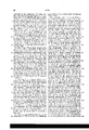
- Fig. II is a sectional view of a portion of the cylinder, its steam and exhaust ports, together with the valve and the case inclosing it, which latter although resembling the ordinary steam chest, is not strictly such, as the latter is found within the valve itself.
- Fig. IV a perspective view of the valve is given exhibiting its under side; in Fig. I a portion of its top is shown, and in Figs. II and III longitudinal and transverse sections are also shown.
- the parts (e) and (e) form a valve of the ordinary construction, and this is inclosed by a cover sufliciently large to leave a channel or space (f) between. lVhen the valve therefore is on its seat upon the cylinder, in whatever position it may be, this cover part will always embrace the two steam ports a) and (a) at its end, as well as the two channel openings (d al) Figs. I and III at the sides.
- the steam which passes through the pipe (0) will therefore discharge by d) into the channel (f) and will thence pass into the cylinder by the ports (a) or (a) according to the position of the valve, and as represented in Fig. II.
- the passage (cl) is always open to (f) because the motion of the valve is in a direction parallel therewith, and thus the space (f) becomes in fact the steam chest.
- the part (g) is a tube cast in the valve to admit the passage of a stem or rod by which it receives itsI motion1 in the usual way.
- Figs. V andy VI are views of apparatus connected with the operation of the valve. That shown in Fig. V is the instrument for effecting the maintenance of the proper pres'-Y sure; of steam in (h) and Fig. VI shows anV apparatus for discharging the water from the condensed steam in the casey (h). The manner in which these are connected with the valve is shown inf Fig. I.
- the -steam from the boiler must pass through the regu.- lator Fig. V in its way to the steaml case and the operation of the regulator is such as to allow only so much to pass as will accomplish the balancing of the valve.
- the steam is represented' as being taken. out of the steam pipe (c) leading ,A tothe engine as. at. Fig, I; after passing through thev regulator it flowsv into (h) by the pipe
- the regulator isconstructed as follows.
- Fig. V is a cylinder fitted with a piston (.c) the rod of which passes downward through a stufling box into another chamber' ⁇ (.Z) where it terminates with a valve (Z) fitting in an aperture leading to said chamber.
- the valve (Z) a pipe continues downward, some distance, out of whichtwo pipes lead, the upper one being the pipe before named.
- the ⁇ other pipe in starts near the bottom and turning upward intersects the pipe (i) and terminates at its'other end in thex cylinder (7n). Between and (m) is a valve (nl) opening upward as shown.
- the apparatus Fig. VI is constructed as follows: At (0) is a vessel, water tight, in the bottom of which is ay balanced valve (o) tc the ⁇ stem of which valve is attached a. float (.l)
- At (Z). isa.v pipe leadin from (o) to the ⁇ steam case: (h) Fig. I; at g) is a discharge iquire considerable power to ⁇ move it. ⁇ balance the great pressure of the direct steam beneath in quired in (It) This is obtained by ott the flow of steam through (i as enough has entered (h) to accomplish the gobject, and this iseffected. by means of the piston (-s) Fig. V where it will be seen ithat a: branch pipe (m) leads a portion of lthe steam off from into the cylinder and acting on the piston (c) forces down -the valve (Z) and stopsk the further influx ylof the steam through (i). seen that unless the area of the piston (c) Iwas greater than that of the valve (Z) no pipe andy at (r) is a safety valve of common construction.
- valve is operated in the ordinary vibratory manner; steam' entering through- (c) flows on and enters the channel (f) as before set forth, from thisy it passes into the ports (a) or (a) according to the position of the valve, the exhaust through (b) bein as usual; steam will also flow through t e pipe into (m) here it escapes by raismg the valve (Z) and thence passes intoy the steam case (h).
- valve (iZ) In practice, as the steam in (It) must bel all the time condensing andl therefore diminishing in volume, the valve (iZ) will be always raised just so high. as to permit the requisite flow of. steam tosupply this source of waste and maintain the equi- ⁇ librium of the valve. I have described the piston (c) and ⁇ valve (Z) ashaving the same relative difference in area that the two steam surfaces of the main valve have. In
- valve (In.) is to permit the steam to flow back into (i) in case from any cause there should be an excess of pressure in (It) and by this flowing back it would be relieved. This is however an occurrence which can seldom happen.
Landscapes
- Engineering & Computer Science (AREA)
- General Engineering & Computer Science (AREA)
- Mechanical Engineering (AREA)
- Control Of Turbines (AREA)
Description
UNITED STATES PATENT OFFICE.
ALEXANDER BUCHANAN, OF NEW YORK, N. Y.
BALANCED SLIDE-VALVE FOR STEAM-ENGINES.
Specification of Letters Patent No. 14,709, dated April 22, 1856.
To all 'whom t may concern Be it known that I, ALEXANDER BUCH- ANAN, of New York, county of New York, and State of New York, have invented certain new and useful Improvements in Slide- Valves for Steam-Engines; and I do hereby declare that the following is a full, clear, and exact description of the same, reference being made to the annexed drawing, making a part of this specification, in which- Figure I is a top view partly in s ection and having the cover removed; Figs. II and III are longitudinal and transverse verticalsections; Figs., IV, V and VI are of parts in detail; and similar letters indicate similar parts throughout.
My invention is for certain improvements in balance slide valves and the principle of my said invention consists in a peculiar application of the steam, whereby the pressure of steam on one side is neutralized by an equivalent force or pressure on the opposite side.
In the theoretical operation of my valve a perfect equilibrium is produced, but in practice it is required that there shall always be sufficient pressure upon the valve to keep it in its seat, all of which is readily accomplished by my improvement. `Inasmuch also as the surface under the valve is much less than the upper, the pressure of the steam upon these must be different in the proportion of the areas exposed in order to produce an equality, and to accomplish this by steam taken from the same boiler constitutes a material part of my invention, as will be made apparent in the following description of the construction and operation of my said valve. In that operation the steam is admitted to the ports from the under side= Athe exhaust being also from that side. Consequently were nothing interposed to prevent, the valve would be forced up from its seat and the operation of course be ended. To obviate this, steam pressure is applied f `l to the opposite surface and suiiciently in excess to keep down the valve as before mentioned. All this is accomplished by self regulating parts operating automatically. I shall therefore describe lirst the construc- Ytion of the valve and the manner `in which the steam passes for operating the engine, and afterward the application of the balancing force.
In Fig. II is a sectional view of a portion of the cylinder, its steam and exhaust ports, together with the valve and the case inclosing it, which latter although resembling the ordinary steam chest, is not strictly such, as the latter is found within the valve itself. f
At (a a) are the steam ports and channel ways in the cylinder, and (b) the exha ust passage.
At (c) are shown steam ways, cast in the metal of the cylinder, and running across the same outside of and parallel with the two steam channels (a af), to these, on one side of the cylinder, is attached the steam nozzle (c) as in Figs. I and III and they are also connected to two others which form the outlet, as shown at Figs. I and II. The valve is of such shape as to cover these outlets as well as the regular steam ports (a) and (a).
In Fig. IV a perspective view of the valve is given exhibiting its under side; in Fig. I a portion of its top is shown, and in Figs. II and III longitudinal and transverse sections are also shown. The parts (e) and (e) form a valve of the ordinary construction, and this is inclosed by a cover sufliciently large to leave a channel or space (f) between. lVhen the valve therefore is on its seat upon the cylinder, in whatever position it may be, this cover part will always embrace the two steam ports a) and (a) at its end, as well as the two channel openings (d al) Figs. I and III at the sides. The steam which passes through the pipe (0) will therefore discharge by d) into the channel (f) and will thence pass into the cylinder by the ports (a) or (a) according to the position of the valve, and as represented in Fig. II. The passage (cl) is always open to (f) because the motion of the valve is in a direction parallel therewith, and thus the space (f) becomes in fact the steam chest. The part (g) is a tube cast in the valve to admit the passage of a stem or rod by which it receives itsI motion1 in the usual way. The means for balancing the valve and keeping it down on its seat will now be described. It is apparent from what has been set forth that the valve would be blown upward, by the steam passing through (d), with a force due to the pressure of the steam and the surface exposed to that ressure, kwhich is, the area of the channel and it will therefore require a like force applied to the top of the valve to keep itin place. This I accomplish by the applicationE of steam,- and the valve therefore is enveloped` in a steam tight case (It) of suiiicient strength to withstand the pressure. It will be seen that as the area exposed by the outside of the valve is very much greater thanv the area of the channel (f), steam of less pressure will be required within the case (h) to overcome the force of that exerted in the channel, and the difference will be as the' respective ratios of and f); for example, if the area of (f) be ten square inches, and the area of (f) onehundred square inches then will steam of ten pounds to the square inchin (lz) balance the force of steam of one hundred pounds to the square inch` in (f). To apply and maintain the steam in (71,) at such. relative pressure to that in (f) as will insure the full balancing of the valve, constitutesone of the important features of my invention. q
In Figs. V andy VI are views of apparatus connected with the operation of the valve. That shown in Fig. V is the instrument for effecting the maintenance of the proper pres'-Y sure; of steam in (h) and Fig. VI shows anV apparatus for discharging the water from the condensed steam in the casey (h). The manner in which these are connected with the valve is shown inf Fig. I. The -steam from the boiler must pass through the regu.- lator Fig. V in its way to the steaml case and the operation of the regulator is such as to allow only so much to pass as will accomplish the balancing of the valve. In the figure the steam is represented' as being taken. out of the steam pipe (c) leading ,A tothe engine as. at. Fig, I; after passing through thev regulator it flowsv into (h) by the pipe The regulator isconstructed as follows.
At Fig. V is a cylinder fitted with a piston (.c) the rod of which passes downward through a stufling box into another chamber'` (.Z) where it terminates with a valve (Z) fitting in an aperture leading to said chamber. Beneath: the valve (Z) a pipe continues downward, some distance, out of whichtwo pipes lead, the upper one being the pipe before named. Out of the chamber (Z) the pipe (f7) forming practically a continuation of (i) leads and connects with the= steam case (it) as in Fig; I.r The` other pipe in starts near the bottom and turning upward intersects the pipe (i) and terminates at its'other end in thex cylinder (7n). Between and (m) is a valve (nl) opening upward as shown. The apparatus Fig. VI is constructed as follows: At (0) is a vessel, water tight, in the bottom of which is ay balanced valve (o) tc the` stem of which valve is attached a. float (.l
At (Z). isa.v pipe leadin from (o) to the` steam case: (h) Fig. I; at g) is a discharge iquire considerable power to` move it. `balance the great pressure of the direct steam beneath in quired in (It) This is obtained by ott the flow of steam through (i as enough has entered (h) to accomplish the gobject, and this iseffected. by means of the piston (-s) Fig. V where it will be seen ithat a: branch pipe (m) leads a portion of lthe steam off from into the cylinder and acting on the piston (c) forces down -the valve (Z) and stopsk the further influx ylof the steam through (i). seen that unless the area of the piston (c) Iwas greater than that of the valve (Z) no pipe andy at (r) is a safety valve of common construction.
The operation will now be as follows:
It isunderstood that the valve is operated in the ordinary vibratory manner; steam' entering through- (c) flows on and enters the channel (f) as before set forth, from thisy it passes into the ports (a) or (a) according to the position of the valve, the exhaust through (b) bein as usual; steam will also flow through t e pipe into (m) here it escapes by raismg the valve (Z) and thence passes intoy the steam case (h). through (i) but unless means Were taken to' prevent it the pressure in` (h) would soon be` equal tot that in (f) and of course,` as before mentionedy as the outer surface of the valve exposed tothe pressure of the steam is much greater than that on the under side it would be forced d'own upon its seat, andv would in consequence rea much less is reshutting so soon But it will be such. effectwould take place.v And this is precisely the condition of the two, for the areasfof the piston (/v) and valve (Z) are is-destroyed and (-Z) Visraised whereby moreV steam enters. In practice, as the steam in (It) must bel all the time condensing andl therefore diminishing in volume, the valve (iZ) will be always raised just so high. as to permit the requisite flow of. steam tosupply this source of waste and maintain the equi-` librium of the valve. I have described the piston (c) and` valve (Z) ashaving the same relative difference in area that the two steam surfaces of the main valve have. In
theory, this would. be correct, but in practice it will be well to have a slight pressure upon the valve in order to insure its fitting; closely to the seat;. the piston. (k) will therefore be less in: proportionate area to that of thevalve (Z) than the proportion the inner side of the slide valve bears to the outer, and thus a -greater pressure of steam will be required to force down the valve (Z) than would be required to balance the steam on the underside of the main valve. Hence it would be worked under a pressure roportionate to that diierence, which di erence may be whatever in practice will be found most advantageous. The use of the valve (In.) is to permit the steam to flow back into (i) in case from any cause there should be an excess of pressure in (It) and by this flowing back it would be relieved. This is however an occurrence which can seldom happen.
As the Water from the condensed Steam accumulates in (7L) it must be removed. This may be done by a cock attached to (g) opened so far as to allow of a slight continuous blow of, or otherwise by means of the apparatus Fig. VI. As the water rises it flows by the pipe (g) into the chamber (o) and so soon as it has filled it suiciently to raise the float (p) the valve (0') will be lifted and the Water discharged as shown, no steam escaping thereby.
What I claim is- The means for maintaining the differential pressure on the two sides of the valve necessary for balancing the same7 that is to say, the combination of an apparatus substantially as described under Fig. V with the valve as set forth.
ALEXANDER BUCHANAN.
Vitnesses:
I. P. PINPON, S. I-I. MAYNARD.
Publications (1)
| Publication Number | Publication Date |
|---|---|
| US14709A true US14709A (en) | 1856-04-22 |
Family
ID=2075043
Family Applications (1)
| Application Number | Title | Priority Date | Filing Date |
|---|---|---|---|
| US14709D Expired - Lifetime US14709A (en) | Alexander buchanan |
Country Status (1)
| Country | Link |
|---|---|
| US (1) | US14709A (en) |
-
0
- US US14709D patent/US14709A/en not_active Expired - Lifetime
Similar Documents
| Publication | Publication Date | Title |
|---|---|---|
| US14709A (en) | Alexander buchanan | |
| US4003A (en) | Cochrane | |
| US37186A (en) | Improvement in steam-engines | |
| US42294A (en) | Improvement in slide-valves for steam-engines | |
| US40796A (en) | Improvement in balanced valves for steam-engines | |
| US39485A (en) | Improvement in piston-valves for steam-engines | |
| US29822A (en) | Slide-valve for steam-engines | |
| US358799A (en) | armstrong | |
| US435546A (en) | Sylvania | |
| US383426A (en) | William b | |
| US72707A (en) | Improvement in steam-engine slide-valves | |
| US195005A (en) | Improvement in balanced slide-valves | |
| US111742A (en) | Improvement in air-pumps | |
| US585798A (en) | taylor | |
| US61141A (en) | Improvement in valves of steam emotes | |
| US32934A (en) | Governor-valve for steam-engines | |
| US116370A (en) | Improvement in steam-engine valves | |
| US742422A (en) | Regulator for steam-turbines. | |
| US39100A (en) | Improved arrangement of valves for steam-engines | |
| US275722A (en) | Balance puppet-valve | |
| US195361A (en) | Improvement in blowing-engine valves | |
| US41909A (en) | Improvement | |
| US775573A (en) | Device for relieving forces due to inertia and weight of valve-gear. | |
| US833420A (en) | Stop-check valve. | |
| US523969A (en) | bourgeat |