US1459303A - Tire changer - Google Patents
Tire changer Download PDFInfo
- Publication number
- US1459303A US1459303A US502019A US50201921A US1459303A US 1459303 A US1459303 A US 1459303A US 502019 A US502019 A US 502019A US 50201921 A US50201921 A US 50201921A US 1459303 A US1459303 A US 1459303A
- Authority
- US
- United States
- Prior art keywords
- rim
- hooks
- tire
- base
- screw
- Prior art date
- Legal status (The legal status is an assumption and is not a legal conclusion. Google has not performed a legal analysis and makes no representation as to the accuracy of the status listed.)
- Expired - Lifetime
Links
Images

Classifications
-
- B—PERFORMING OPERATIONS; TRANSPORTING
- B60—VEHICLES IN GENERAL
- B60C—VEHICLE TYRES; TYRE INFLATION; TYRE CHANGING; CONNECTING VALVES TO INFLATABLE ELASTIC BODIES IN GENERAL; DEVICES OR ARRANGEMENTS RELATED TO TYRES
- B60C25/00—Apparatus or tools adapted for mounting, removing or inspecting tyres
- B60C25/14—Apparatus or tools for spreading or locating tyre beads
- B60C25/142—Devices for tightening or expanding the felly, devices for spreading the tyres
Landscapes
- Engineering & Computer Science (AREA)
- Mechanical Engineering (AREA)
- Tyre Moulding (AREA)
Description
June 19, 1923. T 1,459,303
l G. R. HUDSON ET AL,
TIRE CHANGER Filed Sept. 20. 1921 2 Sheets-Sheet l June 19, 1923. 1,459,303 G. R. HUDSON ET AL TIRE CHANGER Filed Sept. 20. 1921 2 Sheets-Sheet 2 fsf/f? Abra/wir Patented .lune 419, 1.923.-
trata stares rases GEORGE n. HUnsoN, or PORTLAND, AND FRANKLIN M. CUL, or convenus, OREGON.
TIRE CHANGER.
Application filed September 20, 1921. Serial No. 502,019.
To all whom t may concern 'Be it hereby known that we, ll'uosoN and FRANKLIN M. CUL?, citizens of the UnitedStates, and residents, respectively; ot Portland, county ot Multnomah7 and State ot Oregon, and Corvallis, county of Benton, and State of Oregon, have invented a new and useful Tire Changer, of which the following is a specification.
This invention relates more particularly to a means ii'or removing a pneumatic tire from what is known as a split rim and ttor putting tires on such rims.
The objects otv our invention are to provide an exceedingly simple, eflicie'nt and convenient means vfor mounting' and demounting pneumatic tires on split rims with the minimum amount of labo i and without subjecting' the rim or tire to unnecessary strains.
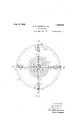
iVe accomplish these results in the manner set forth in the following specilication and illustrated in the accompanying drawing, in which Fifaure 1 is a, front elevation of t-he device with a portion cutaway in section `for the sake ot clearness. Figure 2 is a plan in which portions ot the rim-engaging hooks are cut away in section for the purpose of illustrating the operation of the two sets ot hooks.
Similar numbers and letters of reference refer to the same or similar parts throughout the views.
Referring.,r in detail to the drawings7 we have constructed our device of' a pedestal member 10 which is adapted to be secured to the floor. To the top of the pedestal 10 is secured a base 11 by means of the bolts 12. llotatably mounted in the center otn the base 11 is the vertical screw 13 whose lower end is shouldered and provided with a nut 14 which prevents it from bein; withdrawn 'from the base 11. Secured to the upper end ol the screw 13 is a hand wheel 15.
On the screw 13 is a nut 16 provided with Pour slots which are at right angles to each other. In each of these slots by means of the pins 17 is hinged a link 18 whose lower end is hinged by the pin 19 to the upper end of a vertical trame 20. A similar link 21 is joined to the lower end of the 'frame 20 by means of the pin 22.- The lower end or' the link 21 is hinged by means of the pin 23 within the slot 24 in the base 11. It will be understood that there are tour of these slots GEORGE R.
24 in the base 11: which correspond with the slots` in the nut 16.
A. lighter link 25 having the same llength as the link 21 and hingedbetween'thesame parts. il. and 20 'forms a parallelogram which tends to hold the 'frame 20 in a vertical position. y
ln the trames 2O we have-mounted the vertical rods 26 upon two oli-'which are rotatably placed the hooks 27 whose hook portions 28 are adapted to engage the edge ot a rim. The lower ends ot' the frames 20 are provided with the permanent hooks 29 and eX- tensions l0` 'tor supporting the tire itself when not held by the rim 31. The 'tace 32 is slightly irregular and is adapted to correspond with certain styles of rims now in the market. The faces 32 of the four trames 20 have the sam radii trom the axis of the screw 13. Upon the two remaining' rods We have placed the hooks 27A which are, however5 slightly shorter than are the hooks 27 tor reasons which will soon become apparent.
rllhe operation ot our device is as follows: lVhen desiring to remove a tire from the rim 31, it is placed in the position indicated in the drawings with its break 31A to one side ot the shorter hooks 27 A. The hooks 27 and 27A are now swung: around on the rods 26 and brought into engagement with the edge ot the rim 31. The opposite edge of the rim 31. which rests on the shoulder 20A of the trame 2O. is now in a position to be engag'ed by the hooks 29.
llt will be seen that any rotation of the hand wheel 15 which causes the nut 16 to rise will draw the four frames 20 toward the screw 18 and it will be observedv that the shorter hooks 27A will come into action first and break the rim at its joint before trying to compress same. This is a highly important feature in the construction of thisdevice. Then the hand wheel 15 has been sufficiently rotated, the tire will drop off and rest on the extensions 30.
1n order to mount a tire on the rim the operation is reversed. that' is. the nut 16 is forced downwards and the frames 20 outwardly so that the faces 32 press outwardly against the interior of the rim 31. It will be understood, of course, that in this operation it is not necessary for the hooks 27 and 27A to be engaged.
We are aware that various styles of devices have been produced to accomplish this purpose, we therefore do not claim this device broadly but only within the limits speciied in the following claims.
What we claim4 as new is:
l. In a trarne for tire changers, the come bination of a vertical frame member shaped to fit the inside of a rim and having a iixed outwardly projecting ,hook `formed on the lower end of said frame, with a vertical rod supported at both ends by said frame, a hook slidably and rotatably mounted on said rodbetween said supports above said fixed hook, and means for moving said frame inwardly and outwardly with relation to the rim.
2. In a tire changer, the combination of a pedestal, a base mounted on said pedestal, a vertical screw rotatably mounted on said base, a handwheel on the upper end of said screw,` a. nut on said screw between said hand wheel and base, four vertical frames diS- posed around said screw between said nut and base, pairs of toggle links hinging each frame to the nut and base, a parallelogram forming link parallel to and below the lower link ofeach pair of toggle links and hinged to the frame and base, a fixed hook projecting outwardly from each frame, a vertical rod secured on the outer side of each of said iframes, a hook slidably hinged on said rod above each fixed hook, one opposite pair ol said movable hooks being slightly nearer t0- gether than are the adjacent pair.
GEORGE R. HUDs'oN. FRANKLIN M. CULP.
Priority Applications (1)
| Application Number | Priority Date | Filing Date | Title |
|---|---|---|---|
| US502019A US1459303A (en) | 1921-09-20 | 1921-09-20 | Tire changer |
Applications Claiming Priority (1)
| Application Number | Priority Date | Filing Date | Title |
|---|---|---|---|
| US502019A US1459303A (en) | 1921-09-20 | 1921-09-20 | Tire changer |
Publications (1)
| Publication Number | Publication Date |
|---|---|
| US1459303A true US1459303A (en) | 1923-06-19 |
Family
ID=23995973
Family Applications (1)
| Application Number | Title | Priority Date | Filing Date |
|---|---|---|---|
| US502019A Expired - Lifetime US1459303A (en) | 1921-09-20 | 1921-09-20 | Tire changer |
Country Status (1)
| Country | Link |
|---|---|
| US (1) | US1459303A (en) |
Cited By (1)
| Publication number | Priority date | Publication date | Assignee | Title |
|---|---|---|---|---|
| FR2385547A1 (en) * | 1977-03-30 | 1978-10-27 | Caterpillar Tractor Co | APPARATUS AND METHOD FOR ASSEMBLING A PNEUMATIC ENCLOSURE AND A CENTRAL SUPPORT |
-
1921
- 1921-09-20 US US502019A patent/US1459303A/en not_active Expired - Lifetime
Cited By (1)
| Publication number | Priority date | Publication date | Assignee | Title |
|---|---|---|---|---|
| FR2385547A1 (en) * | 1977-03-30 | 1978-10-27 | Caterpillar Tractor Co | APPARATUS AND METHOD FOR ASSEMBLING A PNEUMATIC ENCLOSURE AND A CENTRAL SUPPORT |
Similar Documents
| Publication | Publication Date | Title |
|---|---|---|
| US1564496A (en) | Tire-removing mechanism | |
| US1459303A (en) | Tire changer | |
| US2697252A (en) | Tire retreading equipment | |
| US1948434A (en) | Automobile tire changing machine | |
| US2574195A (en) | Apparatus to expand and mount solid resilient tires on channelled wheels or rims | |
| US1729861A (en) | Device for removing rims from tires | |
| US2272231A (en) | Retreading vulcanizer | |
| US1824246A (en) | Tire removing machine | |
| US2077506A (en) | Adjustable rim | |
| US2424915A (en) | Vulcanizing apparatus | |
| US2597268A (en) | Machine for angularly guiding and mounting tires on wheels | |
| US3156289A (en) | Tire changing machine | |
| US1716882A (en) | Tire remover | |
| US2112440A (en) | Tire vulcanizer | |
| US2298602A (en) | Method of and apparatus for blocking hats | |
| US1793863A (en) | Tire changer | |
| US2228316A (en) | Tire recapping machine | |
| US1954031A (en) | Tire spreader | |
| US1443450A (en) | Wire reel | |
| US2888064A (en) | Circumferentially traveling type tire mounting device | |
| US1758264A (en) | Tire-changing machine | |
| US2024941A (en) | Retreading vulcanizer for tires | |
| US1715973A (en) | Method of and apparatus for manufacturing pneumatic tires | |
| US2440087A (en) | Tire recapping machine | |
| US1650674A (en) | Tire changer |