US1459139A - Weeder - Google Patents
Weeder Download PDFInfo
- Publication number
- US1459139A US1459139A US488316A US48831621A US1459139A US 1459139 A US1459139 A US 1459139A US 488316 A US488316 A US 488316A US 48831621 A US48831621 A US 48831621A US 1459139 A US1459139 A US 1459139A
- Authority
- US
- United States
- Prior art keywords
- weeding
- machine
- springs
- devices
- spool
- Prior art date
- Legal status (The legal status is an assumption and is not a legal conclusion. Google has not performed a legal analysis and makes no representation as to the accuracy of the status listed.)
- Expired - Lifetime
Links
- 238000009333 weeding Methods 0.000 description 26
- 241000196324 Embryophyta Species 0.000 description 14
- 239000002689 soil Substances 0.000 description 6
- 241000239290 Araneae Species 0.000 description 5
- 210000001520 comb Anatomy 0.000 description 3
- 230000003534 oscillatory effect Effects 0.000 description 2
- 241000234282 Allium Species 0.000 description 1
- 235000002732 Allium cepa var. cepa Nutrition 0.000 description 1
- 102000014160 PTEN Phosphohydrolase Human genes 0.000 description 1
- 108010011536 PTEN Phosphohydrolase Proteins 0.000 description 1
- 238000010276 construction Methods 0.000 description 1
- 230000003247 decreasing effect Effects 0.000 description 1
- 230000001105 regulatory effect Effects 0.000 description 1
- 238000007790 scraping Methods 0.000 description 1
- 241000894007 species Species 0.000 description 1
- 235000013311 vegetables Nutrition 0.000 description 1
Images
Classifications
-
- A—HUMAN NECESSITIES
- A01—AGRICULTURE; FORESTRY; ANIMAL HUSBANDRY; HUNTING; TRAPPING; FISHING
- A01B—SOIL WORKING IN AGRICULTURE OR FORESTRY; PARTS, DETAILS, OR ACCESSORIES OF AGRICULTURAL MACHINES OR IMPLEMENTS, IN GENERAL
- A01B39/00—Other machines specially adapted for working soil on which crops are growing
- A01B39/12—Other machines specially adapted for working soil on which crops are growing for special purposes, e.g. for special culture
- A01B39/18—Other machines specially adapted for working soil on which crops are growing for special purposes, e.g. for special culture for weeding
Definitions
- a crop to be weeded has its seed planted deeper than the weed seed, therefore, as the weeding .machine yieldably tills the soil, scraping the earth towards a row of growing-plants, the soil is well agitated and all sprouted weed seed and growing weeds are uprooted and cast aside.
- the machine by which such results are attained, has weeding members to encounter the row and weeds along the latter, as the machine is advanced, and provision is made for the proper clearing of the weeding members from lifted plants with as simple mechanism as possible in order to decrease the draft of the machine render it lighter and less complicated and make it more desirable for ordinary use.
- My invention further aims to provide a weeding machine wherein the weeding instrumentalities are supported to rotate about an axis at a right angle to the direction in which the machine is moved, and each weeding instrumentality is supported 50 that it may yield to a certain degree when engaging and uprooting weeds, but immediately after the weeding instrumentalities leave the soil there is a snap-like or sudden action of the weeding instrumentalities which causes the weeds held thereby to be discharged and the weeding instrumentalities cleaned.
- the construction entering into'this part of my invention is very important as it obviates the necessity of manually removing Weeds from the instrumentality and it is practically impossible for clods of earth and other matter to render the weeding instrumen- I talities inoperative. 1
- My invention further aims to provide a weeding machine having yieldable weeding members and novel means for regulating the yieldability of the members, which makes it possible for an operator to secure a strong,
- Fig. 2 is a side elevation of, the machine
- Fig. 3 is a cross sectional view of a portion of the machine, showing the oscillatory yieldable weeding devices, and
- Fig. 4 is a perspective view of one of devices.
- the reference numeral 1 denotes a substantially rectangular frame provided with bearings 2, and in said bears ings is journaled a shaft 3 having its ends provided with fixed traction wheels 4 so that when said wheels are moved over the ground, the shaft 3 will be revolved inits bearings.
- an extension 5 to which is connected'diverging and upwardly extending handle bars 6, said the 'handle bars being supported relative to the rear side of the frame 1 by braces 7 suitably secured to said handle bars and to the frame i 10 meshing with a largebeveled gear wheel p 11, mounted on the shaft 3, sothat the countershaft 9 may be driven when the machine is moved.
- the hub portion 12 of" a spider having radially disposed arms 13 and this spider is adapted to be revolved in a plane at a right angle to the longitudinal central plane of the machine.
- the outer ends of the spider arms 13 terminate in suitable ⁇ . bearings-.14. and stops. '15, as best; shown in Fig. 1.
- Pivotally supportedat the bearings 14 are detachable oscillatory and yieldable Weeding-,devices; each com-.:
- the support 18 is intermediate.
- the ring 21 hafs 'one sidef-thereof-pivoted-to the frame extension-5, as;at 28,- and the oppositeside ofthe ring is-atta ched to a rodorcable'29' extending to a handle of one of the -bars 6,
- tops of the plants-1 are Off'StlQh'fl nature-that thecomb tines may enter the plant top xvithout-itmaterially injuring the same.
- the frame 1 When moving theiweedingmachine from one place to another, the frame 1 is tilted, through the medium of the handle bars 6, so that the Weeding devices Will be supported above the ground and not: interfere With the movement of the machine.
- I One embodiment o1"? invention has been illustrated; but: it is to be “understood that the structural elements-are susceptibleto such variations andmodifications as fall Within thee-scope ofrtheappended claims.
Landscapes
- Life Sciences & Earth Sciences (AREA)
- Engineering & Computer Science (AREA)
- Mechanical Engineering (AREA)
- Soil Sciences (AREA)
- Environmental Sciences (AREA)
- Soil Working Implements (AREA)
Description
June 19, 1923. 1,459,139
R. G. BRUNER WEEDER Filed July 29 1921 W m unmmu I I- i? Patented June 19, 1923.
PTEN
' WEEDER.
Application filed July 29, 1921.- Serial No. 488,316.
T 0 all whom it may concern:
Be it known that I, REUBEN BRUNER, a citizen of the United States of America, residing at \Vindsor, in the county of Essex and Province of Ontario, Canada, have invented certain new and useful Improvements in lVeeders, of which the following is a speci fication, reference being had therein to the accompanying drawings. 1
In the operation of a weeding machine of the type herein disclosed, advantage is taken of the fact that the tops of the plants to be weeded, such as onions or the like, have few or no lateral offshoots in contradistinction to the weeds which usually have branching or bushing tops, so that the eeds are readily caught and lifted without disturbance of the plants themselves. Furthermore a crop to be weeded has its seed planted deeper than the weed seed, therefore, as the weeding .machine yieldably tills the soil, scraping the earth towards a row of growing-plants, the soil is well agitated and all sprouted weed seed and growing weeds are uprooted and cast aside. The cultivated plants. being rooted deeper and devoid of foliage, remain unharmed and are actually benefited by the cultivation.
The machine, by which such results are attained, has weeding members to encounter the row and weeds along the latter, as the machine is advanced, and provision is made for the proper clearing of the weeding members from lifted plants with as simple mechanism as possible in order to decrease the draft of the machine render it lighter and less complicated and make it more desirable for ordinary use.
My invention further aims to provide a weeding machine wherein the weeding instrumentalities are supported to rotate about an axis at a right angle to the direction in which the machine is moved, and each weeding instrumentality is supported 50 that it may yield to a certain degree when engaging and uprooting weeds, but immediately after the weeding instrumentalities leave the soil there is a snap-like or sudden action of the weeding instrumentalities which causes the weeds held thereby to be discharged and the weeding instrumentalities cleaned. The construction entering into'this part of my invention is very important as it obviates the necessity of manually removing Weeds from the instrumentality and it is practically impossible for clods of earth and other matter to render the weeding instrumen- I talities inoperative. 1
My invention further aims to providea weeding machine having yieldable weeding members and novel means for regulating the yieldability of the members, which makes it possible for an operator to secure a strong,
or weakresistance of the members when encountering the soil. This is essential on account of soil conditions and an operator may meet the varying requirements when necessary.
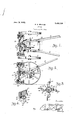
vMy invention will hereinafter be considered and then claimed,.and reference will now be had to the drawing, wherein Figure 1 is a plan of the weeding machine with the handle bars thereof' partly broken away; i i
Fig. 2 is a side elevation of, the machine;
Fig. 3 is a cross sectional view of a portion of the machine, showing the oscillatory yieldable weeding devices, and
Fig. 4 is a perspective view of one of devices.
In the drawing, the reference numeral 1, denotes a substantially rectangular frame provided with bearings 2, and in said bears ings is journaled a shaft 3 having its ends provided with fixed traction wheels 4 so that when said wheels are moved over the ground, the shaft 3 will be revolved inits bearings.
At the forward side of the. frame 1 isan extension 5 to which is connected'diverging and upwardly extending handle bars 6, said the 'handle bars being supported relative to the rear side of the frame 1 by braces 7 suitably secured to said handle bars and to the frame i 10 meshing with a largebeveled gear wheel p 11, mounted on the shaft 3, sothat the countershaft 9 may be driven when the machine is moved.
Suitably'mounted on the forward end of the countershaft 9 is the hub portion 12 of" a spider having radially disposed arms 13 and this spider is adapted to be revolved in a plane at a right angle to the longitudinal central plane of the machine. The outer ends of the spider arms 13 terminate in suitable}. bearings-.14. and stops. '15, as best; shown in Fig. 1. Pivotally supportedat the bearings 14 are detachable oscillatory and yieldable Weeding-,devices; each com-.:
prising a cross head 16, a comb 17, and a support 18. The support 18 is intermediate.
the ends of the cross head 16 and is pivota-lly supported at the bearings 14:- so that it may oscillate, but to maintain the cross head 16' normally in engagement with the I ofsaid springs may be increased or de creased, and for this purpose the spool 26 is engaged'by opposed studs27 of a pivoted ring 21 about the, spool 26. The ring 21 hafs 'one sidef-thereof-pivoted-to the frame extension-5, as;at 28,- and the oppositeside ofthe ring is-atta ched to a rodorcable'29' extending to a handle of one of the -bars 6,
sol thatlthe operator of A the Weeding machine 1 may, at Will, regulate the action or yieldability ofthe' Weeding members. permanent-ia dju'sting of the-springs maybe :attained-by providing -the-spool 26 with a screw 30, turningthe spoolzand then fixing The comb 17 has tines 22 projecting fromthe crosshead-16 and;th1e,body-or baclcof the-comb is :detacha-bly, connected to the cross-.
head bybolts- 23;and nuts 2 1, said bolts e:-:,-* tending through s1ots25 intheends of the I crosshe'ade Of 'course this-takes place after the combs. have loosened the weedsandthe action of Froma the foregoing it will be observed that-all of the combs are disposedain para1-..
1el longitudinalr planes Eand that the combs are successivelybrought: into action; With the spiderrevolving in :the direction indicated-aby the L arrow in-Fig- 3-, it is, possible 1 for the comb to yield; when. encountering theisoil, but-the .yielding.- of said comb places theiretractile springs 20 iunder additional tensiomso.thatfWhen the Weedsfare eventually; loosened. and uprooted and the: combleaves the soil, there will be a sudden and snap-like l action 30f 2 the same, -which jcauses theziweeds toa vbe discharged from, the comb.
the ioscillatory .weedingadevices not only dislodges :the. Weedsbut cast the: same: aside.
froiriggrowing; plants As pointed out in the be inning,- this:
Weeding .amachine-may beia vantageously used: iI1-'-1IGm0YiIlg--W68(1S fromrows of -such growing vegetables, as.i=0n1ons Where the;
tops of the plants-1 are Off'StlQh'fl nature-that thecomb tines may enter the plant top xvithout-itmaterially injuring the same. When moving theiweedingmachine from one place to another, the frame 1 is tilted, through the medium of the handle bars 6, so that the Weeding devices Will be supported above the ground and not: interfere With the movement of the machine. I One embodiment o1"? invention has been illustrated; but: it is to be "understood that the structural elements-are susceptibleto such variations andmodifications as fall Within thee-scope ofrtheappended claims.
hat I; "clailnis p 1. 111 a Weedingmachine,- Weeding -.devices, a spider-supporting said Weeding de vices, springs oonnectedgto said Weeding-dew vices and adapted to allow said Weeding devices to yield relative to said spider, and;
means connected to said springs. and mov-F- able co-axial of said spider for placing said.
springs unde'r: additional. tensionwhen ithen' Weeding devices encounter "deeply; rooted--,. WGQClSi 2.111 a-. Weeding machine having. yield-.1 able Weedingdevices-to which springsare at tachedto; permit of said devices' 1yielding:- means-for increasing. and :decreasingtheiten+ sion of said springs, said ;means comprising,
a slidable. spool -to which: said: springs are;
connected, and :means. operatabgle, from are. mote. point for slidingsaid ;spool-.
3., In a Weeding machine. having,- yieldable; Weeding rdevicesato wh-ich springs are.-
attached' to; permit: of esaid devicesiyielding:-means for increasing and decreasing; the tensionot said springs, said means comprising a slidablespolol toevhiich said springs; areiconnected; a pivot rin-g bout said-spool? d p edom e; da pooli'a da e asa e nected o a d" n s nd-svi pemtablee r a Y, distzn ce for! shifting said: ring and ad List-=5 ingsaid spool. I
-aw aga aa newhe e-in; d ng; ces;- r ppor e i e vo en apl n 'ati an angle to the direction in vvhich the rna-zeh ne s m ve xn ans for yi ldably holding saidweeding devices, said:means coirnprising-a slidable member springs conneet lng said devicesto. said member, and pivotal, means adapted- 'tQvfSlidQ said member '=to -,.inr crease; and decrease the tension of said? Swings. I In; testimony whereof I ;,-afiizX SigIlatELre, 1n P e e c of W Wi neS$ese w i ne ses;
IF JlYA.=--M- DQ153111 KARL-7H5
Priority Applications (1)
| Application Number | Priority Date | Filing Date | Title |
|---|---|---|---|
| US488316A US1459139A (en) | 1921-07-29 | 1921-07-29 | Weeder |
Applications Claiming Priority (1)
| Application Number | Priority Date | Filing Date | Title |
|---|---|---|---|
| US488316A US1459139A (en) | 1921-07-29 | 1921-07-29 | Weeder |
Publications (1)
| Publication Number | Publication Date |
|---|---|
| US1459139A true US1459139A (en) | 1923-06-19 |
Family
ID=23939240
Family Applications (1)
| Application Number | Title | Priority Date | Filing Date |
|---|---|---|---|
| US488316A Expired - Lifetime US1459139A (en) | 1921-07-29 | 1921-07-29 | Weeder |
Country Status (1)
| Country | Link |
|---|---|
| US (1) | US1459139A (en) |
-
1921
- 1921-07-29 US US488316A patent/US1459139A/en not_active Expired - Lifetime
Similar Documents
| Publication | Publication Date | Title |
|---|---|---|
| US2506054A (en) | Rotary beater topper for vegetable plants | |
| US1459139A (en) | Weeder | |
| US2882982A (en) | Cultivator for peanuts and the like | |
| US3106968A (en) | Combination weeding and cultivating attachment for a towing vehicle | |
| US1880113A (en) | Field conditioning machine | |
| US1249008A (en) | Tillage implement. | |
| US2804813A (en) | Tractor powered rotary cultivator | |
| US913953A (en) | Implement for hoeing and topping growing plants. | |
| US1257343A (en) | Boll-weevil exterminator. | |
| US1314394A (en) | Planoara | |
| US2492600A (en) | Weeder for potato harvesters and the like | |
| US2699713A (en) | Combination cultivator, chopper, and weeder | |
| US3066743A (en) | Rotary tilling device | |
| US2361605A (en) | Cultivator | |
| US787977A (en) | Plow attachment. | |
| US1144039A (en) | Cultivator. | |
| US1252627A (en) | Garden-tool. | |
| US2980190A (en) | Crop thinner | |
| US1795029A (en) | Power cotton chopper and tillage implement | |
| US2146337A (en) | Row cultivating implement | |
| US2560909A (en) | Rotary circular harrow | |
| US1065883A (en) | Disk cultivator. | |
| US1171263A (en) | Machine for setting plants. | |
| US3860075A (en) | Row crop rotary rod weeder | |
| US1047042A (en) | Harrow. |