US145504A - Improvement in cut-nail machines - Google Patents
Improvement in cut-nail machines Download PDFInfo
- Publication number
- US145504A US145504A US145504DA US145504A US 145504 A US145504 A US 145504A US 145504D A US145504D A US 145504DA US 145504 A US145504 A US 145504A
- Authority
- US
- United States
- Prior art keywords
- barrel
- blank
- knives
- knife
- jaws
- Prior art date
- Legal status (The legal status is an assumption and is not a legal conclusion. Google has not performed a legal analysis and makes no representation as to the accuracy of the status listed.)
- Expired - Lifetime
Links
- 238000010276 construction Methods 0.000 description 7
- 238000005520 cutting process Methods 0.000 description 5
- 230000001105 regulatory effect Effects 0.000 description 3
- 230000000630 rising effect Effects 0.000 description 3
- 238000005452 bending Methods 0.000 description 2
- 238000000926 separation method Methods 0.000 description 2
- 230000004308 accommodation Effects 0.000 description 1
- 229940000425 combination drug Drugs 0.000 description 1
- 230000000881 depressing effect Effects 0.000 description 1
- 230000003292 diminished effect Effects 0.000 description 1
- 210000003141 lower extremity Anatomy 0.000 description 1
- 239000002184 metal Substances 0.000 description 1
- 230000000153 supplemental effect Effects 0.000 description 1
Images


Classifications
-
- B—PERFORMING OPERATIONS; TRANSPORTING
- B21—MECHANICAL METAL-WORKING WITHOUT ESSENTIALLY REMOVING MATERIAL; PUNCHING METAL
- B21G—MAKING NEEDLES, PINS OR NAILS OF METAL
- B21G3/00—Making pins, nails, or the like
- B21G3/18—Making pins, nails, or the like by operations not restricted to one of the groups B21G3/12 - B21G3/16
- B21G3/26—Making pins, nails, or the like by operations not restricted to one of the groups B21G3/12 - B21G3/16 by cutting from strip or sheet material
-
- B—PERFORMING OPERATIONS; TRANSPORTING
- B21—MECHANICAL METAL-WORKING WITHOUT ESSENTIALLY REMOVING MATERIAL; PUNCHING METAL
- B21G—MAKING NEEDLES, PINS OR NAILS OF METAL
- B21G3/00—Making pins, nails, or the like
- B21G3/12—Upsetting; Forming heads
Definitions
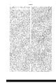
- Figure 1 is a perspective view of a machine for making tacks, 860., with my improvements applied thereto.
- Fig. 2 is a longitudinal vertical section through the center of the same.
- Fig. 3 is a plan of the under side.
- Fig. 4 is a rear elevation.
- Fig. 5 is a vertical section on the line 00 a; of Fig. 4.
- Fig. 6 is a horizontal section through the center of the heading-tool, representing it in a position to form the head of the tack when the blank is being held by the griping-dies.
- Fig. 7 is a vertical section on the line 3 y of Fig. 4.
- the eccentric or crank pin which actuates the headingtool is secured to the spindle outside of its bearing, being supported on one side only, and, owing to the immense strain to which the spindle is subjected at this point, it frequently'happens that it is cramped or broken from this cause.
- the object of the first portion of my invention which consists in extending the spindle and supporting the end so extended in an additional bearing situated outside the ordinary bearing, and attaching the pitman or connecting rod which actuates the heading-lever to the eccentric,
- My invention also consists in a balljoint formed in one and the same piece as the spindle, to which is hung the connecting-rod which moves the heading lever and tool, a joint or pivot so constructed admitting of the free lateral movement of the lower end of the connecting-rod, rendered necessary by the vibration of the heading-lever on its axis.
- My invention also consists in a mechanism for turning the barrel through which is fed the plate from which the blanks are cut, so as to bring the head of the blank always on the same side of the machine, being that next the heading-tool.
- My invention also consists in providingthe sides of the jaws which hold the cutters with lugs projecting out in front of the cutterstocks for the reception of screws, by which, in connection with other screws passing through the sides of the cutter-jaws, they are securely clamped, and prevented from moving laterally, their vertical adjustment being regulated by screws passing through projections at the tops of the jaws, by which construction the separation of the cutter-stocks, heretofore rendered necessary for the accommodation of the straps which held the cutters, and the bending of the stocks at their lower ends to bring the cutters together, are avoided, while the liability of the cutters springing and crowding against "each other, incident to the former construction, and which frequently resulted in their being drilled and broken, is also avoided, and I am enabled to use a narrower pair of
- My invention furthermore consists in a post or standard, which supports the outer end of the barrel through which the tack or nail plate is fed, pivoted in such manner that it may be swung down without disconnecting the barrel from the mechanism which rotates it, in order that the forward end of the barrel may be withdrawn and moved to one side of the knives for the purpose of removing them and the dies when they require to be sharpened and repaired.
- My invention also consists in the combina tion, with a bifurcated or bridge-shaped holder for the reception of the ends of the springs, of hollow jaws for the passage of said springs, the resistance of which keeps the jaws constantly up in contact with the under sides of the cams on the driving-shaft, whereby a regular and positive motion of the vertical knives is insured and the space occupied is economized.
- A is the driving-shatt or spindle, to one end of which is secured a balance-wheel, I for equalizing its motion, the opposite end of the spindle having a pinion, a, secured thereto, and being supported in three bearings,1t 15 16, in the-framework 17, for a purpose to be mentioned hereafter.
- This pinion drives a cog-whcel, 0, on a short shaft, 1), provided with a bcarin g, 18, extend ing its entire length, and carrying a disk, D, to which, near its periphery, is secured the upper end of av connecting-rod, E, having its lower end secured to a rocker-arm, c, on a shaft, Gr, vibrated in bearings 19, fastened to the under side of the frame-work.
- rocker-arm to which is secured one end of a long red, H, the opposite end of which is made to engage with the crank-pin 20 of a crank, 0, secured to a short shaft, 21, having 22 secured to the under side of a long bar, I, extending out nearly horizontally from the frame-work, to which its inner end when adjusted by screws 2+ passing through lugs 25 projecting from the frame-work.
- 26 is a hook extending down from the bar I, for supporting the rod H when disconnected from its crank-pin 20.
- the short shaft 21 moves two rocker-arn1s,f one on each side of the bar, and outside the bearings 22, each rockerarm having secured to its outer end the lower extremity of one of a pair of straps, It, the upper end of which is attached to one of a pair ofcollars, 45, which are clamped by screws 27 to the longitudinal barrel or tube K, through which the metal plate or strip to form the tack or nail is guided as it is fed forward to the severing point by nippers connected with a weight, not shown.
- the outer end of the barrel or tube K is supported in a post or standard, L, rising from the outer end of the bar I, the barrel also passing under a semicircular spring-guide, 28, attached to suitable braces, 29 30, secured to the upper side of the framework;
- the inner end of the barrel through which. the tack or nail plate is fed is provided with a slotted finger, k, which serves as a guide for properly directing the inner end of the plate to the cutting-point, two bent springar1ns, 31, secured to the upper side of the frameone on each side of the plate-being also provided as additional means of securing the accurate delivery of the plate to the point where the blanks are severed.
- the butt-end of each of these arms 31 is provided with a slotted finger, k, which serves as a guide for properly directing the inner end of the plate to the cutting-point, two bent springar1ns, 31, secured to the upper side of the frameone on each side of the plate-being also provided as additional means of securing the accurate delivery of
- the inner diameter of the barrel should correspond with the width of the plate to be fed through it; consequently, where plates of different widths are to be cut up in one and the same machine, barrels of diameters to correspond.
- the slotted finger-guide k rests 011 a knife, I, having its edge slightly inclined upward, and placed upon the die m, which gripes the blank when it is being struck to form the head of the tack, both the knife I and the die m being sit uated in an inclined stationary bed, 2, formed in the upper side of the front of the framework, and being adjusted laterally therein by loosening one set and tightening the opposite set of screws a 33, which pass through the side of the bed, the two lower screws, 0/, turning against and moving the die on in the stationary bed, and the two upper screws, 33, turning against and moving the knife Z therein, the longitudinal adjustment of the knife land die m in their bed being effected by operating the screws 34 and 35, respectively.
- I11 order to remove the knife I and die m, as well as the upright movable knives, (presently to be described,) without disconnecting the barrel K from its straps h whenever the die and knives are dull and require to be sharpened, I construct the post or support L in two pieces, at 0, the .upper piece, a, of which is pivoted, at 36, to a short stud, 37, rising from the lower piece 0, this stud being provided with a notch or recess, 38, into which catches a projection, 39, formed near the lower end of a spring-plate, 40, which is secured at its top to the upper piece, a, of the post, by which arrangement the spring-plate may be pressed away from the post, so as to withdraw the projection 39 from its recess 38, when the upper piece, a, is free to be swung out on' its pivot, thus allowing the outer cnd of the barrel to fall into a position to admit of the slotted fin gergnide k being placed to one side of the knife I to
- p q are the severingknives, placed in recesses formed in the heads of hollow jaws M N, the knife 19 being placed in the jaw M, which projects up from a horizontal shaft, 0, extending transversely between the sides of the frame-work, and hung on pivots 41 passing into each end of it.
- the knife (1 is placed on the jaw N, projecting up from a similar shaft, P, hung on pivots 42.
- both of these knives are snugly held in contact with each other by screws 43 44 passing through the sides of the jaws, the lateral adjustment of the knives being regulated thereby.
- the longitudinal adj ustment of these knives is effected by operating-screws 45 46 passing through projections 47 48, extending from the topsof the heads of the jaws over the recesses in which the knives are situated.
- the jaws are provided with lugs r (projecting out iir front of the cutter-stocks) for the reception of screws I1 for securely holding the cutters in place,
- the jaws though pivoted independently, have their movements so timed with respect to each other, by means of the cams O P, for depressing them, as to cause both knives p q to operate simultaneously in cutting through the plate, the two edges of the knives acting as one continuous edge till the blank is severed, the edge of the knife 1? cutting from the point of the blank to where the continually-enlarging portion is to be upset to form the head of the tack.
- Each jaw M N is made hollow for the reception of a stiff spring, 8, the inner upper end of which bears up against the under side of a frictionroll, 48, having its bearings in the interior of the head of the jaw, by which means the springs exert a constant pressure to keep the jaws in contact with the cams 0 P on the shaft A, the revolution of the latter causing the cams to periodically depress the jaws and their knives, to cut the plate against the resistance of the springs.
- the outer ends of the springs are securely confined, by screws 49, within openings 50, formed in a bifurcated or bridge-shaped holder, Q, secured to the back of the framework.
- a portion of the cam O and a corresponding portion of the cam l are exactly of the same diameter, in order to insure the uniform and simultaneous descent of greater portion of its length.
- T is a bifurcated lever, pivoted, at 54, to the inside of the frame-work, and provided with a recess near its center for the reception of the die S, which is adjusted laterally an d longitudinally therein by operating screws 55 56.
- v From one side of this lever T rises a strong arm, U, the upper end of which is kept constantly in contact with a cam, V, on the shaft A by a rod, 57, connected with the upper end of a spring, 58, secured at its lower ends to the framework, by which construction the lever T is vibrated to insure the periodical advance of the die S to grasp the blank, as required.
- an eccentric which serves as a ball-joint, 59, for the upper end of a pitman or connect-ing rod, X, to move upon, the lower end of this rod X being pivoted, at 60, within the open slotted end of a bent portion of the heading-lever, Y, pivoted to the frame-work at 61.
- the upper side of the headinglever is provided with a longitudinal opening for the reception of a long bar or heading-tool, Z, which performs the office of upsetting the head of the blank, and is of about the same width as the opening, and is, like it, rectangular in cross-section throughout the
- This headingtool is kept from playing vertically in its seat by means of a screw, 62, passing through a bridge-piece, 63, and against the upper side of the headin g-tool, the longitudinal adjustment of which, to regulate the distance of its throw forward, being effected by a screw, 64.
- the heading-lever is vibrated so as to bring the heading-tool Z forcibly up against thehea-d of the blank to upset it, to form the head of the tack or nail, as required, after which the gripingdies and the heading-tool withdraw to their normal position, leaving the tack or nail free to fall into a hopper (not shown) placed to receive it.
- the plate is turned by the rotation of the barrel immediately before the vertical knives p q have risen above the level of the edge of the knife I, confined in the stationary bed 2, the end of the plate bearing against the vertical knives p q until they have risen sufficiently to admit of the plate being again fed forward by the action of the weight on the nippers, previ ously referred to, the operations of cutting the blank and forming the tack or nail being continued, as before described.
- the supplemental bifurcated support 16 constructed and arranged, as described, for supporting the shaft A, in combination with the shaft A, the support 15, rod X, and eccentric for operating the lever Y of the headingtool Z, substantially as set forth.
- the post L made in two pieces, a and 0, hinged at 36 37, and having a recess, 38, in combination with the spring 40, having a projection, 39, whereby I am enabled to throw back the barrel K without removing the straps, as described.
- the adjustable hollow or channeled jaws M N provided with lugs 1' 1 extending in front of, but not bridging over, the knives p q, substantially as and for the purpose set forth.
Landscapes
- Engineering & Computer Science (AREA)
- Mechanical Engineering (AREA)
- Perforating, Stamping-Out Or Severing By Means Other Than Cutting (AREA)
Description
3 Sheets--Sheet1.
E. A'. KIMBALL. Gut-Nail Machines Patented Dec. 16,1873.
3 Sheets--Sheet 2.
E. A. KIMBALL. Cut-Nail Machines 7 PM u fin m e D d e M. m M A e z .w w
4 0 5 1 5 m o N UNITED STATES PATENT OFFICE.
BEEN A. KIMBALL, OF ABINGTON, MASSACHUSETTS, ASSIGNOR TO HIMSELF, JOSEPH E. KIMBALL, AND EDWD. MERRITT, OF SAME PLACE.
IMPROVEMENT IN CUT-NAIL MACHINES.
Specification forming part of Letters Patent No. 145,504, dated December 16, 1873; application filed July 31, 1873.
To all whom it may concern.-
Be it known that I, EBEN A. KIMBALL, of Abington, in the county of Plymouth and State of Massachusetts, have invented certain Improvements in Machines for Making Tacks and Nails, of which the following is a full,
clear, and exact description reference being had to the accompanying drawings makingpart ot this specification, in which Figure 1 is a perspective view of a machine for making tacks, 860., with my improvements applied thereto. Fig. 2 is a longitudinal vertical section through the center of the same. Fig. 3 is a plan of the under side. Fig. 4 is a rear elevation. Fig. 5 is a vertical section on the line 00 a; of Fig. 4. Fig. 6 is a horizontal section through the center of the heading-tool, representing it in a position to form the head of the tack when the blank is being held by the griping-dies. Fig. 7 is a vertical section on the line 3 y of Fig. 4.
In machines for making tacks and nails, as heretofore constructed, the eccentric or crank pin which actuates the headingtool is secured to the spindle outside of its bearing, being supported on one side only, and, owing to the immense strain to which the spindle is subjected at this point, it frequently'happens that it is cramped or broken from this cause.
To obviate these difiiculties and to provide smaller bearing-surfaces, and thereby reduce the friction thereon, is the object of the first portion of my invention, which consists in extending the spindle and supporting the end so extended in an additional bearing situated outside the ordinary bearing, and attaching the pitman or connecting rod which actuates the heading-lever to the eccentric,
between the two, whereby additional support is provided, and. increased strength and freedom of motion insured, while at the same time a lighter balance-wheel may be used for equalizing the motion of the machine, and for overcoming the resistance encountered in heading the blank while being held by the dies. My invention also consists in a balljoint formed in one and the same piece as the spindle, to which is hung the connecting-rod which moves the heading lever and tool, a joint or pivot so constructed admitting of the free lateral movement of the lower end of the connecting-rod, rendered necessary by the vibration of the heading-lever on its axis. My invention also consists in a mechanism for turning the barrel through which is fed the plate from which the blanks are cut, so as to bring the head of the blank always on the same side of the machine, being that next the heading-tool. My invention also consists in providingthe sides of the jaws which hold the cutters with lugs projecting out in front of the cutterstocks for the reception of screws, by which, in connection with other screws passing through the sides of the cutter-jaws, they are securely clamped, and prevented from moving laterally, their vertical adjustment being regulated by screws passing through projections at the tops of the jaws, by which construction the separation of the cutter-stocks, heretofore rendered necessary for the accommodation of the straps which held the cutters, and the bending of the stocks at their lower ends to bring the cutters together, are avoided, while the liability of the cutters springing and crowding against "each other, incident to the former construction, and which frequently resulted in their being drilled and broken, is also avoided, and I am enabled to use a narrower pair of jaws, thus economizing space. My invention furthermore consists in a post or standard, which supports the outer end of the barrel through which the tack or nail plate is fed, pivoted in such manner that it may be swung down without disconnecting the barrel from the mechanism which rotates it, in order that the forward end of the barrel may be withdrawn and moved to one side of the knives for the purpose of removing them and the dies when they require to be sharpened and repaired. My invention also consists in the combina tion, with a bifurcated or bridge-shaped holder for the reception of the ends of the springs, of hollow jaws for the passage of said springs, the resistance of which keeps the jaws constantly up in contact with the under sides of the cams on the driving-shaft, whereby a regular and positive motion of the vertical knives is insured and the space occupied is economized.
To enable others skilled in the art to under- 1 its bearings stand and use my invention, I will proceed to describe the manner in which I have carried it out.
In the said drawings, A is the driving-shatt or spindle, to one end of which is secured a balance-wheel, I for equalizing its motion, the opposite end of the spindle having a pinion, a, secured thereto, and being supported in three bearings,1t 15 16, in the-framework 17, for a purpose to be mentioned hereafter. This pinion drives a cog-whcel, 0, on a short shaft, 1), provided with a bcarin g, 18, extend ing its entire length, and carrying a disk, D, to which, near its periphery, is secured the upper end of av connecting-rod, E, having its lower end secured to a rocker-arm, c, on a shaft, Gr, vibrated in bearings 19, fastened to the under side of the frame-work. About midway between the bearings 1!) is another rocker-arm, d, to which is secured one end of a long red, H, the opposite end of which is made to engage with the crank-pin 20 of a crank, 0, secured to a short shaft, 21, having 22 secured to the under side of a long bar, I, extending out nearly horizontally from the frame-work, to which its inner end when adjusted by screws 2+ passing through lugs 25 projecting from the frame-work. 26 is a hook extending down from the bar I, for supporting the rod H when disconnected from its crank-pin 20. The short shaft 21 moves two rocker-arn1s,f one on each side of the bar, and outside the bearings 22, each rockerarm having secured to its outer end the lower extremity of one of a pair of straps, It, the upper end of which is attached to one of a pair ofcollars, 45, which are clamped by screws 27 to the longitudinal barrel or tube K, through which the metal plate or strip to form the tack or nail is guided as it is fed forward to the severing point by nippers connected with a weight, not shown. The outer end of the barrel or tube K is supported in a post or standard, L, rising from the outer end of the bar I, the barrel also passing under a semicircular spring-guide, 28, attached to suitable braces, 29 30, secured to the upper side of the framework; The inner end of the barrel through which. the tack or nail plate is fed is provided with a slotted finger, k, which serves as a guide for properly directing the inner end of the plate to the cutting-point, two bent springar1ns, 31, secured to the upper side of the frameone on each side of the plate-being also provided as additional means of securing the accurate delivery of the plate to the point where the blanks are severed. The butt-end of each of these arms 31. is provided with a slot for the passage of a screw, 32, in order that their 'bent ends may be adjusted nearer to or farther from each other to accommodate tack or nail plates of different widths. The inner diameter of the barrel should correspond with the width of the plate to be fed through it; consequently, where plates of different widths are to be cut up in one and the same machine, barrels of diameters to correspond.
are required; and as these plates must be turned over after each successive blank has been separated therefrom, in order that the larger end, which is to form the head of the tack, be presented always on one and the same side, being that next the heading-tool, a suitable means of regulating the throw of the various-sized barrels becomes necessary, which I provide by employing collars having the same unvarying exterior diameter fitting over the several barrels required for plates of different widths, the interior diameter of the collar and the exterior diameter of each barrel being carefully made to fit each other, by
which construction no change of the straps h is rendered necessary. In the event of the slotted finger-guide k being either too long or too short, so as to turn too much or not enough to leave the plate flat or horizontal 'at the proper time for severing the blank, I adjust the throw of the barrel, and consequently the said slotted guide, by slipping the collars around on the barrel in opposite directions, and clamping them thereon by the screws 27, whereby the efiective length of one strap is increased, and that of the other diminished, to insure the accurate timing of the throw of the barrel. The slotted finger-guide k, at the inner end of the barrel, rests 011 a knife, I, having its edge slightly inclined upward, and placed upon the die m, which gripes the blank when it is being struck to form the head of the tack, both the knife I and the die m being sit uated in an inclined stationary bed, 2, formed in the upper side of the front of the framework, and being adjusted laterally therein by loosening one set and tightening the opposite set of screws a 33, which pass through the side of the bed, the two lower screws, 0/, turning against and moving the die on in the stationary bed, and the two upper screws, 33, turning against and moving the knife Z therein, the longitudinal adjustment of the knife land die m in their bed being effected by operating the screws 34 and 35, respectively.
I11 order to remove the knife I and die m, as well as the upright movable knives, (presently to be described,) without disconnecting the barrel K from its straps h whenever the die and knives are dull and require to be sharpened, I construct the post or support L in two pieces, at 0, the .upper piece, a, of which is pivoted, at 36, to a short stud, 37, rising from the lower piece 0, this stud being provided with a notch or recess, 38, into which catches a projection, 39, formed near the lower end of a spring-plate, 40, which is secured at its top to the upper piece, a, of the post, by which arrangement the spring-plate may be pressed away from the post, so as to withdraw the projection 39 from its recess 38, when the upper piece, a, is free to be swung out on' its pivot, thus allowing the outer cnd of the barrel to fall into a position to admit of the slotted fin gergnide k being placed to one side of the knife I to remove it and the other knives and die m for the purpose of sharpening them, or
when it is required to substitute other knives or dies therefor, thus obviating the necessity of detaching the straps h from the barrel or the rocker-arms f g. p q are the severingknives, placed in recesses formed in the heads of hollow jaws M N, the knife 19 being placed in the jaw M, which projects up from a horizontal shaft, 0, extending transversely between the sides of the frame-work, and hung on pivots 41 passing into each end of it. The knife (1 is placed on the jaw N, projecting up from a similar shaft, P, hung on pivots 42. The inner surfaces of both of these knives are snugly held in contact with each other by screws 43 44 passing through the sides of the jaws, the lateral adjustment of the knives being regulated thereby. The longitudinal adj ustment of these knives is effected by operating-screws 45 46 passing through projections 47 48, extending from the topsof the heads of the jaws over the recesses in which the knives are situated. The jaws are provided with lugs r (projecting out iir front of the cutter-stocks) for the reception of screws I1 for securely holding the cutters in place,
when correctly adjusted, by which arr ngement the cutters remain in contact with each other throughout their entire length, no separation of their stocks or bending of their lower or cut ting edges, incident to the former construction, where straps were employed for holding them, being required, and all liability of the cutters being injured or broken by their springing and crowding together being avoided, while, at the same time, a narrower pair of jaws may be employed, which not only economizes space, but simplifies and reduces the cost of construction. The jaws, though pivoted independently, have their movements so timed with respect to each other, by means of the cams O P, for depressing them, as to cause both knives p q to operate simultaneously in cutting through the plate, the two edges of the knives acting as one continuous edge till the blank is severed, the edge of the knife 1? cutting from the point of the blank to where the continually-enlarging portion is to be upset to form the head of the tack. Each jaw M N is made hollow for the reception of a stiff spring, 8, the inner upper end of which bears up against the under side of a frictionroll, 48, having its bearings in the interior of the head of the jaw, by which means the springs exert a constant pressure to keep the jaws in contact with the cams 0 P on the shaft A, the revolution of the latter causing the cams to periodically depress the jaws and their knives, to cut the plate against the resistance of the springs. The outer ends of the springs are securely confined, by screws 49, within openings 50, formed in a bifurcated or bridge-shaped holder, Q, secured to the back of the framework. A portion of the cam O and a corresponding portion of the cam l are exactly of the same diameter, in order to insure the uniform and simultaneous descent of greater portion of its length.
the knives p (1 while cutting the plate, after which the remaining enlarged portion of the cam P revolves in' contact with and depresses the jaw N still lower, causing its knife (1 to be carried below the plane where the blank was severed, and below the edge of the knife 19, which temporarily remains at rest, the knife q pressing the larger end of the blank down up-.
on the point of a curved bearer, f, securely clamped in a standard, It, rising from an arm, 51, projecting from the frame-work. The surface of the standard on which the bearer is clamped is of such extent that it acts as a spring, being carried down by the descent of the knife, so as to hold the head of the blank between them till the moving die S (presently to be described) is advanced toward the die m to grasp and form the shank portion of the tack, after which, and while the shank portion of the tack is being held by the dies, the knife q and the spring-bearer t separate, thus releasing their hold of the head of the blank, the knife q being carried, by the pressure of the springs on the fri'ctioirroll 48, within thehead of its jaw, and the point of the spring-bearer being pressed laterally from under the head of the blank by the lower end of a lever, 52, pivoted, at 53, to the frame-work, the upper end of this lever being pressed forward by a cam, u, on the spindle, which revolves it in contact therewith, and throws the lower end of the lever against the bearer, moving it to one side, as described.
The die S derives its motion in the following manner: T is a bifurcated lever, pivoted, at 54, to the inside of the frame-work, and provided with a recess near its center for the reception of the die S, which is adjusted laterally an d longitudinally therein by operating screws 55 56. v From one side of this lever T rises a strong arm, U, the upper end of which is kept constantly in contact with a cam, V, on the shaft A by a rod, 57, connected with the upper end of a spring, 58, secured at its lower ends to the framework, by which construction the lever T is vibrated to insure the periodical advance of the die S to grasp the blank, as required.
I will now describe the construction and operation of the heading-tool. Between the bearings 15 and 16 of the shaft, and in one and the same piece therewith, is formed an eccentric, which serves as a ball-joint, 59, for the upper end of a pitman or connect-ing rod, X, to move upon, the lower end of this rod X being pivoted, at 60, within the open slotted end of a bent portion of the heading-lever, Y, pivoted to the frame-work at 61. The upper side of the headinglever is provided with a longitudinal opening for the reception of a long bar or heading-tool, Z, which performs the office of upsetting the head of the blank, and is of about the same width as the opening, and is, like it, rectangular in cross-section throughout the This headingtool is kept from playing vertically in its seat by means of a screw, 62, passing through a bridge-piece, 63, and against the upper side of the headin g-tool, the longitudinal adjustment of which, to regulate the distance of its throw forward, being effected by a screw, 64. After the knife (1 and spring-bearer t have released their hold on the head of the blank, and have withdrawn from the path of the hcading'tool, and while the griping-dies are still holding the shank of the tack or nail just formed by them, the heading-lever is vibrated so as to bring the heading-tool Z forcibly up against thehea-d of the blank to upset it, to form the head of the tack or nail, as required, after which the gripingdies and the heading-tool withdraw to their normal position, leaving the tack or nail free to fall into a hopper (not shown) placed to receive it. The plate is turned by the rotation of the barrel immediately before the vertical knives p q have risen above the level of the edge of the knife I, confined in the stationary bed 2, the end of the plate bearing against the vertical knives p q until they have risen sufficiently to admit of the plate being again fed forward by the action of the weight on the nippers, previ ously referred to, the operations of cutting the blank and forming the tack or nail being continued, as before described.
What I claim as my invention, and desire to secure by Letters Patent, is-- 1. The supplemental bifurcated support 16, constructed and arranged, as described, for supporting the shaft A, in combination with the shaft A, the support 15, rod X, and eccentric for operating the lever Y of the headingtool Z, substantially as set forth.
2. The ball-joint, 59, formed in one and the same piece as the shaft A, in combination with the connecting-rod X for operating the lever Y of the heading-tool Z, substantially as and for the purpose set forth.
3. The shafts G 21, with their rocker arms 0 df g, in combination with the disk D, rods E H, crank e, and straps h h, with or without the adjustable collars i, for rotating the barrel K, through which the plate is fed, substantially as described.
4. The post L, made in two pieces, a and 0, hinged at 36 37, and having a recess, 38, in combination with the spring 40, having a projection, 39, whereby I am enabled to throw back the barrel K without removing the straps, as described.
5. The adjustable hollow or channeled jaws M N, cast, as described, so as to form ways, in combination with the springs s s and bifurcated holder Q. I
6. The adjustable hollow or channeled jaws M N, provided with lugs 1' 1 extending in front of, but not bridging over, the knives p q, substantially as and for the purpose set forth.
Vitness my hand this 28th day of July, A. D. 1873.
EBEN A. KIMBALL.
In presence of-'- BELU THAXTER, J. F. FRENCH.
Publications (1)
| Publication Number | Publication Date |
|---|---|
| US145504A true US145504A (en) | 1873-12-16 |
Family
ID=2214918
Family Applications (1)
| Application Number | Title | Priority Date | Filing Date |
|---|---|---|---|
| US145504D Expired - Lifetime US145504A (en) | Improvement in cut-nail machines |
Country Status (1)
| Country | Link |
|---|---|
| US (1) | US145504A (en) |
-
0
- US US145504D patent/US145504A/en not_active Expired - Lifetime
Similar Documents
| Publication | Publication Date | Title |
|---|---|---|
| US145504A (en) | Improvement in cut-nail machines | |
| US196869A (en) | Imp rove me nt in cut-nail machines | |
| US414002A (en) | Horn for can-machines | |
| US458391A (en) | Wire-nail machine | |
| US658766A (en) | Hand lasting-tool. | |
| US309255A (en) | Wire nail machine | |
| US313108A (en) | Nail-machine | |
| US246933A (en) | worsley | |
| US355610A (en) | Tack machine | |
| US378656A (en) | Nail-making machine | |
| US341658A (en) | Nail-machine | |
| US31949A (en) | Machine for making butt-hinges | |
| US22837A (en) | Improved machine for shaving the heads of screw-blanks | |
| US583420A (en) | Half to rodolphtjs c | |
| US354980A (en) | hersey | |
| US85478A (en) | Improvement in nail-plate feeders | |
| US58520A (en) | whittemore | |
| US55722A (en) | Improvement in nail-plate feeders | |
| US309446A (en) | Wire-nail machine | |
| USRE685E (en) | Improvement in machinery for making wood-screws | |
| US631677A (en) | Machine for cutting circular disks for buttons or the like. | |
| US483085A (en) | Attachment fob cut nail machines | |
| US355609A (en) | Nail-machine | |
| US569554A (en) | And lynn | |
| US413937A (en) | hansen |