US1440826A - Electrical heating element for pressure cookers - Google Patents
Electrical heating element for pressure cookers Download PDFInfo
- Publication number
- US1440826A US1440826A US432294A US43229421A US1440826A US 1440826 A US1440826 A US 1440826A US 432294 A US432294 A US 432294A US 43229421 A US43229421 A US 43229421A US 1440826 A US1440826 A US 1440826A
- Authority
- US
- United States
- Prior art keywords
- channel
- heating element
- cover
- container
- electrical heating
- Prior art date
- Legal status (The legal status is an assumption and is not a legal conclusion. Google has not performed a legal analysis and makes no representation as to the accuracy of the status listed.)
- Expired - Lifetime
Links
- 238000010438 heat treatment Methods 0.000 title description 28
- 239000007788 liquid Substances 0.000 description 4
- 239000002184 metal Substances 0.000 description 4
- 239000004020 conductor Substances 0.000 description 2
- 238000010276 construction Methods 0.000 description 2
- 238000009835 boiling Methods 0.000 description 1
- 229910052729 chemical element Inorganic materials 0.000 description 1
- 238000010586 diagram Methods 0.000 description 1
- 230000005611 electricity Effects 0.000 description 1
- 238000002474 experimental method Methods 0.000 description 1
- 239000011810 insulating material Substances 0.000 description 1
- 239000000463 material Substances 0.000 description 1
- 239000010445 mica Substances 0.000 description 1
- 229910052618 mica group Inorganic materials 0.000 description 1
- 238000009827 uniform distribution Methods 0.000 description 1
- XLYOFNOQVPJJNP-UHFFFAOYSA-N water Substances O XLYOFNOQVPJJNP-UHFFFAOYSA-N 0.000 description 1
Images

Classifications
-
- A—HUMAN NECESSITIES
- A47—FURNITURE; DOMESTIC ARTICLES OR APPLIANCES; COFFEE MILLS; SPICE MILLS; SUCTION CLEANERS IN GENERAL
- A47J—KITCHEN EQUIPMENT; COFFEE MILLS; SPICE MILLS; APPARATUS FOR MAKING BEVERAGES
- A47J27/00—Cooking-vessels
- A47J27/004—Cooking-vessels with integral electrical heating means
Definitions
- nvnanr'r e. HAGER, or KIMBERLY, IDAHO, Assmnon or ONE-HALF To s'runn'r B.
- -" lh's invention relates to pressure cookers and has special reference to that type of cooker that employs an electric heater ele ment for the generation or the heat required for its operation.
- the object of this invention to so relate the heater element to the device to which it is attached that there will be a good heat conducting path from both sides of the heating element to the liquid or other object to .be heated. It is also my object to so design and relate the parts that there will be a uniform distribution of heat over the entire surface of the heater, or in this case over the entire bottom of the cooker. It is also my object to provide means whereby the quantity of heat generated per unit of time may be varied to suit the conditions under which the cooker is operated, in this manner heat "may be generated at a high rate until the proper temperature and pressure are attained and thereafter the rate may be made smaller, thus enabling the device to be operated ata high thermal efficiency.
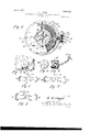
- FIG. 1 is a side elevation of myimproved pressure cooker with parts'broken away to show the location of my heating element.
- Fig. 2 is a fragmentary sectional view showing the methodof joining the heat coils view with parts Figs. 7, 8 and 9 are diagrams of connections showing the various combinations that can be madewith the. heating elements.
- a pressure cooker comprising the body part 1 and the cover 2.
- the cover is provided with a downwardly extending tapering gfiange 3 and outwardly projecting lugs 4: in which are notches 5 for the reception of a clamping bolt 6 having a butterfly nut 7.
- the body portion has a plurality of sets of outwardly extending spaced lugs 8 to which bolts 6 are pivotally attached by means of a rivet 9.
- the cover is firmly clamped to the container by means of the bolt 6 and butterfly! nuts 7' whereby the tapering flange forms a steam tight fit.
- the cover is provided with the usual pressure gage 10 and safety valve 11.
- the container and cover maybe of any conventional design as it forms no part of my invention except in so far as l have modified the bottom of the container so as to adapt it for-the reception of my heating element.
- This construction results in a substantial structure and provides a good heat con ducting path from ring 14; to the body of the container; this is of great importance as it prevents thelower side of the heating element from becoming over heated and also helps to distribute the heat evenly over the bottom or the container.
- Extensive tests have shown that when the heating element isenclosed in the manner described above all it will not burn out evenwhen the container is dry and water w ll boil equally well on every part of the bottom of the container distinguished from containers which are not provided with the embedded heating elemerit, in these latter the boiling will usually be more violent directly above the heating element.
- notch 23 extends from channel 13 to the outside of the container.
- the annular cover ring llis provided with a projection 2a which serves to cover this notch in the manner shown in Fig. 2.
- a cup-like structure 26 Secured to the outside of the container and held in place'thereon by means of screws 25 is a cup-like structure 26 having a downwardly projecting portion which comprises two parts 27 which are located against the sides of the container and which are joined by an outwardly curved centralportion 28 which cooperates with the extending portion 24: of ring 14 to form a closed channel for leads 29, 30 and 31 from heat coils 4:0 and a l to contact terminals 32, 33 and 34 respectively; these terminals are insulated from the cup-shaped structure 26 by means of insulating washers 35, as shown in Fig. 3.
- 29 is a common lead from the corresponding ends or both or the heating coils connecting them with terminal 32;
- the other ends of the coils being each connected to one of terminals 33 and 3% by conductors 30 and 31.
- the current is supplied from wires 36 and 37 throu h a plug 38 having three socket contacts M and T spaced equidistantly so that they will engage with terminals 32, 33
- Sockets L and M are connected by ajumper 39.-
- Tt we make connections in the manner inraraeae degrees of heat and permits the device to be used economically.
- T have shown my heater enibodied in the structure of a pressure coolrer T desire to point out that T consider that my invention is broader than this and that the principle employed can be utilized in the construction of heating elements for other purposes.
- the heating element By having the heating element'enclosed in a channel provided with a removable cover, it can be readily renewed and replaced in case it burns out or deteriorates for any'other reason. l fe therefore get the advantages of a cast in element with the additional advantage of having the heater element readily renewable.
- An electric heater comprising a plate of metal having a shallow channel therein, a fiat heating element in said channel, a removable metal cover for said channel, said cover being slightly wider thanthe channel and adapted to be clamped firmly against the heating element, and means for conducting electricity to said heating element.
- An electric heater comprising a metal plate having a shallow annular channel in one side thereof, ring shaped flat heating elements in said channel, a cover for said channel comprising an annular member whose width is greater than that of said channel and means for securing said cover to said metal plate and for clamping it; firmly against the heating element, whereby a good heat conducting path is provided between said cover and said plate.
- Th combination a vessel adapted to contain a liquid, a shallow annular channel in the bottom of said vessel, an annular -1 flat heating element in said channel, an, annular cover for said channel, said cover being wider than the channel, means for attaching said cover firmly to the bottom of said vessel and means for conducting ourrent to said heating element.
- a vessel adapted to contain a liquid, an annular channel in the bottom of said vessel, a rabbet around each side of said channel, an annular heating element in said channel, insulating material on each side of the heating element, a cover over said channel, said cover fitting in said rabbets, means for securing said cover to the bottom of said vessel and means for conducting current to said heating element. from said annular channel to the outside 5.
- a pressure cooker comprising in comof said vessel, a projection on said cover e-x- 10 bination a vessel having an annular channel tending over said second channel and conin the bottom thereof, a rahbet extending nection means secured to said vessel and around said channel on each side thereof, covering the last named channel.
Landscapes
- Engineering & Computer Science (AREA)
- Food Science & Technology (AREA)
- Cookers (AREA)
Description
Jan. 2, 1923. 1,440,826.
E. G. HAGER. ELECTRICAL HEATING ELEMENT FOR PRESSURE COOKERS. FILED 1'uLY5,1s21.
2 SHEETS-SHEET l.
Jan. 2, 1923. 1,440,826. E. G. HAGER. ELECTRICAL HEATING'ELEMENT FOR PRESSURE CYOOKERS.
FILED JULY 5, I92].
2 SHEETSSHEET 2.
Patented Jan. 2, 1923.
iUNITED STATES PATENT OFFICE.
nvnanr'r e. HAGER, or KIMBERLY, IDAHO, Assmnon or ONE-HALF To s'runn'r B.
ROUGH, or TWIN FALLS, IDAHO.-
ELECTRICAL HEATING ELEMENT FOR PRESSURE COOKERS.
Application filed July 5,
To aZZ whom it may concern Be it known that 1 Evnnn'rr G. Hears, a citizen of the United States, residing at Kimberly, county or Twin Falls, and State oi? Idaho, have invented certain new and useful Improvements in Electrical Heating Elements for Pressure Cookers; and 1 do declar e the following to be a full, clear, and exact description. or the invention, such as will enable others skilled in the art to which it appertains to make and use the same, reterence being had to the accompanying drawings, and to the characters of referencemarked thereon, which .torm a part or this specification.
-" lh's invention relates to pressure cookers and has special reference to that type of cooker that employs an electric heater ele ment for the generation or the heat required for its operation.
It has been found by experiment that where an electric heater element is used some special provisions must be made to prevent it from becoming too hot and burning out in case the cooker becomes dry: this usually occurs where the heater element is attached to the bottom by material which is not a good heat conductor and where the heating element is immersed in the liquid.
it is the object of this invention to so relate the heater element to the device to which it is attached that there will be a good heat conducting path from both sides of the heating element to the liquid or other object to .be heated. It is also my object to so design and relate the parts that there will be a uniform distribution of heat over the entire surface of the heater, or in this case over the entire bottom of the cooker. It is also my object to provide means whereby the quantity of heat generated per unit of time may be varied to suit the conditions under which the cooker is operated, in this manner heat "may be generated at a high rate until the proper temperature and pressure are attained and thereafter the rate may be made smaller, thus enabling the device to be operated ata high thermal efficiency.
In order to more clearly describe my device reference will be had to the accompany- 7 ing drawing in which-- Fig. 1 is a side elevation of myimproved pressure cooker with parts'broken away to show the location of my heating element.
1921. Serial No. 482,294.
Fig. 2 is a fragmentary sectional view showing the methodof joining the heat coils view with parts Figs. 7, 8 and 9 are diagrams of connections showing the various combinations that can be madewith the. heating elements.
The same reference characters indicate the same parts throughout the various views.
In lli 1 l have shown a pressure cooker comprising the body part 1 and the cover 2. The cover is provided with a downwardly extending tapering gfiange 3 and outwardly projecting lugs 4: in which are notches 5 for the reception of a clamping bolt 6 having a butterfly nut 7. The body portion has a plurality of sets of outwardly extending spaced lugs 8 to which bolts 6 are pivotally attached by means of a rivet 9. The cover is firmly clamped to the container by means of the bolt 6 and butterfly! nuts 7' whereby the tapering flange forms a steam tight fit. The cover is provided with the usual pressure gage 10 and safety valve 11. The container and cover maybe of any conventional design as it forms no part of my invention except in so far as l have modified the bottom of the container so as to adapt it for-the reception of my heating element.
'- The bottom 12 of the container 1 is pro- 'vided with an annular channel 13 to which is applied an annular cover 14 which is held in place by countersunk screws 15 as clearly shown on the drawings. v
Within the annular space thus provided in the bottom of the container I place my heating'element which consists of a flat ring 16 of mica on which is wound two separate ance element is spaced from the edges of channel 13, being somewhat narrower than said channel, and is held in place by dowel pins 19 engaging in holes 20. The depth of channel 13 is so proportioned with respect to the thickness of the heating element 16 and the insulationplates l7 and 18 that the latter are held firmly in place between the bottom of the groove and the cover i l but are subjected to no considerable degree of pressure. Tt will be noted that cover 14- is clamped directly against shoulders 21 and 22 by means of the screws 15 above referred to. This construction results in a substantial structure and provides a good heat con ducting path from ring 14; to the body of the container; this is of great importance as it prevents thelower side of the heating element from becoming over heated and also helps to distribute the heat evenly over the bottom or the container. Extensive tests have shown that when the heating element isenclosed in the manner described above all it will not burn out evenwhen the container is dry and water w ll boil equally well on every part of the bottom of the container distinguished from containers which are not provided with the embedded heating elemerit, in these latter the boiling will usually be more violent directly above the heating element.
Electrical connection to the heating element is made as indicated in Figs. 2 and 3. A. notch 23 extends from channel 13 to the outside of the container. The annular cover ring llis provided with a projection 2a which serves to cover this notch in the manner shown in Fig. 2.
Secured to the outside of the container and held in place'thereon by means of screws 25 is a cup-like structure 26 having a downwardly projecting portion which comprises two parts 27 which are located against the sides of the container and which are joined by an outwardly curved centralportion 28 which cooperates with the extending portion 24: of ring 14 to form a closed channel for leads 29, 30 and 31 from heat coils 4:0 and a l to contact terminals 32, 33 and 34 respectively; these terminals are insulated from the cup-shaped structure 26 by means of insulating washers 35, as shown in Fig. 3. Attention is called to the fact that 29 is a common lead from the corresponding ends or both or the heating coils connecting them with terminal 32; The other ends of the coils being each connected to one of terminals 33 and 3% by conductors 30 and 31. The current is supplied from wires 36 and 37 throu h a plug 38 having three socket contacts M and T spaced equidistantly so that they will engage with terminals 32, 33
. and 34.- in any one of the three possible positions. Sockets L and M are connected by ajumper 39.-
Tt we make connections in the manner inraraeae degrees of heat and permits the device to be used economically.
Although T have shown my heater enibodied in the structure of a pressure coolrer T desire to point out that T consider that my invention is broader than this and that the principle employed can be utilized in the construction of heating elements for other purposes. a
By having the heating element'enclosed in a channel provided with a removable cover, it can be readily renewed and replaced in case it burns out or deteriorates for any'other reason. l fe therefore get the advantages of a cast in element with the additional advantage of having the heater element readily renewable.
T-Taving described my device, what T (3011"- sider 'as, my invention or discover and what T desire to claim is:
1. An electric heater comprising a plate of metal having a shallow channel therein, a fiat heating element in said channel, a removable metal cover for said channel, said cover being slightly wider thanthe channel and adapted to be clamped firmly against the heating element, and means for conducting electricity to said heating element. I
2. An electric heater comprising a metal plate having a shallow annular channel in one side thereof, ring shaped flat heating elements in said channel, a cover for said channel comprising an annular member whose width is greater than that of said channel and means for securing said cover to said metal plate and for clamping it; firmly against the heating element, whereby a good heat conducting path is provided between said cover and said plate.
' 3. Th combination, a vessel adapted to contain a liquid, a shallow annular channel in the bottom of said vessel, an annular -1 flat heating element in said channel, an, annular cover for said channel, said cover being wider than the channel, means for attaching said cover firmly to the bottom of said vessel and means for conducting ourrent to said heating element.
-l.-Tn combination, a vessel adapted to contain a liquid, an annular channel in the bottom of said vessel, a rabbet around each side of said channel, an annular heating element in said channel, insulating material on each side of the heating element, a cover over said channel, said cover fitting in said rabbets, means for securing said cover to the bottom of said vessel and means for conducting current to said heating element. from said annular channel to the outside 5. A pressure cooker comprising in comof said vessel, a projection on said cover e-x- 10 bination a vessel having an annular channel tending over said second channel and conin the bottom thereof, a rahbet extending nection means secured to said vessel and around said channel on each side thereof, covering the last named channel.
a resistance element in said channel, a cover In testimony whereof I affix my signature. for said channel, said cover fitting within 7 said rabbets, another channel extending EVERETT G.-HAGER. 1
Priority Applications (1)
| Application Number | Priority Date | Filing Date | Title |
|---|---|---|---|
| US432294A US1440826A (en) | 1921-07-05 | 1921-07-05 | Electrical heating element for pressure cookers |
Applications Claiming Priority (1)
| Application Number | Priority Date | Filing Date | Title |
|---|---|---|---|
| US432294A US1440826A (en) | 1921-07-05 | 1921-07-05 | Electrical heating element for pressure cookers |
Publications (1)
| Publication Number | Publication Date |
|---|---|
| US1440826A true US1440826A (en) | 1923-01-02 |
Family
ID=23715551
Family Applications (1)
| Application Number | Title | Priority Date | Filing Date |
|---|---|---|---|
| US432294A Expired - Lifetime US1440826A (en) | 1921-07-05 | 1921-07-05 | Electrical heating element for pressure cookers |
Country Status (1)
| Country | Link |
|---|---|
| US (1) | US1440826A (en) |
Cited By (4)
| Publication number | Priority date | Publication date | Assignee | Title |
|---|---|---|---|---|
| US2984171A (en) * | 1957-07-17 | 1961-05-16 | Sr Maurice W Lee | Pressure cooker and smoker |
| USD307531S (en) | 1987-03-31 | 1990-05-01 | Nobumichi Ishida | Broth making cooker |
| US5444218A (en) * | 1991-10-23 | 1995-08-22 | Zelniker; Lilian Z. | Electrically heated pressure processor apparatus for production of dental prostheses |
| US5773794A (en) * | 1991-10-23 | 1998-06-30 | Zimet-Sternberg; Lilian | Method for making permanent dental acrylic parts without the use of a dental flask |
-
1921
- 1921-07-05 US US432294A patent/US1440826A/en not_active Expired - Lifetime
Cited By (5)
| Publication number | Priority date | Publication date | Assignee | Title |
|---|---|---|---|---|
| US2984171A (en) * | 1957-07-17 | 1961-05-16 | Sr Maurice W Lee | Pressure cooker and smoker |
| USD307531S (en) | 1987-03-31 | 1990-05-01 | Nobumichi Ishida | Broth making cooker |
| US5444218A (en) * | 1991-10-23 | 1995-08-22 | Zelniker; Lilian Z. | Electrically heated pressure processor apparatus for production of dental prostheses |
| US5545875A (en) * | 1991-10-23 | 1996-08-13 | De Sternberg; Lilian Z. | Method for heat curing of dental prostheses without the use of dental flasks |
| US5773794A (en) * | 1991-10-23 | 1998-06-30 | Zimet-Sternberg; Lilian | Method for making permanent dental acrylic parts without the use of a dental flask |
Similar Documents
| Publication | Publication Date | Title |
|---|---|---|
| US4039777A (en) | Heating apparatus for glass or ceramic cooking vessel | |
| US2300891A (en) | Liquid conductor heater | |
| US2437571A (en) | Steam iron | |
| US1440826A (en) | Electrical heating element for pressure cookers | |
| US1062344A (en) | Cooking and domestic utensil heated by electricity. | |
| US1855507A (en) | Electric cooking device | |
| US1680104A (en) | Steam-heating attachment for radiators | |
| US1985623A (en) | Multiple electrode liquid heater | |
| US993178A (en) | Electric cooker. | |
| US2370238A (en) | Bottle heater | |
| US1792390A (en) | Electric heating apparatus | |
| US1475760A (en) | Inclosed range-heating unit | |
| US1465995A (en) | Electric cooking and heating apparatus | |
| US1902877A (en) | Electric fluid heater | |
| US1141888A (en) | Portable electrically-heated radiator. | |
| US1533268A (en) | Electric steam boiler | |
| US421499A (en) | Art of heating water and generating steam by electricity | |
| US990927A (en) | Electrically-heated cooker. | |
| US1124910A (en) | Electrical heater. | |
| US1662805A (en) | Electrical stove | |
| US1694981A (en) | Electric waffle iron | |
| US1662746A (en) | Electric superheater | |
| US1205571A (en) | Electric heater, (electrolytic type). | |
| US1064849A (en) | Radiator. | |
| JPS6310407Y2 (en) |