US1440586A - Roller coaster - Google Patents
Roller coaster Download PDFInfo
- Publication number
- US1440586A US1440586A US561091A US56109122A US1440586A US 1440586 A US1440586 A US 1440586A US 561091 A US561091 A US 561091A US 56109122 A US56109122 A US 56109122A US 1440586 A US1440586 A US 1440586A
- Authority
- US
- United States
- Prior art keywords
- car
- gate
- locking
- treadle
- movement
- Prior art date
- Legal status (The legal status is an assumption and is not a legal conclusion. Google has not performed a legal analysis and makes no representation as to the accuracy of the status listed.)
- Expired - Lifetime
Links
- 239000011435 rock Substances 0.000 description 5
- 230000003028 elevating effect Effects 0.000 description 3
- 238000010276 construction Methods 0.000 description 2
- 238000007599 discharging Methods 0.000 description 2
- 241001474033 Acar Species 0.000 description 1
- VYPSYNLAJGMNEJ-UHFFFAOYSA-N Silicium dioxide Chemical compound O=[Si]=O VYPSYNLAJGMNEJ-UHFFFAOYSA-N 0.000 description 1
- ZPUCINDJVBIVPJ-LJISPDSOSA-N cocaine Chemical compound O([C@H]1C[C@@H]2CC[C@@H](N2C)[C@H]1C(=O)OC)C(=O)C1=CC=CC=C1 ZPUCINDJVBIVPJ-LJISPDSOSA-N 0.000 description 1
- 230000006835 compression Effects 0.000 description 1
- 238000007906 compression Methods 0.000 description 1
- 230000001419 dependent effect Effects 0.000 description 1
- 230000000694 effects Effects 0.000 description 1
- 230000005484 gravity Effects 0.000 description 1
- 230000001788 irregular Effects 0.000 description 1
- 238000009877 rendering Methods 0.000 description 1
- 230000000717 retained effect Effects 0.000 description 1
Images

Classifications
-
- A—HUMAN NECESSITIES
- A63—SPORTS; GAMES; AMUSEMENTS
- A63G—MERRY-GO-ROUNDS; SWINGS; ROCKING-HORSES; CHUTES; SWITCHBACKS; SIMILAR DEVICES FOR PUBLIC AMUSEMENT
- A63G7/00—Up-and-down hill tracks; Switchbacks
Definitions
- the several latchbars are slidably mounted in the guide blocks 28, secured to the side walls ol' the car in a ⁇ iii-inner to; resist the thrust from the side rails in any attempt to open the gates, and at their lower ends the latch-bars are pivotally connected toV one end of the radius bars 29, the opposite ends of the latter being'pivotally inountedon the pins 30 linedto the side wallsofthe car.
- AAlso y l to the lowerends oft the latch-bars are the toggle-links 3l which in turn are pivoted by the pins 3H to corresponding toggle links 33, the latter being pivotally secured at the lower end to the side walls oly the car by means of the pins 34?.
- connection bars 35 which in turn are pivotally connected by tl ine links 36 tothe lever arms 3'?, inedly secured upon the shalt 38, the latter eoztending ⁇ transversely across the car androtatively supported in the lflanged bearingsll secured to the opposite side walls thereof'.
- Ait one end the shalt projects exterior-ly' of the ear and is provided with a foot 'treadle 4:() in fixed relation with the shaft, which latten ⁇ midway its lenoth is also furnished with an oi eratine' lever el', having its free end pivotally eenn nectedto an actuating rod 4:2, the lower or valvend oit which extends below the floor oil? ⁇ the car.. Also 'surrounding the rod ,within the car is alielical spi'ng 43, the opposite ends ot' which exert a.
- tioned gates may be readily effected by the foot treadle Lil), in the event ol' a. t'ailure on the part ol? the attendant this action may bek accomplished by the automatic upward moveinentvoli vthe actuating rod 42, the uppermostposition thereoi1 being shown in full lines while its lowerinost position is indicated by the dotted lines representing the lower-'or y projecting end of the rod, which in such position is adapted during the initial 'forward rod' lf2 causes the latter to be raised and efits advancement with its gates in locked ponk sition, it engages the upwardly inclined section 'lila et the track and also 'engages the chain il@ by means oit the dog 4-9, pivotally secured to the cai-.under the floor thereofL 'llhe driving chain l-S together with operating means may be et any appro'e'ed construction, the lower portion ⁇ 1D0 only oit the chain being herein diagrammatically
- the ⁇ projecting rod- 42 engages and'rides along the ripper surface of the extension bar 542, holding the arm 54 in its power cut o position, the length of the bar being ⁇ sufficient to insure engagement by the projecting rod 42 until the cars have come to a full stop.
- the interruption ⁇ of the driving mechanism will thus be maintained until the misplaced gate is properly adjusted and the projecting rod 42 disengagged from the extension bar 54, whereupon the switch operating' device will assume Aits normal inactive position by the reaction of the tension spring 82.
- the joint .automatic releasing ⁇ action of the latch bars 2l and 27 is eii'ectedthrough the means of Athe rack-bar 64, slldably mounted on the baci plate 65, fixed to the sidewall ofthe car.
- A. pair of flanged rollers 66 are rotaN tably supported on the baclr plate by the studs 67; the smaller diameter of the rollers passing through elongated perforations SS of thev rack-bar nf'hile the large.' danieter serves as a lateral support to hold the bar in slidable contact with the plate.
- the raclrebar is' free to receive a vertical movement and to transmit such movement to the gear segment 69, ,fixed upon the shaft 38.
- idle vertical movementsv of the raokfbar 34 are efetel from -platform having ⁇ a suitably arranged free asc 3 the segment gear 69, and for the active 0peration of the rack-bar the lower end thereof extends through andy projects below thc floor of the car and presents a contact vend adapted to engage an angularly positioned shoe '70, pivotally'supported at its lower end bv the bracket 70, fixed to the track support adjacentA the discharging station thereof, clearly shown in Fig.4.
- the shoe At its upper endv the shoe is provided with a compression spring ⁇ 7l adapted to exert an upwardprec'- ⁇ y sure thereon, and in lits engagement by the rack-bar during); the relatively slow termln-al movement of the car, the pressure ofthe spring 7l is suiiicient to overcome the operative.resistancel of the rack-bar and cause the latter to rotate the shaft 88 and jointlyv ef ⁇ feet the unlocking movement of the latch bars 21 and 27.
- the gatev locks and operating ⁇ means therefor are po. sitioned beyond the reach of theseated pasv sengers, the operative parts being partially enclosed below a seat of thecar and in part by separate casinpgs indicated at 72.
- the traclrsection oom prising the receiving and discharging sta ⁇ tion for the passengers is provided With a space to'perinit the attendant to operatethc foot-treadle for loclnngrthe gates, and after the car has left the station to prevent further 'treadle operation by a protecting' cover therefor. es a further security at the loadstation it is to be noted that the side rails of the gates are conveniently supported and arranged to close the entrances to the -car when the seatsv are filled and prevent overcrowding ⁇ thereof.
- l8. ln a car of the class described, a seat, agate therefor, locking means for said gate Aheld inoperativel when the gate is iinperfectly closed, means for locking said gate beyond the reach of the passengers in said seat, and means for releasing said locking means by the movement of the car.
- a gate therefor' having side rails disposed tov elosethe entrance to said seat, passages formed in the side Walls Aof said car and arranged to laterally support said side rails and to receive the same in the closing move-y lment of said gate.
- a gate therefor having side rails disposed the failure of the foot-treadle action.
- a car of the class described a plurality of seats, a gate for each of said seats, means including a foot-treadle lnormally serving to jointly lock said gates in closed position, and automaticI means operated by the movement of the car to effect the joint locking movements of said gates upon the 'failure of the foot-treadle action.
- a seat a gate therefor, treadle operating ⁇ means normally serving to locli said gate in closed position, and automatically operated means for locking said gate upon the failure of said trea-dle operating means.
- a seat, gate therefor means including a foottreadle normally serving to loclr said gate in' closed position, means actuated by said foot-treadle for releasing said ioclring means, and means actuated by the movement of the car for releasing said locking means independently of said foottreadle.
- means including a foot-treadle for jointly locking said gates in closed position, means actuated by said foot-treadle'for'jointly re'- leasing said locking means, and. means acinadeee tuated by the movement of the car Ifor releasing said locking means independently of said foot-treadle.
- a foot-treadle for lock-v 14 means operated by a foot-treadle for lock-v 14;. ln a car gate, locking means therefor including a rock shaft, a foot-treadle connected to said shaft for lockingsaid gate, means independent ofv said foot-treadle for rocking said shaft by the movement ofthe car to lock said gate, a source of power arranged to elevate said car, and means actuated by the movement of the car to cut off said sourcel of power upon the failure of said independent lockingmeans.
- a gatev for said car adapted to be manually closed, locking means for said gate arranged to be operated by a foot-treadle, locking means for said gate arranged to be operated by the initial movement of said car upon the failure of said foot-treadle locking means, and means operated by the initial movementv of the car to arrest the elevating ymovement thereof upon the failure of the said several gate locking means.
- A; gate for a car seat comprising a handle-bar arranged to be operated into open l andclosed position with respect to said seat, uprights secured to said handle-bar andarranged to mo'vably'support the latter inits open and closed positions, and side bars connected to ⁇ saidy gate sections andY adapted to close the car entrancesto saidseat.
- a car gate 1 comprising a pair of upright; members having a horizontal member or handle-'bar connected thereto and mounted for swinging movement, a pair ofv side rails included in said'gate members andy ar,- ranged to move across and'close the entrance of said car, and locking means for said gate consisting of a pair, ofjlatch bars arranged to move, across. the pathV offsaid side rails.
- A. car, gate includinga pairofv side rails arranged to move across and close the entrance of said car, latch-bars arranged to move across the path of said side rails and lock the gate in a cldsed position, 'means for operating said latch-bars consistin g of toggle links having connection rods leac ing to a rock shaft, and a foot-treadle fixed to and adapted to actuate said rock shaft for the locking and releasing movements of said latch-bars.
- a car gate including a pair of side rails arranged to move across and close the entrance ot said car, latch-bars arranged .to move across the path of said side rails and lock the gate in a closed position, means for operating said latch-bars consisting of toggle links having connection rods leading to a. rock shaft, a oot-treadle fixed to and adapted to actuate said rock shaft for the locking and releasing movements of said latch-bars, and means independent of said oot-treadle for rocking said shaft for the release of said latch-bars consisting of a segmental gear iiXed to said rock-shaft, and a rack-bar engaging lsaid segmental gear.
- locking means therefor inciuding an actuating rod projecting from said car and adapted to be operated by the movement thereof, the said rod remaining inoperative with respect to said locking means when the gate is imperfectly' closed, a source of power arranged to elevate said car, lever arm disposed for engagement bysaid actuating rod during the movement of the car, and connecting means between the lever arm and said sourceof power whereby the latter will be cut oit and the elevating movement of Jglie car arrested when the gate i is unlocked.
Landscapes
- Vehicle Step Arrangements And Article Storage (AREA)
Description
C. G. FEUCHT. ROLLER CosrER. FlLs-:D MAY I5. 1922.
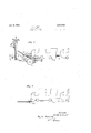
2 SHEETS-SHEET I Ry 2 26 2f -v L "1 /4 ...u/7 fl; 22 l J I .fl a /g vf 23/ f 65 /7/72 66 Jau 67 l /l/\ o 0 w e 42 2 s... i6'1. G 453/A 32 wao- 4 ff" I i f6 o lll] t i l: l Il 7 new se 3'/ w42 43 /z W U64 es v3 V-4q Jan. 2, 1923. Y' 1,440,585
C, G. FEUCHT ROLLER CoAsTER. FILED MAY l5. 1922. 2 SHEETS-SHEET? ilorizontal side rails 25 are pivoted at one oil? their endsupon the bar and the opposite l ends thereof` pass into forwardly extended openings 26l in the side walls or the car.- T he ends ot the bar 22 are supported in recesses in the side Walls in a similarnianner to that ot the bar 14, and the side bars 25 are locked in a corresponding manner byv the latch-bars 27. fit their upper ends the several latchbars are slidably mounted in the guide blocks 28, secured to the side walls ol' the car in a `iii-inner to; resist the thrust from the side rails in any attempt to open the gates, and at their lower ends the latch-bars are pivotally connected toV one end of the radius bars 29, the opposite ends of the latter being'pivotally inountedon the pins 30 linedto the side wallsofthe car., AAlso y l to the lowerends oft the latch-bars, are the toggle-links 3l which in turn are pivoted by the pins 3H to corresponding toggle links 33, the latter being pivotally secured at the lower end to the side walls oly the car by means of the pins 34?. At their pivotal points 32 the opposite toggle links are connected together by the connection bars 35 which in turn are pivotally connected by tl ine links 36 tothe lever arms 3'?, inedly secured upon the shalt 38, the latter eoztending` transversely across the car androtatively supported in the lflanged bearingsll secured to the opposite side walls thereof'. Ait one end the shalt projects exterior-ly' of the ear and is provided with a foot 'treadle 4:() in fixed relation with the shaft, which latten` midway its lenoth is also furnished with an oi eratine' lever el', having its free end pivotally eenn nectedto an actuating rod 4:2, the lower or trecend oit which extends below the floor oil? `the car.. Also 'surrounding the rod ,within the car is alielical spi'ng 43, the opposite ends ot' which exert a. thrusty betuf'een the floor olf the car and a collar fli4l adjust-ably .lined lengthwise of the rod, the said thrust of ythe springl normally 'tending to partially n urge the latch-bars 21 and 27j into locking position.
By ineansv of the 'toot treadle all kthe shalt 38, may, be rocked in opposite directions and 'which in turn acts through the arms o? and 'linlrs 36 reciprocate ,the coiniection bars 35,v the latter in their movements operi theliogglelinlrs 3l and `to jointly raise and lower the latehfbars and thus arranged it will be obvious that in eithei` one ol? thegates be not ftully closed the position ci the side bars i8 or thereof will interc'epl: thel upward orloclring inclement olf4 the jointly-connected latchbars21 and 27 and prevent the locking action oit either gate. lt will bel clear .that in like manner the device may also be applied to the gates oi: three or more? seats andthe locking action of any "one ofsaid gates will be dependent Ion the proper,reasoning@ all hreoff 'otally connected macteo lllhile the locking action oft suitably posi-7,
tioned gates may be readily effected by the foot treadle Lil), in the event ol' a. t'ailure on the part ol? the attendant this action may bek accomplished by the automatic upward moveinentvoli vthe actuating rod 42, the uppermostposition thereoi1 being shown in full lines while its lowerinost position is indicated by the dotted lines representing the lower-'or y projecting end of the rod, which in such position is adapted during the initial 'forward rod' lf2 causes the latter to be raised and efits advancement with its gates in locked ponk sition, it engages the upwardly inclined section 'lila et the track and also 'engages the chain il@ by means oit the dog 4-9, pivotally secured to the cai-.under the floor thereofL 'llhe driving chain l-S together with operating means may be et any appro'e'ed construction, the lower portion `1D0 only oit the chain being herein diagrammatically i .Y as carried by the sprocket wheel 50 and drwen through the belt 5l by the electric-motor 52, the current to the latter beinelv controlled by the switch handle operating in the usual niianner to open and close the electrical circuit. Y
ln the relativo position ol the several imi-ts as shown by full lines the cars with their gates in regularly loclted position are tree to be operated around the track inthe usual manner; and inthe event oli' an irregular p0- sitioned or unlocked gate in ofthe cars, thejactuating rod 42 thereot'u'ill be reta ined in'its lowerniost or projecting' rposition,` and in the lforward movement olf the car i l cause the cani section 415' to swin wardly about its pivotal point and,Coniprewy the connected spring Ll?, isthc increment ofthe car continues the proieetig will enfi 01e lie lippe;` arm el the lever pivotally upported by the lirainiet tlgie opposite arm .56 ot the lever being connected to a flexible cablel 57 leadingr in arouvenienli rod 1 0 manner to an arm 5S' of ai bell-rranltlever 125 vided with a-tension Springi connected to 130 the arm 5S and adapted to exert an upwardly pulling force thereon to normally hold the saine against a stop '63, and the sev- `the engagement of the projectingrod 42 with the arm 54, and inwhich movement lthe latter acts throueh the on* osite lower arm', cable 5'?, arms '58 and 60 and against the spring),- 62 to throwv the switch-handle 63 into the dotted position shown, thus opening the power circuit, stopping kthe drivingchain 48 and preif'enting further advancement of the carsalong the upwardly inclined traclr section. During the terminal gravity momentum of the train, the `projecting rod- 42 engages and'rides along the ripper surface of the extension bar 542, holding the arm 54 in its power cut o position, the length of the bar being` sufficient to insure engagement by the projecting rod 42 until the cars have come to a full stop. The interruption `of the driving mechanism will thus be maintained until the misplaced gate is properly adjusted and the projecting rod 42 disengagged from the extension bar 54, whereupon the switch operating' device will assume Aits normal inactive position by the reaction of the tension spring 82. ln the normal inoperative position of the switch operating` arm 60, the springl connections 6l thereof permit the independent manual operation of the switch-handle 53, but when the 'arm 60 automatically shifted to its cut-oli' position, as indicated by the dotted lines, the switch handle cannot again be operatedto turn the power or until thev gates are properly locked, and the projecting rod 42 is returned toits normally retracted Vand inoperairer position.
Referring` again to Figs. l and 2, the joint .automatic releasing` action of the latch bars 2l and 27 is eii'ectedthrough the means of Athe rack-bar 64, slldably mounted on the baci plate 65, fixed to the sidewall ofthe car. A. pair of flanged rollers 66 are rotaN tably supported on the baclr plate by the studs 67; the smaller diameter of the rollers passing through elongated perforations SS of thev rack-bar nf'hile the large.' danieter serves as a lateral support to hold the bar in slidable contact with the plate. As thus supported the raclrebar is' free to receive a vertical movement and to transmit such movement to the gear segment 69, ,fixed upon the shaft 38. ln the treadle operation of the latch bars 2l and 27, idle vertical movementsv of the raokfbar 34 are efetel from -platform having` a suitably arranged free asc 3 the segment gear 69, and for the active 0peration of the rack-bar the lower end thereof extends through andy projects below thc floor of the car and presents a contact vend adapted to engage an angularly positioned shoe '70, pivotally'supported at its lower end bv the bracket 70, fixed to the track support adjacentA the discharging station thereof, clearly shown in Fig.4. At its upper endv the shoe is provided with a compression spring` 7l adapted to exert an upwardprec'-` y sure thereon, and in lits engagement by the rack-bar during); the relatively slow termln-al movement of the car, the pressure ofthe spring 7l is suiiicient to overcome the operative.resistancel of the rack-bar and cause the latter to rotate the shaft 88 and jointlyv ef` feet the unlocking movement of the latch bars 21 and 27. To avoid possible accidents during the' running action of thes everal cars, the gatev locks and operating` means therefor are po. sitioned beyond the reach of theseated pasv sengers, the operative parts being partially enclosed below a seat of thecar and in part by separate casinpgs indicated at 72. It is to be understood that the traclrsection oom prising the receiving and discharging sta` tion for the passengers is provided With a space to'perinit the attendant to operatethc foot-treadle for loclnngrthe gates, and after the car has left the station to prevent further 'treadle operation by a protecting' cover therefor. es a further security at the loadstation it is to be noted that the side rails of the gates are conveniently supported and arranged to close the entrances to the -car when the seatsv are filled and prevent overcrowding` thereof.
It is to be understood that while I have illustrated and. described the preferred embodiment of the invention it is susceptible of various changes as regards its forni, proportion, detail construction, application and arrangement of parts, without departing from the essential principle and scope or sacricine' any of the advantagesthereof.
llVhat l claim as my invention and desire to secure by Letters Patent, is:
l. ln a rar of the clafs descril a f1 *te therefor har d. a seat,` l I loclnngr means, means for operating loclri l means beyond the reach of .ne j iassengen in said seat. and inea! for rende-rino; said locking means inrmrratrre when said 'gate' is unpertectly closed.
2. lu :x of the class described. a phrrallty of se ats, a rate for each of said seats provided with locking' .mez/ins.y means for joint-ly locking` said ira-tes beyond the reach of the passengers in said seat, and means for rendering said loclringineans inoperative when any of said gates are imperfectly' closed.-
l8. ln a car of the class described, a seat, agate therefor, locking means for said gate Aheld inoperativel when the gate is iinperfectly closed, means for locking said gate beyond the reach of the passengers in said seat, and means for releasing said locking means by the movement of the car.
il. In a car of the class described, a plurality of seats, a gate for each of said seats,
,locking means held inoperative When any of said gates are imperfectly closed, means 4for jointly locking said Agates beyond the reachof the passengers in said seats, and
ymeans for joint-ly releasing said locking `mean by the movement or the car.
5. In a car of the class described, a. seat,
a gate therefor', having side rails disposed tov elosethe entrance to said seat, passages formed in the side Walls Aof said car and arranged to laterally support said side rails and to receive the same in the closing move-y lment of said gate.
6. ln a ear of the class described, a seat,
a gate therefor having side rails disposed the failure of the foot-treadle action.
8. 1n a car of the class described, a plurality of seats, a gate for each of said seats, means including a foot-treadle lnormally serving to jointly lock said gates in closed position, and automaticI means operated by the movement of the car to effect the joint locking movements of said gates upon the 'failure of the foot-treadle action.
9. In a car of the class described, a seat, a gate therefor, treadle operating` means normally serving to locli said gate in closed position, and automatically operated means for locking said gate upon the failure of said trea-dle operating means.
10. In a car of the class described, a seat, gate therefor, means including a foottreadle normally serving to loclr said gate in' closed position, means actuated by said foot-treadle for releasing said ioclring means, and means actuated by the movement of the car for releasing said locking means independently of said foottreadle.
11. in a car of the class described, a plurality of seats, a gatel for each of said seats,
means including a foot-treadle for jointly locking said gates in closed position, means actuated by said foot-treadle'for'jointly re'- leasing said locking means, and. means acinadeee tuated by the movement of the car Ifor releasing said locking means independently of said foot-treadle.
12. lin a car of theclass described, `a gate,
means operated by a foot-treadle for lock-v 14;. ln a car gate, locking means therefor including a rock shaft, a foot-treadle connected to said shaft for lockingsaid gate, means independent ofv said foot-treadle for rocking said shaft by the movement ofthe car to lock said gate, a source of power arranged to elevate said car, and means actuated by the movement of the car to cut off said sourcel of power upon the failure of said independent lockingmeans.y
1,5.- ln acar gate, locking means therefor arranged to be operated by a foot-treadle, and locking means for said gate arranged to be operated by the movement of the car upon the failure of said foot-treadle lockingmeans.
16. 1n car provided. With elevating means arranged to be engaged by the manual initial movement of said car, a gatev for said car adapted to be manually closed, locking means for said gate arranged to be operated by a foot-treadle, locking means for said gate arranged to be operated by the initial movement of said car upon the failure of said foot-treadle locking means, and means operated by the initial movementv of the car to arrest the elevating ymovement thereof upon the failure of the said several gate locking means.
17. A; gate for a car seat, comprising a handle-bar arranged to be operated into open l andclosed position with respect to said seat, uprights secured to said handle-bar andarranged to mo'vably'support the latter inits open and closed positions, and side bars connected to` saidy gate sections andY adapted to close the car entrancesto saidseat..
18. A car gate 1 comprising a pair of upright; members having a horizontal member or handle-'bar connected thereto and mounted for swinging movement, a pair ofv side rails included in said'gate members andy ar,- ranged to move across and'close the entrance of said car, and locking means for said gate consisting of a pair, ofjlatch bars arranged to move, across. the pathV offsaid side rails.
19; A. car, gate includinga pairofv side rails arranged to move across and close the entrance of said car, latch-bars arranged to move across the path of said side rails and lock the gate in a cldsed position, 'means for operating said latch-bars consistin g of toggle links having connection rods leac ing to a rock shaft, and a foot-treadle fixed to and adapted to actuate said rock shaft for the locking and releasing movements of said latch-bars.
20. A car gate including a pair of side rails arranged to move across and close the entrance ot said car, latch-bars arranged .to move across the path of said side rails and lock the gate in a closed position, means for operating said latch-bars consisting of toggle links having connection rods leading to a. rock shaft, a oot-treadle fixed to and adapted to actuate said rock shaft for the locking and releasing movements of said latch-bars, and means independent of said oot-treadle for rocking said shaft for the release of said latch-bars consisting of a segmental gear iiXed to said rock-shaft, and a rack-bar engaging lsaid segmental gear.
2l. in a car of the class described, power advancing means therefor, a gate for said car, locking means for said gate normally operated by an attendant, yielding means adapted to be operated by the advancement of the car for locking said gate upon the failure of operation by the attendant, and means operated by the movement of the carto arrest said power advancing means upon the failure of operation of said yielding means. c
22. In a car gate, locking means therefor inciuding an actuating rod projecting from said car and adapted to be operated by the movement thereof, the said rod remaining inoperative with respect to said locking means when the gate is imperfectly' closed, a source of power arranged to elevate said car, lever arm disposed for engagement bysaid actuating rod during the movement of the car, and connecting means between the lever arm and said sourceof power whereby the latter will be cut oit and the elevating movement of Jglie car arrested when the gate i is unlocked. i i
23. ln a car gate, locking means therefor including an actuating rod projecting from said car and adapted to be operated by the movement thereof, and a cam' section dis,-
' posed to be engaged by said actuating rod duringthe movement of the car and operate said locking means.
'24. in a car gate, locking means therefor -movement of the car, and connection `means between the lever arm and said source of power whereby the latter will be cut off and theelevating movement of the car arrested when the gate is unlocked.
Q5. in a car of the class described, a gate,
locking `means vfor said gate, a source of power arranged to elevate the car, and means for automatically cutting oii' said power upon the failure oiE the gate locking means. Qd in a car oit the class described, a gate, locking means for said gate, a source of power arranged to velevate the car, means for automatically cutting od said power upon the failure of4 the gate locking means, and meanswhereby the power will vremain inoperative whilethe gate is unlocked.
Signed at Brooklyn in the county` of Kings and State or' New York May A. D. 192e, y y
CHRISTIAN G. FEUUHT.
this 10th day of
Priority Applications (1)
| Application Number | Priority Date | Filing Date | Title |
|---|---|---|---|
| US561091A US1440586A (en) | 1922-05-15 | 1922-05-15 | Roller coaster |
Applications Claiming Priority (2)
| Application Number | Priority Date | Filing Date | Title |
|---|---|---|---|
| US561091A US1440586A (en) | 1922-05-15 | 1922-05-15 | Roller coaster |
| GB3306022A GB206388A (en) | 1922-12-04 | 1922-12-04 | Improvements in roller coasters and cars therefor |
Publications (1)
| Publication Number | Publication Date |
|---|---|
| US1440586A true US1440586A (en) | 1923-01-02 |
Family
ID=26261694
Family Applications (1)
| Application Number | Title | Priority Date | Filing Date |
|---|---|---|---|
| US561091A Expired - Lifetime US1440586A (en) | 1922-05-15 | 1922-05-15 | Roller coaster |
Country Status (1)
| Country | Link |
|---|---|
| US (1) | US1440586A (en) |
Cited By (2)
| Publication number | Priority date | Publication date | Assignee | Title |
|---|---|---|---|---|
| US2592879A (en) * | 1949-02-04 | 1952-04-15 | Lee U Eyerly | Safety device for amusement rides |
| US5454596A (en) * | 1993-04-15 | 1995-10-03 | Dirck; Ronald L. | Safety restraint apparatus |
-
1922
- 1922-05-15 US US561091A patent/US1440586A/en not_active Expired - Lifetime
Cited By (2)
| Publication number | Priority date | Publication date | Assignee | Title |
|---|---|---|---|---|
| US2592879A (en) * | 1949-02-04 | 1952-04-15 | Lee U Eyerly | Safety device for amusement rides |
| US5454596A (en) * | 1993-04-15 | 1995-10-03 | Dirck; Ronald L. | Safety restraint apparatus |
Similar Documents
| Publication | Publication Date | Title |
|---|---|---|
| US1440586A (en) | Roller coaster | |
| US1616368A (en) | Automatic feeder | |
| US653769A (en) | Car-step. | |
| US1539218A (en) | Gravel loader | |
| US1510600A (en) | Car-operated mine door | |
| US1398896A (en) | Mine-car-controlling mechanism | |
| US1613872A (en) | Automatic gate | |
| US536665A (en) | Car-fender | |
| US1374828A (en) | Railroad-crossing gate | |
| US1137699A (en) | Street-car fender. | |
| US1297197A (en) | Railroad-gate. | |
| US599847A (en) | Railway-switch and means for operating same | |
| US1584746A (en) | Automatic lock and release for mine cars | |
| US253673A (en) | Gripe for propelling cars | |
| US559891A (en) | gratheb | |
| US1092633A (en) | Automatic door opening and closing device for elevators. | |
| US1407329A (en) | End-gate raiser for mine cars | |
| US754844A (en) | Track-brake for cars. | |
| US773002A (en) | Car-platform-operating device. | |
| US155550A (en) | Improvement in turn-tables for railways and bridges | |
| US466165A (en) | Automatic railway-gate | |
| US1377901A (en) | Gate | |
| US1021686A (en) | Dumping-car. | |
| US891270A (en) | Car-fender. | |
| US1801973A (en) | Step and trap construction for passenger cars |