US1410179A - Demountable rim - Google Patents
Demountable rim Download PDFInfo
- Publication number
- US1410179A US1410179A US1410179DA US1410179A US 1410179 A US1410179 A US 1410179A US 1410179D A US1410179D A US 1410179DA US 1410179 A US1410179 A US 1410179A
- Authority
- US
- United States
- Prior art keywords
- rim
- wheel
- demountable
- plunger
- block
- Prior art date
- Legal status (The legal status is an assumption and is not a legal conclusion. Google has not performed a legal analysis and makes no representation as to the accuracy of the status listed.)
- Expired - Lifetime
Links
- 230000004048 modification Effects 0.000 description 4
- 238000006011 modification reaction Methods 0.000 description 4
- 241000985694 Polypodiopsida Species 0.000 description 2
- 235000003642 hunger Nutrition 0.000 description 2
- 230000000414 obstructive Effects 0.000 description 2
- 235000013533 rum Nutrition 0.000 description 2
- 239000004576 sand Substances 0.000 description 2
- 238000003466 welding Methods 0.000 description 2
Images
Classifications
-
- B—PERFORMING OPERATIONS; TRANSPORTING
- B60—VEHICLES IN GENERAL
- B60B—VEHICLE WHEELS; CASTORS; AXLES FOR WHEELS OR CASTORS; INCREASING WHEEL ADHESION
- B60B23/00—Attaching rim to wheel body
- B60B23/04—Attaching rim to wheel body by bayonet joint, screw-thread, or like attachments
-
- Y—GENERAL TAGGING OF NEW TECHNOLOGICAL DEVELOPMENTS; GENERAL TAGGING OF CROSS-SECTIONAL TECHNOLOGIES SPANNING OVER SEVERAL SECTIONS OF THE IPC; TECHNICAL SUBJECTS COVERED BY FORMER USPC CROSS-REFERENCE ART COLLECTIONS [XRACs] AND DIGESTS
- Y10—TECHNICAL SUBJECTS COVERED BY FORMER USPC
- Y10T—TECHNICAL SUBJECTS COVERED BY FORMER US CLASSIFICATION
- Y10T70/00—Locks
- Y10T70/50—Special application
- Y10T70/5889—For automotive vehicles
- Y10T70/5982—Accessories
- Y10T70/5987—Spare or mounted wheel or tire
- Y10T70/5991—Tire or rim only
Definitions
- Figure 2 is a section on line 2-2 of F ig- Figure 3 is an elevation ofthe preferred form of head. and 'cam for moving the the rum.
- a demountable rim attaching arrangement including, with a wheel, a rim, said rim having a block attached to the concave side thereof, which block is provided with a socket therein, a spring-pressed plunger carried in the wheel felloe and radially movable therethrough, the block having an inclined slot extending from the rear edge of the block to the socket, whereby said rim ma be guided in its'application to the wheel by engagement between the slot and the plun- 'er.
Description
P. HIEN.
DEMOUNTABLE RIM,
APPLICATION FILED JAN; 7, 1918.
17,410, 179. Patented Mar. 21, 1922.
II J3 UNITED STATES PATENT OFFICE? PHILLIP Bran/or esisie m si I DEMOUNTABLE RIM.
To all whom it may concern: 7 I I Be it known that I, PHILLIP HIEN, a citizen of the United States, residing at Chicago, in the county of Cook and. State of Illinois, have invented certain new and useful Improvements in Demountable Rims, of
which the following is a specification.
My invention relates to vehicle wheels and .ure 1;-and
particularly to demountable rims for motor vehicles.
One of the objects of my invention is to provide a simple and efficient means for relnovably securing demountable rims to wheels.
Another object is toiprovide a'meansfor removably securing demountable rims to vehicle wheels which is positive in operation and which does not unduly subject the rims to wedging strains. w
Afurther object is to provide a mean for removably securing demountable rims to vehicle wheels which when applied will prevvent lateral or circumferential movement of the rims relative to the wheels.
A still further object is to provide means Q placed or often times damaged to such an 40,
extent as to be unfit for further use My invention seeks to overcome the above recited objections by providing a plurality of plungers radially mounted in the felly of the wheel and normally maintained outwardly of the felly preferably. by spring pressure. The inner ends of thelplungers are provided with novel heads having. cam surfaces which when turned will retract the .plungers, all of the variousparts being self contained and having no part tov be removed when it is found desirable to change the rims so as toeliminate the possibility of lossof some of the parts and remove all likelihood of damage. 1 j
My inventionwill be more fully described nd pointed. out in thefollowing descrip- Specifiction ofidttfls e PatentedMarLZI, 1922. Application filedJanuary 7, 1918. 5 Serial No. 210,665.
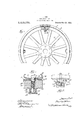
tion inconnection-with which reference is -tion, a portion of the wheel being cut away to: show the cooperative'elements..
Figure 2 is a section on line 2-2 of F ig- Figure 3 is an elevation ofthe preferred form of head. and 'cam for moving the the rum.
plungers out. of operative engagement with A i 5 designates amotor vehicle wheel having the usual spokes '6 and hub 7 a 8 is the usual felly and in the form shown is oblong or rectangular in section. *Mounted on the outer portion of; the felly .is a permanent rim 9having its inner edge'out-turned forming a flange l0 wh1chextendsaround the inner portion of the felly forming a shoulder 11 or I abutment forlimiting :the inward movement of the demountable rim 11 onthe wheel.
.In the form whichl have chosen to illusrims the permanent rim isinclined to afford easy application of the demountable rim. The demountable rim 11 is provided at in-.%
tervals with apertures 12 extending through the rim body. Secureda to. the under side of therim 11 area. series of spacers 13 which spacers are provided'with bosses 14 for extrate my invention the surfaceof the perma- 'nent rim 9-is parallel toT theaxial line of thewheel, In some forms of demountable tending into the apertures 12 of the rim,
and interfittingtherewith. The spacers 13 .are securely. fastened ,to the'rim by rivets,
welding, or inanyother suitable manner. The-under sides of the spacers '13 are counwill. hereinafter be more fully set out. The felly 8 andthe permanent rim Qareprovided with a series of-registering apertures 'terbored forming recesses 15 which I prefer** to extend-into theboss 11 for reasons which 16, 1-7. Mounted therein zare the plungers- 18 which in the preferred form of my invention comprisea reducedmemb'er orstem 19,
andhead 20; in shape and size substantially thatof the counterbore :15 infthe spacers 13. Surrounding the stem 19 is a coil spring 21 normally acting to move the head 20 outwardly-The :plungers are maintained in. operativeposition in thekfell-yby being mounted ,in; a" casing-22} which. is secured .to
the f l yin any We l kn wn manner such as by screws 23. The casmiis prolidfld.
cams. The ends of theeanasnriqwes are pvoh vided with flattened portions 2Q", 28?,
29, for the purpose eimtaining'the plungers in withdrawn position, when the flattened portions of the cams are brought into As is usual, demountable rims are moved laterallty ontoand ofi ofthe vehicle wheel. To
ease of removal and application it is permit v I necessarythat suifi'cient play provided fier'between the permanentrnn and the demount'ablerim. I have provided} ior this by using-spaeers 13 sothat it is unneeesssryto'make the perm'anent'rim 9 inelined as is usually done The inner portions of the spacers 13 are provided: with inclinedfaces 1 seas to iorce theplun 18 inwardly as the rim is being: applie if theplungers should be in an outward position. I
One of the objections to the useof demountable rims has been the lateral as well as circumferential movement "01 the rim with respect to the wheel. As a result of such rim 11' and movement squeaking often occurs whenever sand or the like entersbetween the rim and the folly, also relative movement is likely to bend or shear the valve stem which passes through the fell'y and is connected with the inner tube oithe tire on the rim.- Furthermoreflf any play is permitted between the rim and the wheel then the various parts eonneoting the rim and the wheel are subjected to undue strain when the vehicle is in motiomfall of which tends to be detrimenta'al ra-ther-thanbenefioial. To overcome lateral and circumferential movement of the wheel] have provided the spacers 13 with bosses 14 extending-15h the ferns the 1 with a sufieient depth topem'ait head of hunger to enter me the, inner sur- --faeeo1 'the i'im, I transier the driving strains direet to them and me osis rim three the medium of wedges or spacers If the plunger head 20 extended through the rs 13-only and beyond the inner sol-flees of the mm- 11 iiieigfindency would eventually be to shear dea,pvereome has yeetaonan' aveprevi a ifive ebnnee' tron" rm the rim should not beoentered properly.
Wheel. Furthermore, the fit between the head 2(land the counterbore 15 is such as at all times to hold the rim 11 against the shegisler or flange 10, thus preventing the lateral movement of the rim 11. The same fit vents circumferential movement of the rim on the wheel. By making the head 20; oi sufliciont' sizato engage tightly the upper portion of the aperture 16 in the felly 8 and pass through the aperture 17, in the rmanenb rim 9: and through the counterre 15 0;! the spacers 13 there is no tendency whatsoever to permit any sort of play as v regards the head of the plunger and consequently, the rim on the wheel. If desired, the upper of the head 20 may be chamfered as at 20 which will tend to seat the 11 securelyin position on the wheel as the head 20 is forced in the counterbores 15 by-the action of the spring 21 if'the rim l The operation of the device is as follows: The rim being applied to the wheel as shown in Figures 1 and'2, it is desired to i'emove the rim i rom the wheel. To accomplish this heads-'27 are turned either-by hand or by toolif iound necessary which turning will, by virtue of the cams 25. 26,
'28 and. 29 cause the heads 2'7 to ride on the cams 25,126 therebycaus'ing theplungers 18 to move inwardly with respect to the felly and withdraw the heads 20 from engagement with the counter-bores 15 in the rim and spacers. When allof the plunger-s 18 have been withdrawn'and held in withdrawn p0- si tion by" turning thefl'attene'd portions 25, 26, 28", 29*, into engagement the rim 11 may be removed in the usual 'manner. It will be observed thatthere is no obstruction of any sort to the removal of the rim when the plungers are withdrawn as above described. To replace the same or another run on thewheel, the plungers being inretracted position the rim is applied. the usual valve stem being inserted in the aperture (not shown) in the fel-ly provided for that pure. The rim is then moved against the P shoulder 10. The heads 27 on the plunger 18 are then turned only'so far as to disenge the flatten d faces 25, 26', 28, 29; and
t sprin s 21i will' cause the plungersto be 'moved in o engagement with the? counterbores 15 on-the infierportion of the'rim. It will'be observedth'at the plhngers as seat-the Tim 'on the wheel is practicaliy automatic. due to the-action of the springs 21 whenthe heads '27 are're- I leased withholding position. 1 The ten- 211m, be varied tomeet sion of the spin the various eon itions'o service. It'isj'of fr the M iirsenunderstood that heavier rims will '8 :the gamers with the reqhir'e heavier springs and lighter rims -l ter springs. It will be observed that m te-"the mid position wheel movement of the through the spacers 13 and directly through the axial line of the spokes, in the case of a Wooden Wheel. The abutment between the rim l1 and the shoulder 10 tends to steady the rim on the wheel, also limits the inward position of the rim. It is, of course, understood that rim 11 carries the usual tire, the form shown being that adapted for a clincher tire. It is understood that a de mountable rim may be adapted to take any kind of a tire, clincher, Q. D., straight side or any other standard make as the shape of the rim and kind of tire used thereon does not form a part of my invention.
It is obvious that modifications of such a. device may be made and the modifications of which such a device are susceptible I consider as coming within the scope of my invention as embodied in the appended claims.
I claim:
1. A demountable tire rim fastening device, including in combination with a wheel, a rim, a shouldered block interfitting with an opening in the rim and having a socket therein extending beyond the inner or concave surface of the rim, a spring-actuatecl plunger mounted in the wheel felloe for radial movement therein and having a head adapted to enter the socket in said block, the other end of the plunger carrying a cam for engaging a cam surface on the felloe, said cams having flattened portions whereby to retain said plunger out of engagement with the rim under certain conditions.
2. A demountable rim attaching arrangement, including, in combination with a wheel, a rim having a block attached to the concave side thereof, said block having a socket therein, a spring-pressed plunger carried in the wheel felloe and radially movable therethrough for engaging said socket'under certain conditions, the block having an inclined slot extending from the inner edge of the block to the socketwhereby said plunger may be moved inwardlyof the wheel to per mit application thereto of the rim.
3. In combination with a vehicle wheel, a
tire rim removably surrounding the wheel felloe, a plurality of spaced blocks having sockets formed therein and secured to the tire rim projecting inwardly of the inner surface thereof, each of said blocks having an inclined counter bore ortion forming a socket therein extending rom the inner end of the block to the inner surface of the tire rim, radially movable plungers mounted in the wheel felloe and spaced to align with the sockets in said blocks, and means for radially moving said plungers into and out of engagement with the sockets in the respective blocks, said plungers being guided by the cut-away portions of the blocks into alignment with said sockets.
4:. A demountable tire rim fastening device, including, in combination with a wheel, a shouldered block interfitting with an opening in the rim, said block having a socket therein extending beyond the inner or concave surface of the rim, a spring-actuated plunger mounted in the wheel felloe for radial movement and having a head adapted to enter the socket in said block, the other end of the plunger carrying a cam for engaging another cam on the felloe, said cams having flattened portions whereby to retain said plunger inwardly of the felloe band clear of the rim when said flattened surfaces of the cams are in contact.
5. A demountable rim attaching arrangement, including, with a wheel, a rim, said rim having a block attached to the concave side thereof, which block is provided with a socket therein, a spring-pressed plunger carried in the wheel felloe and radially movable therethrough, the block having an inclined slot extending from the rear edge of the block to the socket, whereby said rim ma be guided in its'application to the wheel by engagement between the slot and the plun- 'er.
b Signed at Chicago, State of Illinois, this 21st day of December, A. D., 1917.
PHILLIP I-IIEN.
Publications (1)
| Publication Number | Publication Date |
|---|---|
| US1410179A true US1410179A (en) | 1922-03-21 |
Family
ID=3401009
Family Applications (1)
| Application Number | Title | Priority Date | Filing Date |
|---|---|---|---|
| US1410179D Expired - Lifetime US1410179A (en) | Demountable rim |
Country Status (1)
| Country | Link |
|---|---|
| US (1) | US1410179A (en) |
-
0
- US US1410179D patent/US1410179A/en not_active Expired - Lifetime
Similar Documents
| Publication | Publication Date | Title |
|---|---|---|
| US2198978A (en) | Rim construction | |
| US1410179A (en) | Demountable rim | |
| US2323502A (en) | Motor vehicle wheel | |
| US2003109A (en) | Wheel structure | |
| US2229724A (en) | Wheel | |
| US1664765A (en) | Wheel structure | |
| US2283860A (en) | Wheel structure | |
| US2197608A (en) | Wheel | |
| US1376205A (en) | Disk vehicle-wheel | |
| US2210451A (en) | Vehicle wheel | |
| US1583222A (en) | Wheel for industrial trucks | |
| US1460413A (en) | Spring wheel | |
| US1994375A (en) | Vehicle wheel | |
| US1483654A (en) | Vehicle wheel | |
| US1595182A (en) | Wheel and tire | |
| US1923811A (en) | Wheel for motor vehicles | |
| US1817700A (en) | Means locking pneumatic tires on wheels | |
| US1923476A (en) | Method of forming suspension wire wheels | |
| US2586206A (en) | Truck rim design | |
| US1708439A (en) | Machine for assembling spoked-wheels | |
| US1324293A (en) | Eele king baker | |
| US1325258A (en) | Wheel | |
| US1877379A (en) | Vehicle wheel | |
| US1375435A (en) | Demountable rim | |
| US1426582A (en) | Resilient vehicle wheel |