US1410175A - Oil-cracking apparatus - Google Patents
Oil-cracking apparatus Download PDFInfo
- Publication number
- US1410175A US1410175A US359378A US35937820A US1410175A US 1410175 A US1410175 A US 1410175A US 359378 A US359378 A US 359378A US 35937820 A US35937820 A US 35937820A US 1410175 A US1410175 A US 1410175A
- Authority
- US
- United States
- Prior art keywords
- valve
- still
- pressure
- oil
- vapor
- Prior art date
- Legal status (The legal status is an assumption and is not a legal conclusion. Google has not performed a legal analysis and makes no representation as to the accuracy of the status listed.)
- Expired - Lifetime
Links
Images


Classifications
-
- C—CHEMISTRY; METALLURGY
- C10—PETROLEUM, GAS OR COKE INDUSTRIES; TECHNICAL GASES CONTAINING CARBON MONOXIDE; FUELS; LUBRICANTS; PEAT
- C10G—CRACKING HYDROCARBON OILS; PRODUCTION OF LIQUID HYDROCARBON MIXTURES, e.g. BY DESTRUCTIVE HYDROGENATION, OLIGOMERISATION, POLYMERISATION; RECOVERY OF HYDROCARBON OILS FROM OIL-SHALE, OIL-SAND, OR GASES; REFINING MIXTURES MAINLY CONSISTING OF HYDROCARBONS; REFORMING OF NAPHTHA; MINERAL WAXES
- C10G9/00—Thermal non-catalytic cracking, in the absence of hydrogen, of hydrocarbon oils
- C10G9/06—Thermal non-catalytic cracking, in the absence of hydrogen, of hydrocarbon oils by pressure distillation
- C10G9/08—Apparatus therefor
Definitions
- the present invention embodies the matters claimed in my said-patent and provides certhe upwarc tain improvements in the vapor shut-off means which will become apparent from the specification.
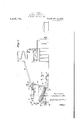
- ig. l is an elevation of a still and adja- Fig. 2. is an enlarged vertical cross-section on the line 22 of Fig. 1.
- Fig. 3 is a semi-diagrammatic view, partly in section, showing conventionally, the means'for maintaining pressure in the eduction stem.
- A represents a petroleumstill of the tubular type having a vapor outlet at the top and toward the rear .of its shell a, with which is connected the'vapor' eduction and condensing system, as illustrated in my said prior patent and here representedgby ly inclined vapor pipe B, said pipe having a vertical neck D secured in the outlet.
- the inclinedvapor pipe as is well known, is for the purpose of condensing and returning to the still all products heavier distant point in the system, beyond the condenser, 1s a valve or valves, not shown, whereby the desired pressure is maintained in the still and system.
- the expansion strains are severe, and even with swing joints there 1s always the possibility of some part from the neck D onward giving way, in which event there is forcible escape of highly inflammable vapors and oil above the flash
- the vapor neck D extends downwardly into the vapor space of the shell fora distance below the top, and is provided at its lower end with a beveled annular valve seat 11, which is preferably formed on a ring 11*" which is suitably secured to the exterior ofthe lower end of the neck.
- Guides 25 proj ect downward from this ring around a valve disk 10, the periphery of which is upwardly beveled at 10 to co-operate with the seat 11.
- a valve rod 12 is secured to the disk 10 and extends upward therefrom in the neck D.
- the said rod preferably passes completely through the said neck and through a cross-header D at the top thereof, to which the dephlegmator pipes B are connected, the rod extending through an opening in the top wall of this cross-header and through a'stufiing-box 19 mounted thereon.
- a fulcrum bracket 30 is clamped at 31 about athimble 32 at the base of the stufling-box, and its upwardly-projecting arm affords pivotal support at 33 to a two-armed lever 34 disposed over the vapor neck and crossheader. The short arm of this lever is connected by a ivotal link 35 with the upper end of the va ve rod 12.
- a spring device 37 preferably in the nature ofa comparatively light or weak wire containing a certain amount of resilience or elasticity, as indicated at 38, also opposes p01 through the neck.
- this device is a destructible tying connection interposed between the weight 36 and. an anchoring pin 39 on the stuffing-box, serving, thus to restrain the valve and valve mechanism from chattering or vibrating in the normal operation of the still. It also contributes toward preventing undesired closing of the valve through fluctuations in the pressure or flow, and in some instances it may be the sole instrumentality for holding the valve normally open.
- the vapor shut-oil valve 10 is normally open and will remain so in spite of the occurrence of a substantial difference in. pressure between system sufficient to create an outrush ot-va- This is becauseof the substantial distance of the valve from its seat in the open position and of the biasing effect of the weight 36 and the weight of the valve and valve rod itself, with or without the restraint of the tying means 37.
- Closing of the valve in case of necessity, that is to say when a break develops in the eduction and condensing system, is caused by the attendant pulling upon the handle 41 of thecable 21, which breaks the wire 37 and raises the weight 36 and the valve 10 sufficiently to enable the pressure and velocity conditions to exercise control, whereupon the valve is immediately driven to itsseat and held there by virtue ofithe difference in pressures until suchtime as the excess oft pressure within the still has, been largely removed by the pumping-out means, presently to be described.
- the weight of the parts automatically reopens the valve, thereby avoiding the necessity of this being done through action of the attendant and avoidingthe possibility n Lemme of the valve remaining closed through oversight after the difiicult-y in the eduction systern has been corrected and thestill again placed in commission.
- the mounting still pressure may blow off to a safety valve S, wherein theoutflow is so controlled as to avoid the danger of fire.
- the ioregoing vapor valve mechanism may be used either with a simple shell still, such as shown in my prior patent, or in a tubular still wherein a bulk supply otoil is contained in a shell connected with a nest of cracking and vaporizing tubes exposed to the fire.
- Oth'eraspects of the present invention relate to a safety system for this particular type still. As illustrated in thedrawings theshellc is supported in a suitable elevated position, whereit is exposed to the'outside atmosphere and cut off from the direct heat ot the fire.
- the inclined cracking and vaporizing tubes 1 extend between'tront and rear headers 0 and d, which are connected with bottom topen ings in the shell by front and rear downcomers e and Ina still of this character the oil circulates downward through the rear downcomer f to the rear header d, upward and forward through the mu1tip'l'icity of tubes Z), where the vapors are generated which become cracked or thermolized under the conditions existing in the still, the vapors passing upward throu h the for-- ward downcomer 6 into theshelli' where they become disengaged from the liquid andoc cupy the upper part of the shell interior.
- Pumping-out means comprising two branches co nnecte'd, respectively, with the shell and with the tubular part of the still,'tha t is to Say the parts of the still which may be cut off from-each other by the closing of the valves 4A.
- One pumping out line .56 passes from the bottom of the rihead'er d to a cooler coil 5.7, and therice aili emptying pump 58'.
- the other p pi line 59 has its inlet end within the shell, near the bottom, whence it extends upward through the top of the still andeventually to a cooler coil 60, and thence to an gisnptying pump 61.
- a pressure oil still comprising a shell having a vapor outlet at the top, a vapor eduction system connected with said outlet, and means for maintaining a substantial'pressure in the eduction system and still; a valve in the upper part of the shell movable upward to a seat at theentrance to the eduction system and adapted to be held thereto by the pressure in the shell after rupture in the eduction system, means biasing said valve 'to the open position, and attendant-operated means for overcoming said biasing means and starting the valve on its closing movement.
- apparatus for pressure cracking of petroleum or its higher boiling point fractions including a pressure oil still comprising .a shell having a vapor outlet at the top, a vapor eduction system connected with said outlet, and means for maintaining a substantial pressure in the eduction system and still; a valve in the upper part of the shell movable upward to a seat at the entrance to the eduction system and adapted to be held thereto by the pressure in the shell after rupture in the eduction system, means biasing the valve to the open position, means tying the valve in this position, and attendant-operated means connected with the valve for breaking the tying means and starting the valve on its closing movement.
- valve mechanism connected with the valve and shell. movable upward to a seat at the entrance to the eduction system and adapted to be held thereto by the pressure in the shell after rupture 1n the eduction system,
- a pressure oil still comprising a shell having .a vapor outlet at the top, a vapor eduction system connected with said outlet, and means for maintaining a substantial pressure in the eduction system and still;
- valve in the upper part of the shell movable upward to a seat at the entrance to the eduction system and adapted to be held thereto by the pressure in the shell afte' rupture in the eduction system, a weight bi sing said valve to the open position, and attendantoperated means for overcoming said biasing 100 means and starting the valve on its closing movement.
Description
J. B. EDWARDS.
OIL CRACKING APPARATUS.
APPLICATION FILED FEB 17, 1920.
1,410, 175. Patent-w Mar. 21, 1922.
, 3 SHtEIS -SHEET CO L?) '6; Arromvsr J. B. EDWARDS.
OIL CRACKING APPARATUS. ,APPLICATION FILED FELL, 1020.
1,410,175. Patented Mar. 21, 1922.
3 SHLETS-SHEET Z.
MIME/wok ATTORNEY J. B. EDWARDS.
OIL CRACKING APPARATUS.
APPLICATION m u FEB. 17. 1920.
1,410,175, Patented Mar. 21,1922.
3 SHtETSSHEET '3.
lEaQIZZfor: I J. 13. Eclauarcla,
' break such as not infrequently occurs at one I UNITEDISTATES PATENT OFFICE.
. I'OSEPH .B. EDWARDS, or JERSEY CITY, NEW JERSEY, ASSIGNOR r0 TIDE war COMPANY, or BAYONNE, NEW JERSEY, A CORPORATION or NEW JERSEY.
OIL-CRACKING APPARATUS.
-Speeificat1on of Letters Patent. Patented lu 21 1922 Original application filed August 8, 1918, Serial No. 248,846. Divided and this application'flled February 17, 1920. Serial No. 359,378. r
' To all whom it may concern:
Be it known that I, JOSEPH B. EDWARDS, a citizen of the United States, and resident of Jersey City, in the county of Hudson and State of New Jersey,'have invented'a new and'useful Oil-Cracking Apparatus, of which the followingis a'specification.
In my Patent No. 1,277,884, dated September 8, 1918, I have disclosed safety means for petroleum cracking apparatus of the kind wherein a still containlng a bulk of oil, and an extensive vapor eduction and condensing system leading therefrom, are both maintained undera substantial backpressure of the vapors, and wherein, consequently, a
point or another in the eduction system will ordinarily cause the heated contents of the still tobe expelled into the atmosphere, wherethey ignite. A fire started in thls way is uncontrollable, because of. the large amount of oil involved and the pressure which drives it forth, and is the more serious because a number, of the stills are usually built in a row or-battery, the whole of which is likely to be destroyed, as has occurred. The present invention embodies the matters claimed in my said-patent and provides certhe upwarc tain improvements in the vapor shut-off means which will become apparent from the specification.
In the accompanying drawings forming a art hereof: j
ig. lis an elevation of a still and adja- Fig. 2. is an enlarged vertical cross-section on the line 22 of Fig. 1.
, Fig. 3 is a semi-diagrammatic view, partly in section, showing conventionally, the means'for maintaining pressure in the eduction stem.
In igLI, A represents a petroleumstill of the tubular type having a vapor outlet at the top and toward the rear .of its shell a, with which is connected the'vapor' eduction and condensing system, as illustrated in my said prior patent and here representedgby ly inclined vapor pipe B, said pipe having a vertical neck D secured in the outlet. The inclinedvapor pipe, as is well known, is for the purpose of condensing and returning to the still all products heavier distant point in the system, beyond the condenser, 1s a valve or valves, not shown, whereby the desired pressure is maintained in the still and system. In the vapor part of the eduction system the expansion strains are severe, and even with swing joints there 1s always the possibility of some part from the neck D onward giving way, in which event there is forcible escape of highly inflammable vapors and oil above the flash the vapor neck D extends downwardly into the vapor space of the shell fora distance below the top, and is provided at its lower end with a beveled annular valve seat 11, which is preferably formed on a ring 11*" which is suitably secured to the exterior ofthe lower end of the neck. Guides 25 proj ect downward from this ring around a valve disk 10, the periphery of which is upwardly beveled at 10 to co-operate with the seat 11. A valve rod 12 is secured to the disk 10 and extends upward therefrom in the neck D. In the present instance the said rod preferably passes completely through the said neck and through a cross-header D at the top thereof, to which the dephlegmator pipes B are connected, the rod extending through an opening in the top wall of this cross-header and through a'stufiing-box 19 mounted thereon. A fulcrum bracket 30 is clamped at 31 about athimble 32 at the base of the stufling-box, and its upwardly-projecting arm affords pivotal support at 33 to a two-armed lever 34 disposed over the vapor neck and crossheader. The short arm of this lever is connected by a ivotal link 35 with the upper end of the va ve rod 12. Upon the same arm is hung a weight 36 of sufficient magnitude to bias the valve 10 to the normally open position illustrated in Fig. 2. I A spring device 37, preferably in the nature ofa comparatively light or weak wire containing a certain amount of resilience or elasticity, as indicated at 38, also opposes p01 through the neck.
some resistance to the closing movement of the valve. in the illustrated construction this device is a destructible tying connection interposed between the weight 36 and. an anchoring pin 39 on the stuffing-box, serving, thus to restrain the valve and valve mechanism from chattering or vibrating in the normal operation of the still. It also contributes toward preventing undesired closing of the valve through fluctuations in the pressure or flow, and in some instances it may be the sole instrumentality for holding the valve normally open.
In order to overcome the resistance of the biasing weight and of the destructible tying means andto start the valve on its closing movement in event of a rupture be yond the still, ll now prefer to employ operating means extending to a suitable point, whereby eilort exerted by an attendant will be transmitted to and act positively upon the valve mechanism to actuate the same in the closing direction. For
arm of the lever 34 at the opposite side of the fulcruin from the valve rod and biasing weight, the said cable passing by way of suitable direction-changing guides 40 to a glazed box 22 located'at a convenic-"t position, and containing a handle ll which may normally be caught on .a pin 42. Naturally a greater or less extent of the cable, as well as the operating handle, may be'protected by suitable enclosure.
It will, therefore, be understood that the vapor shut-oil valve 10 is normally open and will remain so in spite of the occurrence of a substantial difference in. pressure between system sufficient to create an outrush ot-va- This is becauseof the substantial distance of the valve from its seat in the open position and of the biasing effect of the weight 36 and the weight of the valve and valve rod itself, with or without the restraint of the tying means 37.
Closing of the valve in case of necessity, that is to say when a break develops in the eduction and condensing system, is caused by the attendant pulling upon the handle 41 of thecable 21, which breaks the wire 37 and raises the weight 36 and the valve 10 sufficiently to enable the pressure and velocity conditions to exercise control, whereupon the valve is immediately driven to itsseat and held there by virtue ofithe difference in pressures until suchtime as the excess oft pressure within the still has, been largely removed by the pumping-out means, presently to be described. When the pressure inthe stillhas' beenv reduced to a safe value, the weight of the parts automatically reopens the valve, thereby avoiding the necessity of this being done through action of the attendant and avoidingthe possibility n Lemme of the valve remaining closed through oversight after the difiicult-y in the eduction systern has been corrected and thestill again placed in commission.
When the vapor valve 10 is closed the mounting still pressure may blow off to a safety valve S, wherein theoutflow is so controlled as to avoid the danger of fire.
The ioregoing vapor valve mechanism. may be used either with a simple shell still, such as shown in my prior patent, or in a tubular still wherein a bulk supply otoil is contained in a shell connected with a nest of cracking and vaporizing tubes exposed to the fire. Oth'eraspects of the present invention relate to a safety system for this particular type still. As illustrated in thedrawings theshellc is supported in a suitable elevated position, whereit is exposed to the'outside atmosphere and cut off from the direct heat ot the fire. The inclined cracking and vaporizing tubes 1; extend between'tront and rear headers 0 and d, which are connected with bottom topen ings in the shell by front and rear downcomers e and Ina still of this character the oil circulates downward through the rear downcomer f to the rear header d, upward and forward through the mu1tip'l'icity of tubes Z), where the vapors are generated which become cracked or thermolized under the conditions existing in the still, the vapors passing upward throu h the for-- ward downcomer 6 into theshelli' where they become disengaged from the liquid andoc cupy the upper part of the shell interior.
" The openings in the bottom of the shell to the front and reardowncom'ers .e and f are guarded by suspended sel t seating plug valves 44 hung on rods 45 passing through stufiingboxes 16 in the top of the still and adapted to be instantly released by a com- 'mon branched control cable 51 passing to a glazed control box '53, as .set forth more particularly and claimed arm application Serial Neal-8,84 filed August a, 1 918, of which this is a division.
Pumping-out means are provided comprising two branches co nnecte'd, respectively, with the shell and with the tubular part of the still,'tha t is to Say the parts of the still which may be cut off from-each other by the closing of the valves 4A. One pumping out line .56 passes from the bottom of the rihead'er d to a cooler coil 5.7, and therice aili emptying pump 58'. The other p pi line 59 has its inlet end within the shell, near the bottom, whence it extends upward through the top of the still andeventually to a cooler coil 60, and thence to an gisnptying pump 61.
R In c system ecomes open to the atmosphere at any point, the attendant brealtshthe, glass of the box 22 and pulls tllflllfdl Q Oii the e the vapor eduction and condensing its 1 cable 21. This, as heretofore explained,
o'auses the closing of the emergency vapor shut-off valve 1O,'Whicl1 then remains closed by virtue of the pressure in the still.- This prevents discharge of the still contents through- {the eduction system to the ;air. The pump 58 isalso set in operation and, the plug valves 44 remaining open, the entire still is emptied of liquid. In case of a break in the tubular part of the still the attendant releases the handle 54 of the cable 51, whereupon the valves 44 at the openings to the downcomers seat rthemselves, thus holding back the contents of the shell, whichare removed to a point of safety by means of the pumping-out line 59 of the pump 61.
WVhat I claim as new is:
1. In apparatus for pressure cracking of petroleum or its higher boiling point fractions, including a pressure oil still comprising a shell having a vapor outlet at the top, a vapor eduction system connected with said outlet, and means for maintaining a substantial'pressure in the eduction system and still; a valve in the upper part of the shell movable upward to a seat at theentrance to the eduction system and adapted to be held thereto by the pressure in the shell after rupture in the eduction system, means biasing said valve 'to the open position, and attendant-operated means for overcoming said biasing means and starting the valve on its closing movement.
2. In apparatus for pressure cracking of petroleum or its higher boiling point fractions, including a pressure oil still comprising .a shell having a vapor outlet at the top, a vapor eduction system connected with said outlet, and means for maintaining a substantial pressure in the eduction system and still; a valve in the upper part of the shell movable upward to a seat at the entrance to the eduction system and adapted to be held thereto by the pressure in the shell after rupture in the eduction system, means biasing the valve to the open position, means tying the valve in this position, and attendant-operated means connected with the valve for breaking the tying means and starting the valve on its closing movement.
mechanism connected with the valve and shell. movable upward to a seat at the entrance to the eduction system and adapted to be held thereto by the pressure in the shell after rupture 1n the eduction system,
including a weight biasing the valve to the open position, a spring device connected with the mechanism to restrain .the same against vibrating; and attendant-operated means for overcoming the biasing weight and spring device and starting the valve on its closing movement.
4. The combination with a pressure oil ,still and a pressure'vapor eduction system having a vertical neck connecting with the top of the still, of a valve diskin the still movable vertically upward to a seat at the entrance to the neck, a valve-rod extending upward from thevalve disk through the top of the vapor neck, a lever fulcrumed above the neck and connected with said rod, a biasing weight oh said lever at the same side of the fulcrum .as the connection with the valve-rod, and an attendants positive closing means connected with the lever and operative in the opposite sense to the weight.
5. In apparatus for pressure cracking of petroleum or its higher boiling fractions, including a pressure oil still comprising a shell having .a vapor outlet at the top, a vapor eduction system connected with said outlet, and means for maintaining a substantial pressure in the eduction system and still; a
valve in the upper part of the shell movable upward to a seat at the entrance to the eduction system and adapted to be held thereto by the pressure in the shell afte' rupture in the eduction system, a weight bi sing said valve to the open position, and attendantoperated means for overcoming said biasing 100 means and starting the valve on its closing movement.
JOSEPH B. EnWARps.
(Certificate, of; Convection It is hereby certified that Letters 'Pateiit ,No. 1,410,175, granted Mei-ch 21,
1922, upon the application of Joseph 13. Edwards, of Jersey City, New Jersey,for
an improvement in Oil-Cracking Apparatus, Were erroneously issued'to Tide Watey Oil Company, of Beyomle, New Jersey, a (loi gioration ofNew Jersey, as
assignee of the entire interest in said invention, Whereas sstid Letters Patent should havebeen issued to the ihveiitor, ssidEdwords and Tide White? Oil Company, of
' Bayonne, New Jersey; said corporation being sssignee of oneffowthinterest onlyi i said invention, es shtiwnhy the record of assignments in this off ce; and that the ssid Letters Peteiittshould he read with this eorreetion.threin thet the ssme mey conform to thevreeord of the eaise in ths Pstent Ufice;
Signed mdseaied this 24th day of A iril, A. D, 192 2.
[SEAL] 1 v KARL FENNING,
Acting Commissioner of Patents.
Priority Applications (1)
| Application Number | Priority Date | Filing Date | Title |
|---|---|---|---|
| US359378A US1410175A (en) | 1918-08-08 | 1920-02-17 | Oil-cracking apparatus |
Applications Claiming Priority (2)
| Application Number | Priority Date | Filing Date | Title |
|---|---|---|---|
| US24884618A | 1918-08-08 | 1918-08-08 | |
| US359378A US1410175A (en) | 1918-08-08 | 1920-02-17 | Oil-cracking apparatus |
Publications (1)
| Publication Number | Publication Date |
|---|---|
| US1410175A true US1410175A (en) | 1922-03-21 |
Family
ID=26939621
Family Applications (1)
| Application Number | Title | Priority Date | Filing Date |
|---|---|---|---|
| US359378A Expired - Lifetime US1410175A (en) | 1918-08-08 | 1920-02-17 | Oil-cracking apparatus |
Country Status (1)
| Country | Link |
|---|---|
| US (1) | US1410175A (en) |
-
1920
- 1920-02-17 US US359378A patent/US1410175A/en not_active Expired - Lifetime
Similar Documents
| Publication | Publication Date | Title |
|---|---|---|
| US2952387A (en) | System for detecting leaks in pipe lines and the like | |
| US1410175A (en) | Oil-cracking apparatus | |
| US2792070A (en) | Refinery blowdown and relief system | |
| US2012873A (en) | Manual and automatic safety gas appliance | |
| US2405998A (en) | Liquefied petroleum gas equipment | |
| US2169123A (en) | Explosion relief means | |
| US1277884A (en) | Oil-distilling apparatus. | |
| US1530836A (en) | Separator | |
| US2223115A (en) | Self-closing temperature relief valve | |
| US2409071A (en) | Venting and discharge valves for tanks | |
| US2279976A (en) | Automatic safety device for boilers | |
| US497046A (en) | Edwin benjamin | |
| US2072467A (en) | Automatic control for water lock feed for steam boilers | |
| US2183422A (en) | Boiler signal control | |
| US1264296A (en) | Cut-off valve for pipe-lines. | |
| US1911561A (en) | fitts | |
| US1136211A (en) | Boiler-cut-off system. | |
| US1580277A (en) | Fluid-cut-off mechanism | |
| US119190A (en) | Improvement in boiler fire extinguishers | |
| US535611A (en) | Oil and gas separator | |
| US1669067A (en) | Device for saving liquid fuels and the like | |
| US894885A (en) | Acetylene-gas generator. | |
| US328451A (en) | Joseph baebe | |
| US954152A (en) | Safety oil-tank. | |
| US52113A (en) | Improvement in feed apparatus for steam-generators |