US1337726A - Weft-detector for looms - Google Patents
Weft-detector for looms Download PDFInfo
- Publication number
- US1337726A US1337726A US209818A US20981818A US1337726A US 1337726 A US1337726 A US 1337726A US 209818 A US209818 A US 209818A US 20981818 A US20981818 A US 20981818A US 1337726 A US1337726 A US 1337726A
- Authority
- US
- United States
- Prior art keywords
- detector
- weft
- slide
- plunger
- looms
- Prior art date
- Legal status (The legal status is an assumption and is not a legal conclusion. Google has not performed a legal analysis and makes no representation as to the accuracy of the status listed.)
- Expired - Lifetime
Links
Images

Classifications
-
- D—TEXTILES; PAPER
- D03—WEAVING
- D03D—WOVEN FABRICS; METHODS OF WEAVING; LOOMS
- D03D51/00—Driving, starting, or stopping arrangements; Automatic stop motions
- D03D51/18—Automatic stop motions
- D03D51/34—Weft stop motions
Definitions
- EPPA H. RYON OF WALTHAM, MASSACHUSETTS, ASSIGNOR TO CROMPTON & KNOWLES LOOM WORKS, OF WORCESTER, MASSACHUSETTS, A CORPORATION OF MASSACHU- SETTS.
- This invention relates particularly to that type of weft detecting mechanism by means of which substantial exhaustion of weft on the active weft carrier is ascertained. More specifically my invention relates to a class of such detectors in which a detecting member is pivotally supported and is so formed that it will swing upon its pivot only upon' engagement with a substantially exhausted weft carrier. It is the general object of my invention to improve and simplify the construction of such devices,.to the end that their operation may be made reliable and satisfactory.
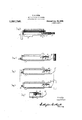
- Figure 1 is a plan View of my improved detecting mechanism
- Fig. 2 is a side elevation thereof
- ig. 3 is a vertical sectional view taken along the line 33 in Fig. 1;
- Fig. 4.- is a partial horizontal plan view taken along the line 4 4 in Fig. .2'
- Figs. '5 and 6 are views 7 but showing the parts in different positions
- Fig. 7. is a detail sectional View of a slight modification.
- This mechanism includes a stand or frame 10 havingassociated therewith an actuator 11 mounted upon a floating pivot 12 and having one end movable in a slot 13 (Fig. 3) formed in a bracket 14 fixed to the frame 10.
- a plunger 15 is slidable transversely of the slot .13 through a hole 16 in the bracket, said plunger being pivoted at 17 to an arm 18 mounted on a short rock shaft 19.
- the shaft 19 is carried in bearings secured to the frame 10, and at its opposite similar tb Fig. 4,
- a spring'23 is interposed between a collar 24 and one of the bearings of the shaft 19 and causes the arm 20 to yieldingly engage the left hand or front end of the s 21.
- the stand 22 is secured to the fra e 1.0 by a bolt 25 and may be vertically a justed thereon by an adjusting screw 26.
- the slide 21 is formed as a hollow shell, one end of which directly engages the arm 20. Near the rear or right hand end of the slide 21 is pivotally connected a detectin member 27, preferably of hard rubber or l ber and provided with shallow teeth on its outer face.
- a plunger 28 surrounded by a light coiled spring 29 is slidable in a bearing 30 in the slide 21, and engages the detector-27 as shown in Fig. 4, in which the detector 27 is in its normal position.
- the method of operation of my improved detector is extremely simple.
- the normal position of the slide 21 and detector 27 is shown in Fig. 5. This corresponds to the position of the plunger 15 shown in Figs. 1 and 2.
- the teeth on the end of the detector prevent the detector from sliding along the weft carrier, and the slide 21 is therefore pushed forward to the position shown in Fig. 4, in which position the plunger 15 is withdrawn from the path of the actuator.
- this construction provides an extremely simple detector, as the slide'21 has only a single movable element mounted thereon, and furthermore, the slide itself directly engages the arm 20, so that there are no connections between the parts subject to wear and consequent inaccuracy in operation.
- the detector 27 is also free to swing farther to the left as viewed in Fig. 6, so that the slide 21 will directly engage a misplaced shuttle. This arrangement preventsa misplaced shuttle from placing ex-- cessive strain upon the detector spring 29.
- a weft detecting mechanism comprising a stand, a slide movably mounted thereon, an actuator, a member controlling said actuator and normally positioned to render said actuator operative, connections between said member and said slide, a single detector movably mounted direct onsaid slide, and a spring yieldingly holding said detector in position toengage ,a weft carrier, said de tector and slide being movable in a straight line as a unit and in fixed relative position by engagement of said detector by a suflicient supply of weft on an active weft carrier,- and said detector being movable relativelyito said slide by engagement of said detector by a substantially exhausted weft carrier.
- a weft detecting mechanism having, in combination, an actuator, controlling devices including an arm, a slide directly engaging and moving said arm, a single detector directly pivoted to said slide, a plunger engagin said detector, a spring for said plunger, an means to adjust the tension of said spring, comprising a sleeve threaded in said slide and forming both a bearing for said plunger and an adjustable support for said spring.
- a weft detecting mechanism comprising a stand, a slide mounted thereon, said slide being positioned to directly engage a misplaced shuttle, a single detector pivoted between the upper and lower plates of said slide, an actuator, and connections through which said slide is effective to render said actuator inoperative when said slide is moved forward from normal position.
Description
E. H. RYON.
wan DETECTOR FoR Looms.
APPLICATION FILED MN. 2, 19 18.
Patented Apr. 20, 1920.-
2 sums-sun I.
E. H. RYON.
WEFT DETECTOR FOILLQOMS'. APPLICATION FILED IAN-2.1918.
1,337,73 Patented Apr. 20,1920.
2 SHEETS-SHEET 2.
UNITED STATES PATENT OFFICE.
EPPA H. RYON, OF WALTHAM, MASSACHUSETTS, ASSIGNOR TO CROMPTON & KNOWLES LOOM WORKS, OF WORCESTER, MASSACHUSETTS, A CORPORATION OF MASSACHU- SETTS.
WEFT-DETECTOR FOR LOOMS.
Specification of Letters Patent.
, Patented Apr. 20, 1920.
Application filed January 2, 1918. Serial No. 209,818. 1
To all whom it may concern:
Be it known that I, EPPA. H. RYoN, a citizen. of the United States, residing at Waltham, in the county of-Middlesex and State of Massachusetts,- haveinvented a new and useful Weft-Detector for Looms, of which the following isfia specification.
This invention relates particularly to that type of weft detecting mechanism by means of which substantial exhaustion of weft on the active weft carrier is ascertained. More specifically my invention relates to a class of such detectors in which a detecting member is pivotally supported and is so formed that it will swing upon its pivot only upon' engagement with a substantially exhausted weft carrier. It is the general object of my invention to improve and simplify the construction of such devices,.to the end that their operation may be made reliable and satisfactory.
With this general object in View, my invention relates to certain combinations of parts which will be hereinafter described and more particularly pointed out in the appended claims.
A preferred form of my invention shown in the drawings, in which Figure 1 is a plan View of my improved detecting mechanism;
Fig. 2 is a side elevation thereof;
ig. 3 is a vertical sectional view taken along the line 33 in Fig. 1;
Fig. 4.- is a partial horizontal plan view taken along the line 4 4 in Fig. .2'
Figs. '5 and 6 are views 7 but showing the parts in different positions, and
Fig. 7. is a detail sectional View of a slight modification.
I have shown my invention embodied in a weft detecting mechanism of the general type shown in my Patent No. 972,722 granted to me October 11, 1910'.
This mechanism includes a stand or frame 10 havingassociated therewith an actuator 11 mounted upon a floating pivot 12 and having one end movable in a slot 13 (Fig. 3) formed in a bracket 14 fixed to the frame 10. A plunger 15 is slidable transversely of the slot .13 through a hole 16 in the bracket, said plunger being pivoted at 17 to an arm 18 mounted on a short rock shaft 19. The shaft 19 is carried in bearings secured to the frame 10, and at its opposite similar tb Fig. 4,
end is provided with a second arm 20, positioned for engagement by a slide 21 mounted for longitudinal movement in a stand 22.- A spring'23 is interposed betweena collar 24 and one of the bearings of the shaft 19 and causes the arm 20 to yieldingly engage the left hand or front end of the s 21.
I The stand 22 is secured to the fra e 1.0 by a bolt 25 and may be vertically a justed thereon by an adjusting screw 26. The slide 21 is formed as a hollow shell, one end of which directly engages the arm 20. Near the rear or right hand end of the slide 21 is pivotally connected a detectin member 27, preferably of hard rubber or l ber and provided with shallow teeth on its outer face.
.A plunger 28 surrounded by a light coiled spring 29 is slidable in a bearing 30 in the slide 21, and engages the detector-27 as shown in Fig. 4, in which the detector 27 is in its normal position. I I
In F ig. 7 I haveshown a slight modification in which the plunger 28 is s'lidable in a sleeve 31. -The sleeve is threaded into the frame of'the slide 21 and is slotted at one end so that it. may be adjusted to vary the tension of the spring 29.
The method of operation of my improved detector is extremely simple. The normal position of the slide 21 and detector 27 is shown in Fig. 5. This corresponds to the position of the plunger 15 shown in Figs. 1 and 2. Whenever the detector 27 is engaged by a weft carrier having a supply of weft thereon, the teeth on the end of the detector prevent the detector from sliding along the weft carrier, and the slide 21 is therefore pushed forward to the position shown in Fig. 4, in which position the plunger 15 is withdrawn from the path of the actuator.
When, however, the supply of weft on the weft carrier is substantially-exhausted, the weft will no longer prevent, the sliding of the detector along the weft carrier, and the parts will assume the position shown in Fig. 6, the detector swinging about its pivot and the slide 21 remaining unmoved. The plunger 15 is thus left in the path of the actuator 11 which is thereby rendered operative to indicate a transfer.
It will be seen that this construction provides an extremely simple detector, as the slide'21 has only a single movable element mounted thereon, and furthermore, the slide itself directly engages the arm 20, so that there are no connections between the parts subject to wear and consequent inaccuracy in operation. The detector 27 is also free to swing farther to the left as viewed in Fig. 6, so that the slide 21 will directly engage a misplaced shuttle. This arrangement preventsa misplaced shuttle from placing ex-- cessive strain upon the detector spring 29.
It will be evident that changes and modifications may be made in m invention by those skilled in the art, wit out departing from the spirit. and scope thereof as set forth in the claims, and I do not wish to be otherwise limited to the details herein disclosed, but What I claim is 1. A weft detecting mechanism comprising a stand, a slide movably mounted thereon, an actuator, a member controlling said actuator and normally positioned to render said actuator operative, connections between said member and said slide, a single detector movably mounted direct onsaid slide, and a spring yieldingly holding said detector in position toengage ,a weft carrier, said de tector and slide being movable in a straight line as a unit and in fixed relative position by engagement of said detector by a suflicient supply of weft on an active weft carrier,- and said detector being movable relativelyito said slide by engagement of said detector by a substantially exhausted weft carrier.
2. A weft detecting mechanism having, in combination, an actuator, controlling devices including an arm, a slide directly engaging and moving said arm, a single detector directly pivoted to said slide, a plunger engagin said detector, a spring for said plunger, an means to adjust the tension of said spring, comprising a sleeve threaded in said slide and forming both a bearing for said plunger and an adjustable support for said spring.
3. A weft detecting mechanism comprising a stand, a slide mounted thereon, said slide being positioned to directly engage a misplaced shuttle, a single detector pivoted between the upper and lower plates of said slide, an actuator, and connections through which said slide is effective to render said actuator inoperative when said slide is moved forward from normal position.
In testimony whereof I have hereunto affixed my signature.
EPPA H. RYON.
Priority Applications (1)
| Application Number | Priority Date | Filing Date | Title |
|---|---|---|---|
| US209818A US1337726A (en) | 1918-01-02 | 1918-01-02 | Weft-detector for looms |
Applications Claiming Priority (1)
| Application Number | Priority Date | Filing Date | Title |
|---|---|---|---|
| US209818A US1337726A (en) | 1918-01-02 | 1918-01-02 | Weft-detector for looms |
Publications (1)
| Publication Number | Publication Date |
|---|---|
| US1337726A true US1337726A (en) | 1920-04-20 |
Family
ID=22780425
Family Applications (1)
| Application Number | Title | Priority Date | Filing Date |
|---|---|---|---|
| US209818A Expired - Lifetime US1337726A (en) | 1918-01-02 | 1918-01-02 | Weft-detector for looms |
Country Status (1)
| Country | Link |
|---|---|
| US (1) | US1337726A (en) |
-
1918
- 1918-01-02 US US209818A patent/US1337726A/en not_active Expired - Lifetime
Similar Documents
| Publication | Publication Date | Title |
|---|---|---|
| US1337726A (en) | Weft-detector for looms | |
| US2151199A (en) | Weft feeler device for looms for weaving | |
| US1378913A (en) | Feeler mechanism for looms | |
| US2050066A (en) | Convertible weft detector | |
| US1663934A (en) | Side-slip weft detector | |
| US1352536A (en) | Weft-detecting mechanism | |
| US1566697A (en) | Weft-detecting mechanism | |
| US1369478A (en) | Feeler mechanism for looms | |
| US1307024A (en) | Setts | |
| US1378909A (en) | Feeler mechanism for looms | |
| US1612573A (en) | Feeler mechanism for looms | |
| US2030688A (en) | Feeler mechanism for looms | |
| US1396671A (en) | Feeler mechanism for looms | |
| US1462554A (en) | Weft-detector mechanism | |
| US1651098A (en) | Weft detector for looms | |
| US1715992A (en) | Side-slipping weft detector for looms | |
| US1362117A (en) | Feeler mechanism for looms | |
| US1612099A (en) | Weft-replenishing mechanism | |
| US1633651A (en) | Weight-controlled detector for looms | |
| US1369482A (en) | Feeler mechanism for looms | |
| US1405451A (en) | Feeler mechanism for looms | |
| US1873183A (en) | Weft detecting mechanism for pick and pick looms | |
| US1387204A (en) | Feeler mechanism for looms | |
| US918645A (en) | Thin-place-detecting mechanism for looms. | |
| US1478264A (en) | Feeler mechanism for looms |