US133451A - Improvement in metal-rolling machines - Google Patents
Improvement in metal-rolling machines Download PDFInfo
- Publication number
- US133451A US133451A US133451DA US133451A US 133451 A US133451 A US 133451A US 133451D A US133451D A US 133451DA US 133451 A US133451 A US 133451A
- Authority
- US
- United States
- Prior art keywords
- plates
- carriages
- improvement
- shaft
- metal
- Prior art date
- Legal status (The legal status is an assumption and is not a legal conclusion. Google has not performed a legal analysis and makes no representation as to the accuracy of the status listed.)
- Expired - Lifetime
Links
- 238000005096 rolling process Methods 0.000 title description 6
- 102000004726 Connectin Human genes 0.000 description 1
- 108010002947 Connectin Proteins 0.000 description 1
- 238000010276 construction Methods 0.000 description 1
- 239000002184 metal Substances 0.000 description 1
- 238000010626 work up procedure Methods 0.000 description 1
Images

Classifications
-
- B—PERFORMING OPERATIONS; TRANSPORTING
- B21—MECHANICAL METAL-WORKING WITHOUT ESSENTIALLY REMOVING MATERIAL; PUNCHING METAL
- B21H—MAKING PARTICULAR METAL OBJECTS BY ROLLING, e.g. SCREWS, WHEELS, RINGS, BARRELS, BALLS
- B21H5/00—Making gear wheels, racks, spline shafts or worms
- B21H5/02—Making gear wheels, racks, spline shafts or worms with cylindrical outline, e.g. by means of die rolls
- B21H5/027—Making gear wheels, racks, spline shafts or worms with cylindrical outline, e.g. by means of die rolls by rolling using reciprocating flat dies, e.g. racks
Definitions
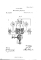
- Figure l a front view; Fig. 2, an end view; and in Fig. 3, a top view.
- This invention relates tothe construction of a machine for rolling tapers, more especially designed for small diameters.
- D filed in even date herewith, I have represented a pair of reciprocating plates for rolling shafting or rods of an equal diameter.
- This invention consists in the arrangement of a pair of adjustable flat plates, to which a reciprocating movement is imparted, these plates swinging from the center in an arc of a
- the surfaces of the said plates radiating from the said center will, acting upon a blank placed between them, work the said blank into a taper form, which, if extended, would run to a point at the said center, its largest diameter being the outer edge of the said plates.
- A is the frame of the machine, upon which, in suitable bearings A', a driving-shaft, B, is arranged to be driven bythe application of power thereto in any convenient manner, here, for convenience of illustration, represented as by a crank7 B1.
- C C1 are two reciprocating carriages, upon the meeting-faces of which are arranged plates a a', whose surfaces, vertically, are parallel to each other. These carriages C Cl-extend back in the form of arms C2 C, and are hung upon a shaft arranged in independent frames D D1, these frames arranged upon a common vertical center, D2, as seen in Figs.
- the said carriages are in connection with the driving-shaft B by means of cranks B1 and B2 and connectin g-rods B3 and B4, as seen in Fig. 1
- the plates reciprocate, and, by the turning of the cams F2 and F3 to force the wedges forward, the plates gradually but slowly approach each other; therefore, if a blank or rod be placed between the plates when first open, and allowed there to remain, it will be rolled between the plates until reduced in diameter corresponding to the distance between the two plates.
- the rod so introduced should be in a line radiating from the same common center before described hence, as the plates move in opposite directions with equal velocity, the rod will roll between the plates, but will not change its axial position.
- a leading-screw, P in connection with the carriage L1, is caused to revolve by means of two pawls, l?l l, actuated by eccentrics on the driving-shaft. Their movements, corresponding, respectively, to that of thercranks B1 B2, actV upon a ratchet, l, on a shaft, P4, which shaft carries a bevel-gear, P5, working into a corresponding gear, P6, on the leadingscrew I.
- a movement timed to correspond to the movement of the plates is imparted to the leadingscrew a movement timed to correspond to the movement of the plates.
- the blank to be rolled is secured in the mandrel and inserted between the reciprocating plates, and there held until rolled down to the diameterrequired, the cams F2 l?3 acting, as before described, to press the plates together.
- the action ofthe cams F2 F3 is reversed, the plates opened, the mandrel withdrawn, and a new blank introduced.
- the feeding device is not essential; but for ⁇ drawing down, a blank is introduced of sufficient length to extend beyond the inner edge of the plates, as denoted in broken lines, Fig. 8, this extension being sufficient for the drawing downrequired.
- a blank is introduced of sufficient length to extend beyond the inner edge of the plates, as denoted in broken lines, Fig. 8, this extension being sufficient for the drawing downrequired.
- a pair ot' reciprocating carriages, C C1 each provided with plates or workin g surfaces vertically parallel to each other, and tra-nsversely inclined to a common center, upon which common centerv the said carriages are hung, to each of which areverse reciprocating ⁇ movement is imparted, and provided with a mechanism, substantially such as described, to'cause the said working surfaces or carriages to gradually approach each other to roll the blank placed between them into a tapering form, substantially as described.
Landscapes
- Engineering & Computer Science (AREA)
- Mechanical Engineering (AREA)
- Heat Treatment Of Articles (AREA)
Description
b'i'ai Raming Machines.
Na, 333,6f5'. Patented Nov.2,13:z2
mummgm. C
& man! Af/LPHoTo-L/THOGHAFHIG cammeo/meis Pfwcsss.)
' circle.
U Nrrnn S'IArns essere rrrcn.
HENRY KELLOGG, O-F MILFOBD, CONNECTICUT.
IMPROVEMENT IN METAL-RLLING MACHINES.
Specification forming part of Letters Patent No. l, dated November 26,1872.
To all whom it may concern:
Be it known that I, HENRY KELLOGG, of Milford, in the county of New Haven and State of Connecticut, have invented a new Improvement in Machines for Bolling Tapers; and I do hereby declare the following, when taken in connection with the accompanying drawing and the letters of reference marked thereon, to be a full, clear, and exact description of the same, and which said drawing constitutes part of this specification, and represents, in-
Figure l, a front view; Fig. 2, an end view; and in Fig. 3, a top view.
This invention relates tothe construction of a machine for rolling tapers, more especially designed for small diameters. In my application marked D, filed in even date herewith, I have represented a pair of reciprocating plates for rolling shafting or rods of an equal diameter. In my present application I embody a similar principle of reciprocating plates, but arranged for rolling taper forms.
This invention consists in the arrangement of a pair of adjustable flat plates, to which a reciprocating movement is imparted, these plates swinging from the center in an arc of a The surfaces of the said plates radiating from the said center will, acting upon a blank placed between them, work the said blank into a taper form, which, if extended, would run to a point at the said center, its largest diameter being the outer edge of the said plates.
A is the frame of the machine, upon which, in suitable bearings A', a driving-shaft, B, is arranged to be driven bythe application of power thereto in any convenient manner, here, for convenience of illustration, represented as by a crank7 B1. C C1 are two reciprocating carriages, upon the meeting-faces of which are arranged plates a a', whose surfaces, vertically, are parallel to each other. These carriages C Cl-extend back in the form of arms C2 C, and are hung upon a shaft arranged in independent frames D D1, these frames arranged upon a common vertical center, D2, as seen in Figs. 2 and 4, so that while the said carriages will move freely up and down, swinging upon the shaft in the frame D D1, they may be turned from each other, constantly radiating from the said vertical point D2. Outsidev the platesn C C1 are arranged bearings E El for the support of the said carriages. These bearings, in like manner, by the arms E2 E3, extend back to the same shaft as their respective carriages, as seen in Fig. 3, and, in like manner, turned to the right and left upon the said center. To avoid friction between the carriages and their bearings, I arrange back of each carriage two or more rolls, d, as seenvin Fig. 3. These rolls are tapering toward the same common center before described, so as to make the velocity or movement the same both in the front and rear, and so as to roll freely between the carriages and their respective bearings. To retain the said vrolls in their proper relative position I apply to each end of the rolls a pinion, d, and to the corresponding edges of the carriage a rack, f, and a corresponding rack, a, to each of the bearings, as seen in Fig. 1. The pitch-line of the pinions and racks corresponds to the diameter of lthe rolls at that point, so that, the carriages moving as before described, the rolls revolve and work up and down between the carriages and their bearings, but always in a radial line from the same common center. In order to adjust the plates to a greater or less distance from each other, to produce a greater or less diameter, I arrange between each of the bearings E E andv the frame A a wedge, F F1, working to avoid friction between a roll, h, on the frame and roll m ou the bearing, as seen in Fig. 3. These wedges are actuated by cams F2 F3 in the rear, the said cams arranged upon vertical shafts F", which said shafts are caused to revolve by worms I on a shaft, I1, working in a toothed wheel, I2, on the said shafts F4, the said worms driven by intermediate gearing from the main shaft.
The said carriages are in connection with the driving-shaft B by means of cranks B1 and B2 and connectin g-rods B3 and B4, as seen in Fig. 1
hence as the driving-shaft revolves a vertical reciprocating movement is imparted to each as to open the plates to their fullest extent j As these wedges are forced forward the plates approach each other, and when` drawn back the plates separate.
and the parts of the machine which I have described being in connection, the plates reciprocate, and, by the turning of the cams F2 and F3 to force the wedges forward, the plates gradually but slowly approach each other; therefore, if a blank or rod be placed between the plates when first open, and allowed there to remain, it will be rolled between the plates until reduced in diameter corresponding to the distance between the two plates. The rod so introduced should be in a line radiating from the same common center before described hence, as the plates move in opposite directions with equal velocity, the rod will roll between the plates, but will not change its axial position. To thus introduce the rod, I arrange a mandrel, L, in a carriage, L1, which `moves in guides L2 to and from the plates,
the axial line of the said mandrel being radial from the before-mentioned common center. A leading-screw, P, in connection with the carriage L1, is caused to revolve by means of two pawls, l?l l, actuated by eccentrics on the driving-shaft. Their movements, corresponding, respectively, to that of thercranks B1 B2, actV upon a ratchet, l, on a shaft, P4, which shaft carries a bevel-gear, P5, working into a corresponding gear, P6, on the leadingscrew I. Thus is imparted to the leadingscrew a movement timed to correspond to the movement of the plates. The blank to be rolled is secured in the mandrel and inserted between the reciprocating plates, and there held until rolled down to the diameterrequired, the cams F2 l?3 acting, as before described, to press the plates together. When the required diameter is attained the action ofthe cams F2 F3 is reversed, the plates opened, the mandrel withdrawn, and a new blank introduced.
In this operation the feeding device is not essential; but for `drawing down, a blank is introduced of sufficient length to extend beyond the inner edge of the plates, as denoted in broken lines, Fig. 8, this extension being sufficient for the drawing downrequired. Thus is believed to be the best, and less liable to` cause the metal to iiake than the rolling of the blank without feeding. l
If desirable, a noduled or botryoidal surface, as described in my application B for a similar invention led in even date herewith,
may be given to the rolling surface.
I claim as my invention` l. A pair ot' reciprocating carriages, C C1, each provided with plates or workin g surfaces vertically parallel to each other, and tra-nsversely inclined to a common center, upon which common centerv the said carriages are hung, to each of which areverse reciprocating` movement is imparted, and provided with a mechanism, substantially such as described, to'cause the said working surfaces or carriages to gradually approach each other to roll the blank placed between them into a tapering form, substantially as described.
2. In combination with the subject-matter of the rst clause of claims, I claim a mandrel, L, arranged relatively to the said plates to` hold and support the blank or rod being rolled, substantially as specified.
3. In combination with the subject-matter of the rst clause of claims, I claim the feeding device, substantially such as described, carrying the said mandrel L, and to which a retreating movement is imparted, timed in its movement relatively to the movement of the plates, substantially as set forth.
. HENRY KELLOGG.
Witnesses:
J. H. SHUMWAY, A. J. Trnnr'rs.
Publications (1)
| Publication Number | Publication Date |
|---|---|
| US133451A true US133451A (en) | 1872-11-26 |
Family
ID=2202867
Family Applications (1)
| Application Number | Title | Priority Date | Filing Date |
|---|---|---|---|
| US133451D Expired - Lifetime US133451A (en) | Improvement in metal-rolling machines |
Country Status (1)
| Country | Link |
|---|---|
| US (1) | US133451A (en) |
Cited By (1)
| Publication number | Priority date | Publication date | Assignee | Title |
|---|---|---|---|---|
| US20040078315A1 (en) * | 2002-07-29 | 2004-04-22 | Montepeque Jorge Eduardo | Method for assessing a commodity price and assessment determined thereby |
-
0
- US US133451D patent/US133451A/en not_active Expired - Lifetime
Cited By (1)
| Publication number | Priority date | Publication date | Assignee | Title |
|---|---|---|---|---|
| US20040078315A1 (en) * | 2002-07-29 | 2004-04-22 | Montepeque Jorge Eduardo | Method for assessing a commodity price and assessment determined thereby |
Similar Documents
| Publication | Publication Date | Title |
|---|---|---|
| US133451A (en) | Improvement in metal-rolling machines | |
| US133452A (en) | Improvement | |
| US654590A (en) | Reduction to hollow wire of tubular shells of gold. | |
| US509730A (en) | Machine for forming projectiles | |
| US372747A (en) | Reversing rolling-mill | |
| US1368956A (en) | Rotary embossing-machine | |
| US103397A (en) | Improved machine for rolling metals | |
| US75893A (en) | Benj n w | |
| US119716A (en) | Improvement in machines for bending tires | |
| US149310A (en) | Improvement in machines for rolling tubing | |
| US119521A (en) | Improvement in machines for rolling tapering forms | |
| US149309A (en) | Improvement in machines for rolling tubing | |
| US137009A (en) | Improvement in the manufacture of bolts and rivets | |
| US397460A (en) | Hiram emery fuller | |
| US380577A (en) | Apparatus for making drills | |
| US685416A (en) | Spike-grooving machinery. | |
| US459752A (en) | Method of and apparatus for making tubing | |
| US133449A (en) | Improvement in machines for lining carriage-axle boxes | |
| US742645A (en) | Rolling-mill. | |
| US316135A (en) | Jewelers rolls | |
| US133453A (en) | Improvement in metal-rolling machines | |
| US53012A (en) | Improvement in machinery for rolling iron | |
| US382729A (en) | Stickee | |
| US388574A (en) | Assigfoe of one | |
| US230064A (en) | Gaeeet p |