US1306A - Machine for making sausages - Google Patents
Machine for making sausages Download PDFInfo
- Publication number
- US1306A US1306A US1306DA US1306A US 1306 A US1306 A US 1306A US 1306D A US1306D A US 1306DA US 1306 A US1306 A US 1306A
- Authority
- US
- United States
- Prior art keywords
- cylinder
- machine
- knives
- shaft
- hopper
- Prior art date
- Legal status (The legal status is an assumption and is not a legal conclusion. Google has not performed a legal analysis and makes no representation as to the accuracy of the status listed.)
- Expired - Lifetime
Links
- 235000013580 sausages Nutrition 0.000 title description 6
- 235000013372 meat Nutrition 0.000 description 10
- 239000000463 material Substances 0.000 description 8
- 210000001035 Gastrointestinal Tract Anatomy 0.000 description 6
- 241001125879 Gobio Species 0.000 description 2
- 238000010276 construction Methods 0.000 description 2
- 239000002184 metal Substances 0.000 description 2
- 230000000750 progressive Effects 0.000 description 2
- 238000004904 shortening Methods 0.000 description 2
- 238000006467 substitution reaction Methods 0.000 description 2
Images
Classifications
-
- B—PERFORMING OPERATIONS; TRANSPORTING
- B02—CRUSHING, PULVERISING, OR DISINTEGRATING; PREPARATORY TREATMENT OF GRAIN FOR MILLING
- B02C—CRUSHING, PULVERISING, OR DISINTEGRATING IN GENERAL; MILLING GRAIN
- B02C2/00—Crushing or disintegrating by gyratory or cone crushers
- B02C2/10—Crushing or disintegrating by gyratory or cone crushers concentrically moved; Bell crushers
Definitions
- the body of this machine within which the cutting is to be eected is a hollow cylinder which I usually make of sheetiron, fourteen inches long, and siX inches in diameter, deeming this a good general size.
- This cylinder is furnished with two heads, and is placed upon a suitable stand in a horizontal position. It is to be divided horizontally into two equal parts, and the upper part is to be hinged, or otherwise attached, to t-he lower part, so that it can be opened and closed at pleasure.
- each knife present-ing an oblique cutting edge to the meator other article to be cut.
- a cylindrical shaft which may be two inches and a half in diameter, is made to revolve within the cylinder, its gudgeons being supported by the two heads.
- To this shaft is attached a number of wings, or leaves, which are to pass between the respective knives, occupying, as nearly as may be, the whole space between them and the shaft and cylinder. There may be four such wings or leaves attached to the shaft, to pass between each pair of knives.
- the upper section of the cylinder is to be close down upon the lower, and held in place by suitable clasps.
- the meat is to be fed in through a hopper placed on the upper side of the cylinder for that purpose.
- This hopper is notattached directly to the cylindeigbut to a sliding shutter, which runs in grooves upon the cylinder.
- the object of this contrivance is to enable me to lengthen or shorten the machines at pleasure, and thus to regulate the cutting according to the fineness which it may be desired to give to the material. As it is required to be less iine the hopper is slid toward the delivering end, and the material is consequently exposed to the action of a smaller number of knives.
- FIG. 1 is a perspective view of the machine; Fig. 2 a cross section of it, and Fig. 3 the false head for shortening it when desired.
- A is one head of the cylinder within which revolves the shaft B, B.
- the upper section C, C, of the cylinder is shown as turned back for the purpose of showing the parts within it.
- a, a, ai are the knives, which are confined in place by wedges b', b, b, or by screws, or other proper means on the outside of the cylinder.
- the portion of them passing into the cylinder is shown at a, a, Fig. 2.
- c, c, c are the leaves, or wings which are attached to the shaft B, B, their planes forming an angle with the axis of the cylinder and filling the spaces between two contiguous knives, so as to force the material to be cut, in their ascent and descent, against the oblique edges of the knives a', a, Fig. 2, while they give it a progressive motion, proportion to their Obliquity, along the cylindrical body of the machine, toward the head A, where D, is the tube of delivery, upon which the gut to be stuffed is to be drawn.
- E is a longitudinal opening in the upper part of the cylinder, which is to be as wide as the bot-tom of the hopper F, and three or four times as long, so as to admit the sliding of the hopper toward or from the end A, of the machine.
- At, d is a part of the sliding shutter to which the hopper is attached, and which slides between ledges e, e.
- the false head Fig. 3, consists of two semicircular plates of metal f, f, which fit the interior of the cylinder A, C, and are hollowed out at g, g, so as to it the shaft ⁇ B, B. Their use has been already explained, and, when employed, they occupy the place of two of the knives a', a.
- Knives for example, have been placed Within a hollow cylinder, and around a revolving shaft within it, the latter lhaving been placed obliquely for the purpose of forcing the cut material toward one end of the cylinder.
- the substitution, however, of the leaves, or wings, c, c, for such knives is a decided improvement, as they insure the more perfect cutting of the article to be operated upon, by forcing it against the fixed knives within the cylinder.
Description
No. 1,306. PATENTED AUG. 29, 1839'.
Gr. D. METTETAL.
.. SAUSAGB MAKER.
UNITED STATES PATENT OFFICE.
G. D. METTETAL, OF PITTSBURGH, PENNSYLVANIA.
MACHINE FOR MAKING SAU'SAGEAS.
Specification of Letters Patent No. 1,306, dated August 29, 1839.
To all whom t may concern 1 Be it known that I, Gr. D. METTETAL, of the city of Pittsburgh, in the State of Pennsylvania, have invented an Improved Machine for Cutting Sausage-Meat and Stuffing Sausages, whichI denominate the Sausage-l\/Iakers;7 and I do hereby declare that the following is a full and exact description thereof.
The body of this machine within which the cutting is to be eected is a hollow cylinder which I usually make of sheetiron, fourteen inches long, and siX inches in diameter, deeming this a good general size. This cylinder is furnished with two heads, and is placed upon a suitable stand in a horizontal position. It is to be divided horizontally into two equal parts, and the upper part is to be hinged, or otherwise attached, to t-he lower part, so that it can be opened and closed at pleasure. I insert two rows of knives in the lower portion of the cylinder. These knives pass into the cylinder through slots or openings just below each edge of its lower segment, and they may be three fourths of an inch apart, more or less, as may be preferred. They are to be secured in their places by wedges, or by other suitable means, on the outside of the cylinder, admitting of their being readily removed and replaced. The portion within the cylinder is of a triangle form, each knife present-ing an oblique cutting edge to the meator other article to be cut. A cylindrical shaft, which may be two inches and a half in diameter, is made to revolve within the cylinder, its gudgeons being supported by the two heads. To this shaft is attached a number of wings, or leaves, which are to pass between the respective knives, occupying, as nearly as may be, the whole space between them and the shaft and cylinder. There may be four such wings or leaves attached to the shaft, to pass between each pair of knives. They are set spirally into the shaft, and their planes stand obliquely with its axis, forming sections of the thread of a screw, each being inclined in the same direction, so as to carry the meat, or other article, from the feeding to the delivering end of the machine. The meat, when cut, passes out through a tube at one end of the machine, and when it is to be stued into gut, said gut is to be drawn on to the tube, as in other sausage machines.
Vhen the machine is to be used the upper section of the cylinder is to be close down upon the lower, and held in place by suitable clasps. The meat is to be fed in through a hopper placed on the upper side of the cylinder for that purpose. This hopper is notattached directly to the cylindeigbut to a sliding shutter, which runs in grooves upon the cylinder. The object of this contrivance is to enable me to lengthen or shorten the machines at pleasure, and thus to regulate the cutting according to the fineness which it may be desired to give to the material. As it is required to be less iine the hopper is slid toward the delivering end, and the material is consequently exposed to the action of a smaller number of knives. There is an opening in the upper section of the cylinder, which is covered by the slidino` shutter, t'o admit of this arrangement. hen the machine is shortened a false head is put into the cylinder, to permit the passing of the meat back into the unoccupied portion of the machine.
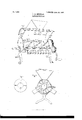
In the accompanying drawing Figure 1 is a perspective view of the machine; Fig. 2 a cross section of it, and Fig. 3 the false head for shortening it when desired.
A is one head of the cylinder within which revolves the shaft B, B. The upper section C, C, of the cylinder is shown as turned back for the purpose of showing the parts within it.
a, a, ai, are the knives, which are confined in place by wedges b', b, b, or by screws, or other proper means on the outside of the cylinder. The portion of them passing into the cylinder is shown at a, a, Fig. 2.
c, c, c, are the leaves, or wings which are attached to the shaft B, B, their planes forming an angle with the axis of the cylinder and filling the spaces between two contiguous knives, so as to force the material to be cut, in their ascent and descent, against the oblique edges of the knives a', a, Fig. 2, while they give it a progressive motion, proportion to their Obliquity, along the cylindrical body of the machine, toward the head A, where D, is the tube of delivery, upon which the gut to be stuffed is to be drawn.
E, E is a longitudinal opening in the upper part of the cylinder, which is to be as wide as the bot-tom of the hopper F, and three or four times as long, so as to admit the sliding of the hopper toward or from the end A, of the machine.
at, d, is a part of the sliding shutter to which the hopper is attached, and which slides between ledges e, e.
The parts shown in Fig. 2, are designated by the same letters of reference as those marked on the same parts in Fig. 1.
The false head, Fig. 3, consists of two semicircular plates of metal f, f, which fit the interior of the cylinder A, C, and are hollowed out at g, g, so as to it the shaft` B, B. Their use has been already explained, and, when employed, they occupy the place of two of the knives a', a.
I am aware that machines for cutting sausage meat, and other articles, have been constructed in a manner somewhat similar to that above described. Knives, for example, have been placed Within a hollow cylinder, and around a revolving shaft within it, the latter lhaving been placed obliquely for the purpose of forcing the cut material toward one end of the cylinder. The substitution, however, of the leaves, or wings, c, c, for such knives is a decided improvement, as they insure the more perfect cutting of the article to be operated upon, by forcing it against the fixed knives within the cylinder.
What I ela-im, therefore, in the cutting part of this machine, as of my invention, and desire to secure by Letters Patent, is-
l. The aflxing the knives a, a, by passing them through slots in the lower section of the cylinder, and securing them in place by wedges b, b, on the outside of the cylinder, thus admitting of their ready removal for sharpening, and their perfect adjustment in their places.
2. I claim the arrangement for shifting the hopper, so as to lengthen or shorten the v machines at pleasure, and in combination therewith, the employment of the false head, as described; and I will here remark that instead of placing the hopper upon a sliding shutter, it may be placed upon a plate which may be aiiixed on the top of the machine by screws, clasps, &c. I do not intend, therefore, to limit myself to the precise mode of construction herein described, but to vary this as I may think proper while the in-A Gr. D. METTETAL.
Witnesses THos. I). JONES, ISAAC BABBITT.
Publications (1)
| Publication Number | Publication Date |
|---|---|
| US1306A true US1306A (en) | 1839-08-29 |
Family
ID=2061592
Family Applications (1)
| Application Number | Title | Priority Date | Filing Date |
|---|---|---|---|
| US1306D Expired - Lifetime US1306A (en) | Machine for making sausages |
Country Status (1)
| Country | Link |
|---|---|
| US (1) | US1306A (en) |
-
0
- US US1306D patent/US1306A/en not_active Expired - Lifetime
Similar Documents
| Publication | Publication Date | Title |
|---|---|---|
| US1306A (en) | Machine for making sausages | |
| US196456A (en) | Improvement in nail-assorters | |
| US475367A (en) | Germann | |
| US101130A (en) | Improvement in paper-files | |
| US11706A (en) | Sausage-sttjefer | |
| US320326A (en) | Machine for polishing and sorting nuts | |
| US51891A (en) | Improvement in machinery for oiling wool | |
| US61856A (en) | Enos s | |
| US645450A (en) | Machine for assorting tobacco-tags. | |
| US200361A (en) | Improvement in bark-cutting machines | |
| US1161001A (en) | Ring-straightening mechanism. | |
| US280380A (en) | Machine for molding book-backs | |
| US13449A (en) | l seymour | |
| US3509A (en) | Improvement in sausage-meat cutters | |
| US167788A (en) | Improvement in smut-mills | |
| US55760A (en) | Improved sausage-stuffer | |
| US465302A (en) | Horse-collar-stuffing machine | |
| US68144A (en) | Improvement in machines foe making match-splints | |
| US312672A (en) | Half to edwin f | |
| US2815A (en) | Sausage-machine | |
| US79085A (en) | dille | |
| US102837A (en) | Improvement in vegetable-cutter | |
| US65074A (en) | Grain cleaner | |
| US58156A (en) | Improvement in machinery for coiling springs | |
| US46735A (en) | Improved machine for cutting the curd of cheese |