A. SEELEY.
APPARATUS FOR ATTACHING YARN T0 SPINDLES. APPLICATION FILED MAR. 16, 1916.
1,274,792. Patented Aug. 6, 1918.
ALFRED SEELEY, or'noennnm, nnemmn.
APPARATUS FOR ATYTACI-IINGIYARN TO srmnnns.
To all whom it may concern:
Be it-known thatI, ALFRED,
.; United Kingdom of Great Britain and Ireland, and resident of Melrose House Bentmeadows, Rochdale, in. the county lowing is a specification.
This invention relates to sleeves, for holding .yarns or threads attached to spindles b receiving coils of yarn or. thread wound be ow orbeyond the ends" of completed cops. or bobbins or other, bodies of or holding yarn so that after the.
completed cops orbobbins or; other-bodies have been dofi'ed from the spindles theyarns.
or threads rem'ainattached to the spindles in readiness for the windingof fresh. cops; bobbins .or other bodies tobebegun as soon as the travelers rails -or other yarn guiding} means are brought to proper position and either forthwith in the case of yarns or threads wound upon bare? spindles or after the application of fresher empty paper or other tubes or bobbins orabodies to the spin dles in other cases.
In this method of tamin ams} r.
threads tospindles the portions of yarn or thread wound upon the parts of or'providedi I upon the spindles to receivethem are usually allowed to accumulate thereon and removed from time to time.- 1. I In this method use has heretofore beenmade'of tubes or collarsorbraids applied to-spindles to be driven by friction against:v parts thereof and also of tubes or collars or 1 braids engaged with bobbins or-spools soi'as to turn therewith and so with the spindles carryingsuch spools or bobbins or connected with spindles as by being fixed-upon and-so? I be easily removed from and applied to spinmadeito turn with them, in order thatpor- .tions of yarn or threa'd-may be wound upon such'tubes or collars or braids as aforesaid and in somejcases such tubesor' collars or braids. have been removable from the spindlesand'some of such tubes or i'collars or q cordlng to this invention may-'bemadeof braids have been .formed of-sheet-Emetal.
from their interior passages through and to Specification of Letters Patent. f Patented Application filed ath 16, 1916. serial m. 84,610.
, SEELEY, machine maker, a subject of the King of the 0%- Lancaster, England, have invented new and useful Improvements in'Apparatus for At taching Yarn to Spindles, of which the foldetachable the spindles are used.
the exterior circumferences of their circumferentlal portlons and are also provided with parts to enter into positive engagement; .with drlving parts upon the spindles. and
in comparison with the devices heretofore provided for a like purpose are more easily n g. 6, 1191s.
stripped of accumulations of yarn or thread by reason of allowing free passage of blades for cuttlng off the accumulations of yarn or thread and are more'readily applied to and taken 01f the spindles, although when ap plied to the spindles, they revolvew-ith certainty'along with the parts to which they are applied. a
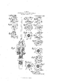
In: the accompanyin drawings-in which the same letters of rei erence are employed to indicate corresponding parts in all the figures, examples of sleeves provided ac- ,cording to thisfinvention are shown byway ;of illustration. a
v Figure 1 is a side elevation oi? one form ofsleeve and Figs. 2 and 3 are sections taken respectively on the planes indicated by the, lines A A and B B of Fig. 1, and
Fig. shows a sleeve of this form in longitudlnal section applied .to aspindle of a' Warp pirning machine. Fig. 5 is a side elevation and Fig. 6 is a plan of a second form of sleeve and Fig. 7 is' a section taken on;
theplane indicatedby the line C G of, Fig.
5. 'Fig. 8 is asideelevationgand Fig. 9 is,
a plan of a third form of a sleeve and Fig.
5 10 is a section taken onthe plane indicated by the line DD of Fig. 8. Figs. 11 and 12 are side elevations at right angles to one another and Fig. 13' a plan of-a fourth form ofsleeve. Figs. 14 and 15 area side elevation and plan of a fifth form of sleeve. I
Sleeves provided according to this invention areprefer'ably madelightand to fit easily upon the, spindles with which they are intended to be used so that they may dles even though such spindles should only just be within practicable reach ofthe op.-
eratives in chargeof the machinesin which Sleeves provided for use with spindles t.
thin metal cast, stampedor spun qorothe'rwisevbrought into shape or built up of parts The sleeves may be-made to'engage the-spindles bybeing provided with indentations one or more in each caseto engage into flats. or notchesfornied in'the spindles or may be provided with spring tongues or prongs to enter nicks or notches or holes in the spindles or over the edges'otfiangesor plates upon the spindles or the portions of metal at the sides of the gaps or nicksma'y be made to enter nicks or notches in the spindles. Each sleeve may be adapted to engage the spindle with which itnia-y be used at oneplace or two or more as may be desirable in each case."
Sleeves'provided according 'to this invention ma ybe provided with parts'to engage bobbins or otherjbodies to be mounte'd'upon the spindles with which the sleeves may be The collar 0 is provided with four flat faces d at equal intervals around its upper-part.
three being shown, and is circular in it's lower part c and the b'arr'el'a is formed internally witha' square hole 7 in its upper part and with cylindrically curvedwalls g in its lower part, the tool used in forming the angles of the square hole 7' being made forconvenience to form grooves h in the wall of a circular hole, and the walls of the-square hole f and the cylindrical'lycurved" walls 9- fitting easily against respectivelythe flat faces at and the circular part c of the collar 0. The barrel a is formed with a lower flange 71 to bearon the flange j of the spindle blade 5 and with an upper flange 79' to serve as-a stopto limit the distance to which paper tubes or the like can be pushed A nick" Z is formed'through the barrel a at oneside and onto the spindle blade 5.
through each" of the flanges i Into allow passage to the bladeof a knife or other tool to be used in cutting threads from the barrel a.
Yarn or thread may be'wound' upon'the' barrel a before the'co nmencement of a'pirn andbetween the completion'of one p rn' and thecomrnencement otthe next and the accumulation of yarn or thread on the barrel 0 may be cut ofi from time to time.
In the'sleeve shown in Figs. 5 and .6 and 7, the barrel 0 andflanges i 76 are all formed of thin metal stamped, spun' or otherwise shaped andthebarrel a iSTfOITDd with two indentations m forming- 'pIO]BOt10n$ n in its interior in the former chords of acircle wardly. turned rim 0 around its ClLCH111f6lJ-.
ence.
In th e'sleev e shown in F igs. 8, 9, and 10 the barrel a and upper flange are formed of one piece of thininetal stamped,spu n or otherwiseshaped and the" lowerflange is formed of another piece of metal stamped,- spun'or otherwise shaped with ah'ole to 're ceive the barrel a and a downwardly turnedrim 0 around its circumference. The barrel a is formed'withindentationsfin'like those-- of the bar-rel-c'shown'in Figs. 5; -6 and 7 and also with" ears pby which the barrel may be retained in the hole otthefianget The bafrre'l'a and flange 7a and-the flange areforme'd with nick's Z which are brought together when the barrel 0 is secured to the flange 11 so as to'serve as one niclrl for the passage of a knife blade or other tool for cutting threads from the sleeve.
The sleeveshown in Figs. 11, 12'and' 13 is "similar to'that shown in Figsp5; 6 and? except in that it has' 'no indentations or rinro but is provided witha spring tongue 9 at one side-cut'on three sides from and" remaining attached by its "fourth side to the metal of the' barrel a. g is intended' toengage by ressinga ainst a fiat or'enteri'ng a grooveupon'or in" the collar orother part'ofor provideduponthe spindle blade to receiye" the sleeve."
The sleeve shown in Figs; l4c'and 15 is similar to thatshow'n in Figs." 5, (Sand 7 ex'cept'in that it'h'as no indentation 'm; or riin' 0 but is'pr'ovided with" an inwardly di'-' rected projection-r formedon thebarrel a. by part of theinetaldisplaced in theforma tion of the nick Z being turned inward, the" projection" 17 being intended to enter" a groovein the collar" or other'part' of" orprovided upon the spindle blade to" receive the sleeve;
The portions of yarn orthrea'd woundupon sleeves provided according} to this in vention may be removed therefrom'from time'to'ti'meas may be convenient as by the use" of knives-or hooks withcutting edges:
If; with a" number of similar spindles-ina machine each provided with" adetachable The spring tongue sleeve provided according to "thisinvention',
a similar sleeveor'siinilarsleevesin excessof the" number of spindles be providedand of sleeves and the application of another from and to a spindle or group or set of spindles.
What I claim is: 1. A detachable sleeve of the character described for application. to a spindle and com an interior passage and a gap or nick which extends entirely through the sleeve from end to end from the interior passage through the circumferential portions to the circumferences thereof and having engaging faces in its interior parts adapted to bear against corresponding engaging faces upon the spindle. I
3. A detachable sleeve of the character described for application to a spindle and comprising circumferential portions having Copies of this patent may be obtained for an interior passage and a gap or nick which extends entirely through the sleeve from end to end and from the interior passage through the circumferential portions to the circumference's thereof and having formed within the upper part of the interior passage engaging faces adapted to enter into positive engagement with corresponding engaging faces upon the spindle.
4:. A spindle with engaging faces and a A detachable sleeve for application to such spindle and comprising circumferential pmtions having an interior passage to receive part of the spindle and a gap or nick which extends entirely through the sleeve from end to end and from the interior passa 6 through the circumferential portions to t e circumferences thereof and having engaging faces in its interior parts adapted to bear against theengaging faces upon the spindle.
In testimony that I claim the foregoing as my invention, I have signed my name in presence of two witnesses-this twenty-fourth day of February 1916.
ALFRED SEELEY;
Witnesses:
' GEORGIANA F. RHIND,
HOWARD GHEATHAM.
five cents each, by addressing the Commissioner of Patents, Washington, D. 0.