US1252182A - Oil-distributer for internal-combustion engines. - Google Patents
Oil-distributer for internal-combustion engines. Download PDFInfo
- Publication number
- US1252182A US1252182A US15378917A US15378917A US1252182A US 1252182 A US1252182 A US 1252182A US 15378917 A US15378917 A US 15378917A US 15378917 A US15378917 A US 15378917A US 1252182 A US1252182 A US 1252182A
- Authority
- US
- United States
- Prior art keywords
- intake
- engine
- oil
- contact
- magneto
- Prior art date
- Legal status (The legal status is an assumption and is not a legal conclusion. Google has not performed a legal analysis and makes no representation as to the accuracy of the status listed.)
- Expired - Lifetime
Links
Images

Classifications
-
- F—MECHANICAL ENGINEERING; LIGHTING; HEATING; WEAPONS; BLASTING
- F16—ENGINEERING ELEMENTS AND UNITS; GENERAL MEASURES FOR PRODUCING AND MAINTAINING EFFECTIVE FUNCTIONING OF MACHINES OR INSTALLATIONS; THERMAL INSULATION IN GENERAL
- F16H—GEARING
- F16H57/00—General details of gearing
- F16H57/04—Features relating to lubrication or cooling or heating
- F16H57/048—Type of gearings to be lubricated, cooled or heated
- F16H57/0482—Gearings with gears having orbital motion
- F16H57/0483—Axle or inter-axle differentials
Definitions
- This invention relates to an improved oil distributor for internal combustion engines of the type wherein the magneto for the engine is mounted upon the engine flywheel within the crank case of the engine with a magneto contact mounted upon the transmission cover of the engine to cooperate with the magneto.
- the invention has as its primary object to provide a distributor employing a contact mounting forming an intake adapted for connection to the transmission cover and provided with a scoop to extend through the opening for the magneto contact for collecting oil thrown up by the magneto and flywheel and delivering said oil into the intake to be distributed at the forward end of the crank casing for maintaining a circulation of oil within the said casing and effectually lubricating the engine.
- the invention has as a further object to provide an arrangement wherein the contact mounting will support the magneto contact employed with the said contact extending through the usual opening in the transmission cover to cooperate with the magneto.
- the invention has as a still further object to provide an improved construction of ma gneto contact and wherein the said contact may, as in the instance of the contact now employed upon engines of the abo e described type, be readily removed to be cleaned.
- a further object of the invention is to provide an arrangement wherein the contact mounting can be disconnected from the transmission cover only after the magneto contact has been detached from the said mounting so that the danger of breaking the magneto contact which would be incident to bodily disconnecting the intake with the contact from the transmission cover will be removed.
- the invention has as a further object to provide an improved discharge terminal for the distributer and wherein the'said terminal Specification of Letters Patent Patented Jan. 1, 1918.
- the invention has as a still further ob ject to so form the discharge terminal of the distributer that the said terminal may be connected to the crank case by a bolt securing the front cylinder cover of the engine to the case.
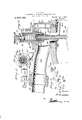
- Figure 1 is a side elevation showing my improved distributer applied to a conventional type of internal combustion engine
- Fig. 2 is a transverse sectional view particularly showing the manner in which the discharge terminal of the distributer is con nected with the crank case of the engine as well as the manner in which the said terminal is formed to enter through one of the bolt holes in the said crank case.
- Fig. 3 is a detail view showing the connection between the discharge terminal of the distributer and the pipe from the contact mounting connected thereto,
- Fig. 1 is a sectional view on an enlarged scale particularly showing the contact mounting and the arrangement of the magneto contact thereon
- Fig. 5 is a transverse sectional view on the line 55 of Fig. 1, particularly showing the construction of the magneto contact, and
- Fig. 6 is a detail perspective view of the discharge terminal of the distributer.
- FIG. 1 illustrated the invention in connection with a conventional type of in ternal combustion engine 10 having a crank casing; 11, a transmission cover 12 and a front cylinder cover 13.
- the front cylinder cover fits over the forward bearing 14; for the crank shaft of the engine and is connected to the crank casing by bolts 15 arranged at opposite sides of the crank shaft to extend through the bearing, and also by bolts 16 extending through the lateral extremity, and gravitatcs within the casing :1 toward its rear extremity to flow into the oil collecting chamber 18 formed to receive the flywheel of the engine.
- Connected to the flywheel is the magneto indicated in dotted lines at 19 in. Fig.
- the magneto and fiywheel are mounted to rotate through the oil in the chamber 18 for splashing the oil within the crank casing and maintaining the engi 1'3 lubricated.
- a charge pipe 23 communicating with the said chamber.
- Extending through the bottom wall of the body into the chamber 22 is a scoop which is overturned to engage with the said wall or is otherwise secured thereto.
- the scoop 2a is, as particularly shown in Fig. of the drawings, formed with a cylindrical inner terminal extending down- Wardly from the body of the intake and is then contracted to provide a flattened laterally curved intake pipe or mouth 25.
- the bottom of the body 21 of the intake is formed to seat fiat upon the transmission cover 12 over the opening 20 therein with the scoop 2 extending through the said opening.
- Detachably connecting the intake body with the transmission cover are a plurality of bolts 26 loosely fitted through suitable radial enlargements 27 on the body 21 of the intake and screw threaded into the transmission cover 12.
- Three of the bolts 26 are preferably employed and in this connection, attention is directed to the fact that the conventional magnet contact usedupon an engine of the herein described character is secured. to the transmission cover 12 to extend through the opening 20 by a similar number of bolts.
- the bolts 26 are formed to engage in such bolt openings so that no modification whatever will be required i the transmission cover 12 in ,order that the intake may be connected thereto, the scoop 24ibeing, at its inner extremity, of a diameter to fit snugly through the opening 20 without the necessity of enlarging the said opening.
- the body of the intake is thus fixed upon the transmission cover 12 by the bolts 26 with the inner terminal of the scoop extending slightly away from 1 the inner face of the transmission cover at its upper side and curving laterally to terminate directly over the magneto 19 of the engine.
- the magneto contact Arranged upon the contact mounting or intake body 21 is the magneto contact.
- This contact includes a cylindrical plug body 28 of suitable insulating material. Adjacent its inner extremity, the plug body is formed with an annular shoulder 29 and surrounding this shoulder is a nut 30 formed, at its inner extremity, with a flange 21 engaging beneath the said shoulder and rotatably con necting the nut with the plug body.
- the nut is screw threaded through the top wall of the body 21 of the intake for detachably connecting the contact therewith and at its outer extremity is formed with a radial flange 82 overhanging the bolts 26. Consequently, these bolts cannot be removed until after the nut 30 has been displaced for disconnecting the magneto contact from the intake. Breaking of the magneto contact by bodily removing the intake with the contact from the transmission cover is accordingly rendered impossible.
- a sleeve 33 Fitted through the plug body 28 is a sleeve 33 provided at its upper extremity with a flange 3% engaging over the upper end of the plug body with the sleeve overturned at its lower extremity to engage the lower end. of the plug body for connecting the sleeve thereto.
- a binding post 35 Upstanding from the upper terminal of the sleeve is a binding post 35 upon which is screw threaded a nut 36 and preferably interposed between the said nut and the upper end of the sleeve, is a resilient locking washer 37.
- Slidably mounted within the sleeve 33 is an electrode arranged to project freely through the scoop 2st to cooperate with the magneto.
- This electrode includes a cylindrical body 238 of suitable insulating material and fitted through the said body is a contact member or rod 39.
- This rod at its lower extremity, is formed with a preferably conical head 10 overhanging the lower terminal of the body 88 to cooperate with the magneto 19 and, at. its upper extremity, is screw threaded to receive a. nut 41 detachably connecting the rod with the electrode body.
- the upper terminal of the rod is preferably overturned against the nut or the nut is fixed upon the red by solder, as indicated at 42, to prevent the accidental displacement of the nut.
- the nut f-ll is formed with an undercut shank 43 and connected, at its lower extremity, to the said shank is a helical spring is arranged within the sleeve 33 and increased in diameter toward its upper extremity to engage with an inwardly extending flange 45 formed on the said sleeve.
- the spring 4:4: will thus act to urge the electrode downwardly to contact with the mag: neto with the spring adapted to normally maintain the electrode within the sleeve 33 when the magneto contact is removed from the intake. Furthermore, this spring is, as will be observed, arranged to establish electrical connection between the electrode and the binding post 35.
- a pipe 46 Connected to the outer extremity of the discharge pipe 23 is a pipe 46, the adjacent terminal of which is flared to seat against the outer end of the discharge pipe and is joined thereto by a nut or union 47 screw threaded upon the discharge pipe.
- the pipe 46 extends from the intake forwardly and downwardly along one side of the engine, as particularly shown in Fig. 1 and is connected, at its forward extremity to a discharge terminal 48.
- the adjacent end of the pipe 46 is flared to seat against the inner end of the discharge terminal and is connected thereto by a nut or union 49 screw threaded upon the said terminal.
- the discharge terminal 48 is in the nature of a hollow casting and, at its outer extremity, is formed with a downwardly and laterally directed discharge end 50. Fitted into the discharge end 50 of the discharge terminal is a nipple 51 around which is arranged a gasket 52. Projecting laterally from one side of the discharge terminal, is an extension 53 formed with a sleeve 54.
- the discharge terminal 48 is, as particularly shown in Fig. 2 of the drawings, arranged adjacent the forward extremity of the crank casing 11 at one side of the cover 13.
- one of the bolts 15 as well as one of the bolts 16 is removed.
- the sleeve 54 is then fitted over the bolt opening of the bolt l6 soremoved when abolt 55 is fitted through the said sleeve and through the said bolt opening for rigidly connecting the dis chargeterminal with the crank casing, with the discharge end 50 of the said terminal fitting over the bolt opening of the bolt 15 removed.
- the nipple 51 is formed to project .into this latter bolt opening with the gasket 52 seating against the adjacent face of the cover 13 for establishing a t ghtjoint between the discharge terminal and the said cover with the nipple establishing communication between the discharge terminal and the interior of the crank casing.
- I provide an arrangement wherein the oil will be distributed from the chamber 18 to the forward extremity of the crank casing and a constant circulation of oil maintained to effectually lubricate the engine while running.
- My present invention therefore, comprehends a particularly eflicient construction for the purpose set forth and an arrangement tending to prolong the life of the engine through a superior lubrication thereof.
- An oil distributor for internal combustion engines having a magneto for the engine mounted upon the engine flywheel, said distributer including a magneto contact mounting connected to the crank case of the engine over the flywheel and forming an intake, a scoop extending from the said intake and communicating interiorly of the casing for collecting oil thrown up by theflywheel and directing such oil into the intake, and a discharge terminal connected with the intake and communicating with the crank case of the engine at the extremity thereof opposite the said fly wheel.
- An oil distributer for internal combustion engines having a magneto for the engine mounted upon the engine flywheel, said distributer including a magneto contact mounting connected with the crank case of the engine over the flywheel, a scoop extending from the said intake and provided at its inner extremity with a reduced intake pipe communicating interiorly of the crank case of the engine for collecting oil thrown up by the flywheel and directing such oil into the intake, and a discharge terminal connected with the intake and communicating with the crankcase of the engine at the extremity thereof opposite the said flywheel.
- An'oil distributor for internal combustion engines having a magneto for the en-. gine mounted upon the engine flywheel, said distributer including a contact mounting having a hollow body forming an intake and provided with an oil receiving chamber, a scoop entering through the bottom wall of the body into the said chamber and communicating interiorly of the crank casing for collecting oil thrown up by the flywheel and directing such oil into the said chamber, a discharge pipe leading from the saidchamher, and a discharge terminal connected with the said pipe and communicating with the crank case of the engine at the extremity thereof opposite the said flywheel.
- An oil distributer for internal combustion engines having a magneto for the engine mounted upon the engine flywheel, said distributer including a contact mounting providing an intake, a scoop extending from the intake and communicating interiorly of the crank casing for collecting oil thrown up by the flywheel of the engine and directing such oil into the intake, a discharge terminal communicating with the crank casing of the engine at the extremity thereof opposite the flywheel and connected with said intake, and a contact arranged upon the said mounting to cooperate with the magneto.
- An oil distributer for internal combustion engines having a magneto for the engine mounted upon the engine flywheel, said distributer including a contact mounting providing an intake, a scoop extending from the intake and communicating interiorly of the crank casing for collecting oil thrown up by the flywheel of the engine and directing such oil into the intake, a discharge terminal communicating with the crank casing of the engine at the extremity thereof opposite the flywheel and connected with said intake, and a contact arranged upon the said mounting to cooperate with the magneto, said contact including a plug body connected with the said mounting, an electrode slidable with respect to the plug body, and means for urging the electrode outwardly upon the plug body to operatively contact with the magneto.
- An oil distributer for internal combustion engines having a magneto for the engine mounted upon the engine flywheel, said distributer including a contact mounting providing an intake, a scoop extending from the intake and communicating interiorly of the crank casing for collecting oil thrown up by the flywheel of the engine and directing such oil into the intake, a discharge terminal communicating with the crank casing of the engine at the extremity thereof opposite the flywheel and connected with said intake, and a contact arranged upon the said mounting to cooperate with the magneto, said contact including a plug body, an electrode slidable with respect to the plug body, and yieldable means connecting the electrode with the plug body and normally urging the said electrode outwardly upon the plug body to operatively contact with the magneto.
- An oil distributer for internal combustion engines having a magneto for the engine mounted upon the engine flywheel, said distributer including a contact mounting providing an intake, a scoop extending from the intake and communicating interiorly of the crank casing for collecting oil thrown up by the flywheel of the engine and directing such oil into the intake, a discharge terminal communicating with the crank casing of the engine at the extremity thereof opposite the flywheel and connected with said intake, and a contact arranged upon the said mounting to cooperate with the magneto, said contact including a plug body, an electrode slidable with respect to the plug body, a binding post carried by the plug body, and means establishing electrical connection between the electrode and the said binding post and normally urging the electrode outwardly upon the plug body to operatively contact with the magneto.
- An oil distributer for internal combustion engines having a magneto for the engine mounted upon the engine flywheel, said distributer including a contact mounting providing an intake, a scoop extending from the intake and communicating interiorly of the crank casing for collecting oil thrown up by the flywheel of the engine and directing such oil into the intake, a discharge terminal communicating with the crank casing of the engine at the extremity thereof opposite the flywheel and connected with the said intake, and a contact arranged upon the said mounting to cooperate with theg-magneto, said contact including a plug body-1 a sleeve fitted therethrough, an electrode slidable in said sleeve, and means arranged within the sleeve and normally urging the electrodejentwardly upon the plug body to operatively contact with the magneto.
- An oil distributer for internal combustion engines having a magneto for the engine mounted upon the engine flywheel, said distributer including a contact mounting providing an intake, a scoop extending from the intake and communicating interiorly of the crank casing for collecting oil thrown up by the flywheel of the engine and directing such oil into the intake, a discharge terminal communicating with the crank casing of the engine at the extremity thereof opposite the flywheel and connected with said intake, and a contact arranged upon the said mounting to cooperate with the magneto, said contact including a plug body, a metallic sleeve fitted through the plug body, an electrode slidably mounted in said sleeve and projecting freely throughthe scoop, said electrode including a body of insulating material confronting the scoop and said sleeve, and a contact member fitted through said electrode, and means within the said sleeve and establishing electrical connection between the sleeve and the said contact member, the said means normally urging the electrode outwardly upon the plug body to operatively cooperate by the said contact member with the magneto.
- An oil distributer for internal combustion engines having a magneto for the engine mounted upon the engine flywheel, said distributer including a contact mounting providing an intake, a scoop carried by the intake and communicating interiorly of the crank casing for collecting oil thrown up by the flywheel and directing such oil into the said intake, a discharge terminal connected with the intake and communicating interiorly of the crank casing adjacent the eX tremity thereof opposite the said flywheel, means connecting the said mountin with the crank casing, a contact carried the mounting and including an electrode arranged to operatively cooperate with the magneto, and means connecting the said contact with the mounting and overlying said first mentioned means.
- An oil distributer for internal combustion engines having a magneto for the engine mounted upon the engine flywheel, said distributer including a contact mounting providing an intake, a scoop carried by the intake and communicating interiorly of the crank casing for collecting oil thrown up by the flywheel of the engine and directing such oil into the intake, and a discharge terminal connected with the intake and communicating interiorly of the crank case of the engine at the extremity thereof opposite the said flywheel, said discharge terminal including a nipple formed to empty through a bolt hole communicating with the crank case of the engine, and means for connecting the said terminal with the crank case.
Description
E. O. SATHER.
OIL OISTRIBUTER FOR lNTERNAL COMBUSTION ENGINES.
APPLICATION FILED MAR. 9, 1917- Patented Jan. 1,1918.
2 SHEBT$SHEET 1.
M nv m W mu E. 0. SATHER. 0H. DISTRIBUTER FOR INTERNAh COMBUSTION ENGINES) APPLICATION FILED MAR.9, I917.
Patented Jan. 1, 1918'.
2 SHEETSSHEET 2.
UNITED STATES PATENT orinou.
EDMUND 0. SATHER, 0F BERKELEY, CALIFORNIA.
OIL-DISTRIBUTER FOR INTERNAL-COMBUSTION ENGINES.
Application filed March 9, 1917.
To all whom it may concern:
Be it known that I, EDMUND O. SATI-IER, a citizen of the United States, residing at Berkeley, in the county of Alameda and State of California, have invented certain new and useful Improvements in Oil-Distributers for Internal-Combustion Engines, of which the following is a specification.
This invention relates to an improved oil distributor for internal combustion engines of the type wherein the magneto for the engine is mounted upon the engine flywheel within the crank case of the engine with a magneto contact mounted upon the transmission cover of the engine to cooperate with the magneto.
The invention has as its primary object to provide a distributor employing a contact mounting forming an intake adapted for connection to the transmission cover and provided with a scoop to extend through the opening for the magneto contact for collecting oil thrown up by the magneto and flywheel and delivering said oil into the intake to be distributed at the forward end of the crank casing for maintaining a circulation of oil within the said casing and effectually lubricating the engine.
The invention has as a further object to provide an arrangement wherein the contact mounting will support the magneto contact employed with the said contact extending through the usual opening in the transmission cover to cooperate with the magneto.
The invention has as a still further object to provide an improved construction of ma gneto contact and wherein the said contact may, as in the instance of the contact now employed upon engines of the abo e described type, be readily removed to be cleaned.
A further object of the invention is to provide an arrangement wherein the contact mounting can be disconnected from the transmission cover only after the magneto contact has been detached from the said mounting so that the danger of breaking the magneto contact which would be incident to bodily disconnecting the intake with the contact from the transmission cover will be removed.
The invention has as a further object to provide an improved discharge terminal for the distributer and wherein the'said terminal Specification of Letters Patent Patented Jan. 1, 1918.
Serial No. 153,789.
will be formed to empty through one of the bolt holes at the front of the crank case to accordingly render the provision of a sep.. rate opening in the crank case for the said terminal unnecessary.
And the invention has as a still further ob ject to so form the discharge terminal of the distributer that the said terminal may be connected to the crank case by a bolt securing the front cylinder cover of the engine to the case.
Other and incidental objects will appear as the description proceeds and in the drawings wherein I have illustrated the preferred embodiment of the invention and wherein similar reference characters designate corresponding parts throughout the several views:
Figure 1 is a side elevation showing my improved distributer applied to a conventional type of internal combustion engine,
Fig. 2 is a transverse sectional view particularly showing the manner in which the discharge terminal of the distributer is con nected with the crank case of the engine as well as the manner in which the said terminal is formed to enter through one of the bolt holes in the said crank case.
Fig. 3 is a detail view showing the connection between the discharge terminal of the distributer and the pipe from the contact mounting connected thereto,
Fig. 1 is a sectional view on an enlarged scale particularly showing the contact mounting and the arrangement of the magneto contact thereon Fig. 5 is a transverse sectional view on the line 55 of Fig. 1, particularly showing the construction of the magneto contact, and
Fig. 6 is a detail perspective view of the discharge terminal of the distributer.
In order that the construction, operation and mounting of my improved distributer may be accurately understood, I have, in.
the drawings, illustrated the invention in connection with a conventional type of in ternal combustion engine 10 having a crank casing; 11, a transmission cover 12 and a front cylinder cover 13. The front cylinder cover fits over the forward bearing 14; for the crank shaft of the engine and is connected to the crank casing by bolts 15 arranged at opposite sides of the crank shaft to extend through the bearing, and also by bolts 16 extending through the lateral extremity, and gravitatcs within the casing :1 toward its rear extremity to flow into the oil collecting chamber 18 formed to receive the flywheel of the engine. Connected to the flywheel, is the magneto indicated in dotted lines at 19 in. Fig. at and the magneto and fiywheel are mounted to rotate through the oil in the chamber 18 for splashing the oil within the crank casing and maintaining the engi 1'3 lubricated. Formed through the transmission cover 12, upon the upper side thereof and directly over the magneto, is an opening through which is fitted the magneto contact mounting employed in connection with engines of this type.
Coming now more particularly to the subject of the present invention, I employ a charge pipe 23 communicating with the said chamber. Extending through the bottom wall of the body into the chamber 22 is a scoop which is overturned to engage with the said wall or is otherwise secured thereto. The scoop 2a is, as particularly shown in Fig. of the drawings, formed with a cylindrical inner terminal extending down- Wardly from the body of the intake and is then contracted to provide a flattened laterally curved intake pipe or mouth 25.
It will now be observed that the bottom of the body 21 of the intake is formed to seat fiat upon the transmission cover 12 over the opening 20 therein with the scoop 2 extending through the said opening. Detachably connecting the intake body with the transmission cover are a plurality of bolts 26 loosely fitted through suitable radial enlargements 27 on the body 21 of the intake and screw threaded into the transmission cover 12. Three of the bolts 26 are preferably employed and in this connection, attention is directed to the fact that the conventional magnet contact usedupon an engine of the herein described character is secured. to the transmission cover 12 to extend through the opening 20 by a similar number of bolts. Accordingly, the bolts 26 are formed to engage in such bolt openings so that no modification whatever will be required i the transmission cover 12 in ,order that the intake may be connected thereto, the scoop 24ibeing, at its inner extremity, of a diameter to fit snugly through the opening 20 without the necessity of enlarging the said opening. The body of the intake is thus fixed upon the transmission cover 12 by the bolts 26 with the inner terminal of the scoop extending slightly away from 1 the inner face of the transmission cover at its upper side and curving laterally to terminate directly over the magneto 19 of the engine.
Arranged upon the contact mounting or intake body 21 is the magneto contact. This contact includes a cylindrical plug body 28 of suitable insulating material. Adjacent its inner extremity, the plug body is formed with an annular shoulder 29 and surrounding this shoulder is a nut 30 formed, at its inner extremity, with a flange 21 engaging beneath the said shoulder and rotatably con necting the nut with the plug body. The nut is screw threaded through the top wall of the body 21 of the intake for detachably connecting the contact therewith and at its outer extremity is formed with a radial flange 82 overhanging the bolts 26. Consequently, these bolts cannot be removed until after the nut 30 has been displaced for disconnecting the magneto contact from the intake. Breaking of the magneto contact by bodily removing the intake with the contact from the transmission cover is accordingly rendered impossible.
Fitted through the plug body 28 is a sleeve 33 provided at its upper extremity with a flange 3% engaging over the upper end of the plug body with the sleeve overturned at its lower extremity to engage the lower end. of the plug body for connecting the sleeve thereto. Upstanding from the upper terminal of the sleeve is a binding post 35 upon which is screw threaded a nut 36 and preferably interposed between the said nut and the upper end of the sleeve, is a resilient locking washer 37. Slidably mounted within the sleeve 33 is an electrode arranged to project freely through the scoop 2st to cooperate with the magneto. This electrode includes a cylindrical body 238 of suitable insulating material and fitted through the said body is a contact member or rod 39. This rod, at its lower extremity, is formed with a preferably conical head 10 overhanging the lower terminal of the body 88 to cooperate with the magneto 19 and, at. its upper extremity, is screw threaded to receive a. nut 41 detachably connecting the rod with the electrode body. However, the upper terminal of the rod is preferably overturned against the nut or the nut is fixed upon the red by solder, as indicated at 42, to prevent the accidental displacement of the nut. The nut f-ll is formed with an undercut shank 43 and connected, at its lower extremity, to the said shank is a helical spring is arranged within the sleeve 33 and increased in diameter toward its upper extremity to engage with an inwardly extending flange 45 formed on the said sleeve. The spring 4:4: will thus act to urge the electrode downwardly to contact with the mag: neto with the spring adapted to normally maintain the electrode within the sleeve 33 when the magneto contact is removed from the intake. Furthermore, this spring is, as will be observed, arranged to establish electrical connection between the electrode and the binding post 35.
Connected to the outer extremity of the discharge pipe 23 is a pipe 46, the adjacent terminal of which is flared to seat against the outer end of the discharge pipe and is joined thereto by a nut or union 47 screw threaded upon the discharge pipe. The pipe 46 extends from the intake forwardly and downwardly along one side of the engine, as particularly shown in Fig. 1 and is connected, at its forward extremity to a discharge terminal 48. As particularly shown in Fig. 3, the adjacent end of the pipe 46 is flared to seat against the inner end of the discharge terminal and is connected thereto by a nut or union 49 screw threaded upon the said terminal.
The discharge terminal 48 is in the nature of a hollow casting and, at its outer extremity, is formed with a downwardly and laterally directed discharge end 50. Fitted into the discharge end 50 of the discharge terminal is a nipple 51 around which is arranged a gasket 52. Projecting laterally from one side of the discharge terminal, is an extension 53 formed with a sleeve 54.
The discharge terminal 48 is, as particularly shown in Fig. 2 of the drawings, arranged adjacent the forward extremity of the crank casing 11 at one side of the cover 13. For connecting the said terminal with the casing, one of the bolts 15 as well as one of the bolts 16 is removed. The sleeve 54 is then fitted over the bolt opening of the bolt l6 soremoved when abolt 55 is fitted through the said sleeve and through the said bolt opening for rigidly connecting the dis chargeterminal with the crank casing, with the discharge end 50 of the said terminal fitting over the bolt opening of the bolt 15 removed. The nipple 51 is formed to project .into this latter bolt opening with the gasket 52 seating against the adjacent face of the cover 13 for establishing a t ghtjoint between the discharge terminal and the said cover with the nipple establishing communication between the discharge terminal and the interior of the crank casing. 'In this connection, attention is directed to the fact that in thus mounting the discharge termihal 48 in position, a special opening through the crank casing for receiving the said discharge terminal is rendered unnecessary sil ce h a d d cha ge e m l is a d, to communicate with one of the bolt holes in the casing while the bolt 55 will serve the function of the bolt 16 removed for ef,- ficiently connecting the adjacent terminal of the cover 13 with the casing.
From the preceding description, it is thought that the operation of my improved distributer willbe readily understood. Rotation of the engine flywheel and the magneto 19 through the oil in the chamber 18 of the crank casing will, of course, throw the oil up against the transmission cover 12. This oil so thrown up will strike against the scoop 24 to be collected by the inner terminal 25 of the scoop and directed through the scoop into the receiving chamber 22 of the intake body 21. From this point, the oil willbedirected through the pipes 23 and 46 to the discharge terminal 48 and then delivered into the crank casing adjacent its forward extremity. From this point, the oil will then gravitate back into the receiving chamber 18. Accordingly, I provide an arrangement wherein the oil will be distributed from the chamber 18 to the forward extremity of the crank casing and a constant circulation of oil maintained to effectually lubricate the engine while running. My present invention, therefore, comprehends a particularly eflicient construction for the purpose set forth and an arrangement tending to prolong the life of the engine through a superior lubrication thereof.
Having thus described the invention, what is claimed as new is:
1. An oil distributor for internal combustion engines having a magneto for the engine mounted upon the engine flywheel, said distributer including a magneto contact mounting connected to the crank case of the engine over the flywheel and forming an intake, a scoop extending from the said intake and communicating interiorly of the casing for collecting oil thrown up by theflywheel and directing such oil into the intake, and a discharge terminal connected with the intake and communicating with the crank case of the engine at the extremity thereof opposite the said fly wheel.
2. An oil distributer for internal combustion engines having a magneto for the engine mounted upon the engine flywheel, said distributer including a magneto contact mounting connected with the crank case of the engine over the flywheel, a scoop extending from the said intake and provided at its inner extremity with a reduced intake pipe communicating interiorly of the crank case of the engine for collecting oil thrown up by the flywheel and directing such oil into the intake, and a discharge terminal connected with the intake and communicating with the crankcase of the engine at the extremity thereof opposite the said flywheel.
3, An'oil distributor for internal combustion engines having a magneto for the en-. gine mounted upon the engine flywheel, said distributer including a contact mounting having a hollow body forming an intake and provided with an oil receiving chamber, a scoop entering through the bottom wall of the body into the said chamber and communicating interiorly of the crank casing for collecting oil thrown up by the flywheel and directing such oil into the said chamber, a discharge pipe leading from the saidchamher, and a discharge terminal connected with the said pipe and communicating with the crank case of the engine at the extremity thereof opposite the said flywheel.
4. An oil distributer for internal combustion engines having a magneto for the engine mounted upon the engine flywheel, said distributer including a contact mounting providing an intake, a scoop extending from the intake and communicating interiorly of the crank casing for collecting oil thrown up by the flywheel of the engine and directing such oil into the intake, a discharge terminal communicating with the crank casing of the engine at the extremity thereof opposite the flywheel and connected with said intake, and a contact arranged upon the said mounting to cooperate with the magneto.
5. An oil distributer for internal combustion engines having a magneto for the engine mounted upon the engine flywheel, said distributer including a contact mounting providing an intake, a scoop extending from the intake and communicating interiorly of the crank casing for collecting oil thrown up by the flywheel of the engine and directing such oil into the intake, a discharge terminal communicating with the crank casing of the engine at the extremity thereof opposite the flywheel and connected with said intake, and a contact arranged upon the said mounting to cooperate with the magneto, said contact including a plug body connected with the said mounting, an electrode slidable with respect to the plug body, and means for urging the electrode outwardly upon the plug body to operatively contact with the magneto.
6. An oil distributer for internal combustion engines having a magneto for the engine mounted upon the engine flywheel, said distributer including a contact mounting providing an intake, a scoop extending from the intake and communicating interiorly of the crank casing for collecting oil thrown up by the flywheel of the engine and directing such oil into the intake, a discharge terminal communicating with the crank casing of the engine at the extremity thereof opposite the flywheel and connected with said intake, and a contact arranged upon the said mounting to cooperate with the magneto, said contact including a plug body, an electrode slidable with respect to the plug body, and yieldable means connecting the electrode with the plug body and normally urging the said electrode outwardly upon the plug body to operatively contact with the magneto.
7. An oil distributer for internal combustion engines having a magneto for the engine mounted upon the engine flywheel, said distributer including a contact mounting providing an intake, a scoop extending from the intake and communicating interiorly of the crank casing for collecting oil thrown up by the flywheel of the engine and directing such oil into the intake, a discharge terminal communicating with the crank casing of the engine at the extremity thereof opposite the flywheel and connected with said intake, and a contact arranged upon the said mounting to cooperate with the magneto, said contact including a plug body, an electrode slidable with respect to the plug body, a binding post carried by the plug body, and means establishing electrical connection between the electrode and the said binding post and normally urging the electrode outwardly upon the plug body to operatively contact with the magneto.
8. An oil distributer for internal combustion engines having a magneto for the engine mounted upon the engine flywheel, said distributer including a contact mounting providing an intake, a scoop extending from the intake and communicating interiorly of the crank casing for collecting oil thrown up by the flywheel of the engine and directing such oil into the intake, a discharge terminal communicating with the crank casing of the engine at the extremity thereof opposite the flywheel and connected with the said intake, and a contact arranged upon the said mounting to cooperate with theg-magneto, said contact including a plug body-1 a sleeve fitted therethrough, an electrode slidable in said sleeve, and means arranged within the sleeve and normally urging the electrodejentwardly upon the plug body to operatively contact with the magneto.
9. An oil distributer for internal combustion engines having a magneto for the engine mounted upon the engine flywheel, said distributer including a contact mounting providing an intake, a scoop extending from the intake and communicating interiorly of the crank casing for collecting oil thrown up by the flywheel of the engine and directing such oil into the intake, a discharge terminal communicating with the crank casing of the engine at the extremity thereof opposite the flywheel and connected with said intake, and a contact arranged upon the said mounting to cooperate with the magneto, said contact including a plug body, a metallic sleeve fitted through the plug body, an electrode slidably mounted in said sleeve and projecting freely throughthe scoop, said electrode including a body of insulating material confronting the scoop and said sleeve, and a contact member fitted through said electrode, and means within the said sleeve and establishing electrical connection between the sleeve and the said contact member, the said means normally urging the electrode outwardly upon the plug body to operatively cooperate by the said contact member with the magneto.
10. An oil distributer for internal combustion engines having a magneto for the engine mounted upon the engine flywheel, said distributer including a contact mounting providing an intake, a scoop carried by the intake and communicating interiorly of the crank casing for collecting oil thrown up by the flywheel and directing such oil into the said intake, a discharge terminal connected with the intake and communicating interiorly of the crank casing adjacent the eX tremity thereof opposite the said flywheel, means connecting the said mountin with the crank casing, a contact carried the mounting and including an electrode arranged to operatively cooperate with the magneto, and means connecting the said contact with the mounting and overlying said first mentioned means.
11. An oil distributer for internal combustion engines having a magneto for the engine mounted upon the engine flywheel, said distributer including a contact mounting providing an intake, a scoop carried by the intake and communicating interiorly of the crank casing for collecting oil thrown up by the flywheel of the engine and directing such oil into the intake, and a discharge terminal connected with the intake and communicating interiorly of the crank case of the engine at the extremity thereof opposite the said flywheel, said discharge terminal including a nipple formed to empty through a bolt hole communicating with the crank case of the engine, and means for connecting the said terminal with the crank case.
12. The combination with an internal combustion engine having a magneto for the engine mounted upon the engine flywheel, of an oil distributer for the engine including a contact mounting connected with the crank case of the engine over the said flywheel and providing an intake, a scoop extending from the said intake and projecting through the crank casing for collecting oil thrown up by the flywheel and directing such oil into the intake, a discharge pipe leading from the intake and communicating with the extremity of the crank casing opposite the said flywheel, and a contact arranged upon the said mounting and including an electrode supported to operatively cooperate with the magneto.
In testimony whereof I aflix my signature.
EDMUND O. SATHER. [L. s.]
Copies of this patent may be obtained for five cents each, by addressing the Commissioner of Patents,
Washington, I). G.
Priority Applications (1)
| Application Number | Priority Date | Filing Date | Title |
|---|---|---|---|
| US15378917A US1252182A (en) | 1917-03-09 | 1917-03-09 | Oil-distributer for internal-combustion engines. |
Applications Claiming Priority (1)
| Application Number | Priority Date | Filing Date | Title |
|---|---|---|---|
| US15378917A US1252182A (en) | 1917-03-09 | 1917-03-09 | Oil-distributer for internal-combustion engines. |
Publications (1)
| Publication Number | Publication Date |
|---|---|
| US1252182A true US1252182A (en) | 1918-01-01 |
Family
ID=3319906
Family Applications (1)
| Application Number | Title | Priority Date | Filing Date |
|---|---|---|---|
| US15378917A Expired - Lifetime US1252182A (en) | 1917-03-09 | 1917-03-09 | Oil-distributer for internal-combustion engines. |
Country Status (1)
| Country | Link |
|---|---|
| US (1) | US1252182A (en) |
-
1917
- 1917-03-09 US US15378917A patent/US1252182A/en not_active Expired - Lifetime
Similar Documents
| Publication | Publication Date | Title |
|---|---|---|
| US1252182A (en) | Oil-distributer for internal-combustion engines. | |
| US1314561A (en) | wright | |
| US1230658A (en) | Automatic oiler. | |
| US1572523A (en) | Engine | |
| US1490305A (en) | Valve for two-cycle internal-combustion engines | |
| US1293279A (en) | Internal-combustion engine. | |
| US1489180A (en) | Piston construction | |
| US1520875A (en) | Internal-combustion engine | |
| US1397941A (en) | Oiling device for internal-combustion-engine timers | |
| US1367674A (en) | Internal-combustion engine | |
| US1430919A (en) | Lubricating system for engine crank cases | |
| US1592658A (en) | Magneto-contact-plug mounting and lubrication system for internalcombustion engines | |
| US1277178A (en) | Lubricating system for internal-combustion engines. | |
| US1353894A (en) | Mechanism for controlling lubrication of explosion-engines | |
| CN215890287U (en) | Two-stroke gasoline engine for externally starting internal combustion impact tamping pickaxe | |
| US1461325A (en) | Oiler for engines | |
| US1314562A (en) | Lubrication system for internal-combustion engines | |
| US1288189A (en) | Oiling system. | |
| US1037239A (en) | Lubricator for explosion-engines. | |
| US1338186A (en) | Device for preventing leakage around the valve-stems of internal-combustion engines | |
| JP2005220869A (en) | Oil sensor of multipurpose engine | |
| US1268281A (en) | Oiling device. | |
| US1625043A (en) | Interstal-cor | |
| US1371974A (en) | Internal-combustion engine | |
| US1180899A (en) | Crank-casing for internal-combustion engines. |