US1240407A - Combined anticreeping rail and tie-plate. - Google Patents
Combined anticreeping rail and tie-plate. Download PDFInfo
- Publication number
- US1240407A US1240407A US13499716A US13499716A US1240407A US 1240407 A US1240407 A US 1240407A US 13499716 A US13499716 A US 13499716A US 13499716 A US13499716 A US 13499716A US 1240407 A US1240407 A US 1240407A
- Authority
- US
- United States
- Prior art keywords
- rail
- corrugated
- flange
- shoulder
- tie
- Prior art date
- Legal status (The legal status is an assumption and is not a legal conclusion. Google has not performed a legal analysis and makes no representation as to the accuracy of the status listed.)
- Expired - Lifetime
Links
Images
Classifications
-
- E—FIXED CONSTRUCTIONS
- E01—CONSTRUCTION OF ROADS, RAILWAYS, OR BRIDGES
- E01B—PERMANENT WAY; PERMANENT-WAY TOOLS; MACHINES FOR MAKING RAILWAYS OF ALL KINDS
- E01B13/00—Arrangements preventing shifting of the track
- E01B13/02—Rail anchors
Definitions
- My invention relates to improvements in combined anti-creeping rails and tie plates and has for its object the construction of a rail and tie plate, which jointly act-to prevent creeping of the rails caused by the movements of rolling stock, as well as to prevent relative lateral movements of the plate and rail when the spikes have been partially lifted or withdrawn, and also to preserve uniformity in the spacing of the ties.
- Fig. 2 is a perspective view of the tie plate, which I employ. in carrying out my invention.
- Fig. 3 is a perspective view of a portion of a rail which I also employ in carrying out my invention.
- Fig. 4 is a diagrammatic sectional view of the corrugated flange illustrating the unequal density thereof.
- the rail base consists of the base flanges 6 and 7 the base flange 6 being of the ordinary construction and provided throughout its length with a straight edge, whereas the base flange 7 is corrugated or is provided with a corrugated edge 8.
- the corrugated edge 8 is formed on the flange by being rolled while the rail is hot enough to be susceptible of having the valleys or grooves '9 compressed.
- the corrugated edge is formed on the flange by passing the rail while hot, through corrugated rollers so arranged as to compress the Specification of Letters Patent.
- the corrugated edge 8 By forming the corrugated edge 8 by the rolling operation, no metal of the base flange is'removed and the flange is not weakened and the rail possesses its original weight and strength, although the base is of irregular width, being narrow at the depressions or valleys 9 and being widest, or the original width of the base flange, at the crests or ridges 10, the difference in widths being about one-eighth of an inch.
- the corrugated edge is rolled or pressed on to the base flange 7 without removing any metal of the flange, or .without any vertical displacement of metal on the bottom or top surface of the flange.
- My improved rail when completed may therefore, be characterized as one having a base of irregular or different widths and having a flange whose edge is of unequal density.
- spike openings being adjacent the rail-bearing shoulder or abutment 13, but are set back from the inner face of the shoulder 1?) so as to leave portions 16 of the shoulder between the spike opening and the inner face of the shoulder.
- the inner surface of the shoulder 13 is left unbroken or uninterrupted, thus giving a maximum contact between the edge ofthe rail flange and the shoulder.
- a corrugated shoulder 17 adapted to snugly fit into the corru ated ed e 8 of the rail flan e;
- D b spike openings 15 adjacent this shoulder are likewise set back from the corrugated face the shoulder, thus leaving portions 16 of the shoulder between the spike openings and the corrugated face of the shoulder, and are located at the thickest point of the shoulder.
- Fig. 1 I have shown a spike in position, wherein it will be observed that the head 18 of the spike overlaps or breaks the joint between the flange and the corrugated face of the shoulder, the head of the spike when seated being on the top surface of the rail base flange.
- the corrugated shoulder 17- is likewise provided with a guiding projection 19, performing the same function as the pro j'ection 14c, and it wilrbe observed'that it has a rounded or curved inner surface, corresponding with the flange corrugations.
- arail with op posite base flanges one of which is corrugated along its edge
- the density of the metal of the base on lines transverse to the rail is preserved whereits transverse dimensions are diminished, and tie plates'on which the rail 1S confined. hav1ng opposite bearlng shoulders, one of each being corrugated to fit the corrugated edge of the rail;
- a rail antl-creeper comprising a ra1l having a rolled corrugated flange of unequal density, and a tie plate having a rolled corrugated shoulder, said tie plate being provided'with spike openings intersecting said corrugated shoulder and removed from the corrugated face thereof.
- a rail anti-creeper comprising a rail having a continuous straight edge flange throughout its length and a uniformly corrugated flange throughout its length, the said corrugated flange being formed by passing the rail through: a corrugated roller, thus compressing the material of the flange and not removing the same at certain distances apart, whereby the original weight and strength of the rail are preserved, and a rolled tie plate provided with a corrugated shoulder adapted to snugly fit the corrugations of the rail flange, said corrugated shoulder being provided. with a rigid upstanding guiding lug-for guiding the rail back to its original seat, should it become displaced by the loosening of the spikes.
- a rail anti-creeper comprising a rail provided with a straight flange. and a corrugated flange, the corrugations of the corrugated flange being formed by rollingandfla tie plate provided with a corrugated railbearing shoulder formed by rolling, and
- a rail anti-creeper comprising a rail havi'n'ga straight flange and a rolled corrugated flange of unequal density, a tieplate provided with 'a straight andi'a corrugated rail bearing shoulder. and with spike openings intersecting said shoulders, and a lug carried by each shoulder between the spike openings; l e g i
Landscapes
- Engineering & Computer Science (AREA)
- Mechanical Engineering (AREA)
- Architecture (AREA)
- Civil Engineering (AREA)
- Structural Engineering (AREA)
- Seats For Vehicles (AREA)
Description
B. B. BETTS.
COMBINED ANTICREEPING RAIL AND TIE PLATE.
APPLICATION FILED DEC-4.1916.
1 ,240,407, Patented Sept 18, 1917.
ATTORNEY BENJAMIN B. BETTS,
OF ST. LOUIS,
MISSOURI.
COMBINED ANTICREEIING RAIL AND TIE-PLATE.
Application filed December 4, 1916.
To all whom. it may concern:
Be it known that I, BnNJAMrN B. Bn'rrs, a citizen of the United States, and resident of St. Louis, State of Missouri, have invented certain new and useful Improvements in Combined Anticreeping Rails and Tie- Plates, of which the following is a specification containing a full, clear, and exact description, reference being had to the accompanying drawings, forming a part hereof.
My invention relates to improvements in combined anti-creeping rails and tie plates and has for its object the construction of a rail and tie plate, which jointly act-to prevent creeping of the rails caused by the movements of rolling stock, as well as to prevent relative lateral movements of the plate and rail when the spikes have been partially lifted or withdrawn, and also to preserve uniformity in the spacing of the ties.
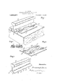
With the above objects in View, my invention consists .in certain novel details of the construction and arrangement of parts which will be hereinafter fully, clearly and concisely set forth in my specification, pointed out in my claims and illustrated in accompanying drawings in which- Figure 1 is a perspective view of my invention applied to a tie, a portion of the rail being broken away.
Fig. 2 is a perspective view of the tie plate, which I employ. in carrying out my invention. i
Fig. 3 is a perspective view of a portion of a rail which I also employ in carrying out my invention.
Fig. 4 is a diagrammatic sectional view of the corrugated flange illustrating the unequal density thereof.
Referring to the drawings, 5 indicates my improved rail which is of the ordinary construction, except the base. The rail base consists of the base flanges 6 and 7 the base flange 6 being of the ordinary construction and provided throughout its length with a straight edge, whereas the base flange 7 is corrugated or is provided with a corrugated edge 8. The corrugated edge 8 is formed on the flange by being rolled while the rail is hot enough to be susceptible of having the valleys or grooves '9 compressed. The corrugated edge is formed on the flange by passing the rail while hot, through corrugated rollers so arranged as to compress the Specification of Letters Patent.
Patented Sept. 18, 1917.
Serial No. 134,997.
metal at regular distances apart to form the valleys or grooves 9.
By forming the corrugated edge 8 by the rolling operation, no metal of the base flange is'removed and the flange is not weakened and the rail possesses its original weight and strength, although the base is of irregular width, being narrow at the depressions or valleys 9 and being widest, or the original width of the base flange, at the crests or ridges 10, the difference in widths being about one-eighth of an inch.
As above stated, the corrugated edge is rolled or pressed on to the base flange 7 without removing any metal of the flange, or .without any vertical displacement of metal on the bottom or top surface of the flange. By compressing the flange by means of corrugated rollers while the flange is hot, and in producing no displacement on the top or bottom surface of the flange, I produce a rail flange of an unequal or irregular density, the greatest density being at the valleys or grooves 9, and the least density at the crest or ridge of the corrugation, the maximum density being at points where the rail base is the narrowest.
My improved rail when completed, may therefore, be characterized as one having a base of irregular or different widths and having a flange whose edge is of unequal density. I
11 indicates my improved tie plate, which I employ in carrying out my invention which is rolled or pressed and is provided with a rail-bearing seat 12, and rail-bearing shoulder or abutment 13, which has a straight inner surface and is provided with a guiding projection 14 which projects above the top edge of the shoulder.
15 indicates spike openings being adjacent the rail-bearing shoulder or abutment 13, but are set back from the inner face of the shoulder 1?) so as to leave portions 16 of the shoulder between the spike opening and the inner face of the shoulder. These portions 16 when the tie plate is in use, serve as a protection to the shank of the spike, thus preventing wear or what is commonly known as throat cutting of the spike. By positioning spike openings 15 as described, the inner surface of the shoulder 13 is left unbroken or uninterrupted, thus giving a maximum contact between the edge ofthe rail flange and the shoulder.
'jacent the rail-bearing seat 12 is a corrugated shoulder 17 adapted to snugly fit into the corru ated ed e 8 of the rail flan e; The
t) D b spike openings 15 adjacent this shoulder, are likewise set back from the corrugated face the shoulder, thus leaving portions 16 of the shoulder between the spike openings and the corrugated face of the shoulder, and are located at the thickest point of the shoulder.
In Fig. 1 I have shown a spike in position, wherein it will be observed that the head 18 of the spike overlaps or breaks the joint between the flange and the corrugated face of the shoulder, the head of the spike when seated being on the top surface of the rail base flange. The corrugated shoulder 17- is likewise provided with a guiding projection 19, performing the same function as the pro j'ection 14c, and it wilrbe observed'that it has a rounded or curved inner surface, corresponding with the flange corrugations.
Having thus described my ii'iventionwhat I claim is:
1. In a rail anti-creeper, arail with op posite base flanges one of which is corrugated along its edge, the density of the metal of the base on lines transverse to the rail is preserved whereits transverse dimensions are diminished, and tie plates'on which the rail 1S confined. hav1ng opposite bearlng shoulders, one of each being corrugated to fit the corrugated edge of the rail;
2. A rail antl-creeper, comprising a ra1l having a rolled corrugated flange of unequal density, and a tie plate having a rolled corrugated shoulder, said tie plate being provided'with spike openings intersecting said corrugated shoulder and removed from the corrugated face thereof. H
3; A rail anti-creeper comprising a rail having a continuous straight edge flange throughout its length and a uniformly corrugated flange throughout its length, the said corrugated flange being formed by passing the rail through: a corrugated roller, thus compressing the material of the flange and not removing the same at certain distances apart, whereby the original weight and strength of the rail are preserved, and a rolled tie plate provided with a corrugated shoulder adapted to snugly fit the corrugations of the rail flange, said corrugated shoulder being provided. with a rigid upstanding guiding lug-for guiding the rail back to its original seat, should it become displaced by the loosening of the spikes.
4:. A rail anti-creeper comprising a rail provided with a straight flange. and a corrugated flange, the corrugations of the corrugated flange being formed by rollingandfla tie plate provided with a corrugated railbearing shoulder formed by rolling, and
with spike openings, the said spikeopenings passing through the shoulder and bodyof the plate and being removed from the corrugated face of the shoulder, thus leaving portions of the shoulder between the spikes and corrugated rail flange;
5. A rail anti-creeper comprising a rail havi'n'ga straight flange and a rolled corrugated flange of unequal density, a tieplate provided with 'a straight andi'a corrugated rail bearing shoulder. and with spike openings intersecting said shoulders, and a lug carried by each shoulder between the spike openings; l e g i In testimony whereof, I have -signed my name to this specification, in presence of. two subscribing. witnesses. x
BENJAMIN B. BETTS. lVitnesses:
Trros; H; GALBRAITI-I,
R. G. CRAIG.
Copies of this patent may be obtained for fiire cents each; by addressing the Commissioner of Patents; Washington, D. C.
Priority Applications (1)
| Application Number | Priority Date | Filing Date | Title |
|---|---|---|---|
| US13499716A US1240407A (en) | 1916-12-04 | 1916-12-04 | Combined anticreeping rail and tie-plate. |
Applications Claiming Priority (1)
| Application Number | Priority Date | Filing Date | Title |
|---|---|---|---|
| US13499716A US1240407A (en) | 1916-12-04 | 1916-12-04 | Combined anticreeping rail and tie-plate. |
Publications (1)
| Publication Number | Publication Date |
|---|---|
| US1240407A true US1240407A (en) | 1917-09-18 |
Family
ID=3308217
Family Applications (1)
| Application Number | Title | Priority Date | Filing Date |
|---|---|---|---|
| US13499716A Expired - Lifetime US1240407A (en) | 1916-12-04 | 1916-12-04 | Combined anticreeping rail and tie-plate. |
Country Status (1)
| Country | Link |
|---|---|
| US (1) | US1240407A (en) |
-
1916
- 1916-12-04 US US13499716A patent/US1240407A/en not_active Expired - Lifetime
Similar Documents
| Publication | Publication Date | Title |
|---|---|---|
| US1240407A (en) | Combined anticreeping rail and tie-plate. | |
| US603563A (en) | Gage-adjusting tie-plate | |
| US873707A (en) | Tie-plate. | |
| US557667A (en) | Tie-plate | |
| US776450A (en) | Railroad-track. | |
| US596731A (en) | Tie-plate | |
| US1018102A (en) | Railway-rail. | |
| US751201A (en) | Eenest f | |
| US1134455A (en) | Combination tie-plate and rail-fastener. | |
| US44455A (en) | Improvement in railroad-chairs | |
| US902446A (en) | Tie-plate. | |
| US427505A (en) | Railway-joint | |
| US814327A (en) | Railway-tie. | |
| US691037A (en) | Rail-joint. | |
| US720358A (en) | Rail-joint. | |
| US394679A (en) | Thomas a | |
| US1187925A (en) | Tie-plate. | |
| US684106A (en) | Metallic railroad-tie. | |
| US504981A (en) | Joint for railway-rails | |
| US958271A (en) | Tie-plate. | |
| US465260A (en) | Blank bar for tie-plates | |
| US808151A (en) | Railway-rail. | |
| US3044709A (en) | Rail anchor made of plate steel | |
| US949907A (en) | Tie-plate. | |
| US1318334A (en) | Tie-plate |