US1237668A - Pump, &c. - Google Patents
Pump, &c. Download PDFInfo
- Publication number
- US1237668A US1237668A US80092513A US1913800925A US1237668A US 1237668 A US1237668 A US 1237668A US 80092513 A US80092513 A US 80092513A US 1913800925 A US1913800925 A US 1913800925A US 1237668 A US1237668 A US 1237668A
- Authority
- US
- United States
- Prior art keywords
- drum
- pistons
- cylinder
- piston
- head
- Prior art date
- Legal status (The legal status is an assumption and is not a legal conclusion. Google has not performed a legal analysis and makes no representation as to the accuracy of the status listed.)
- Expired - Lifetime
Links
Images


Classifications
-
- F—MECHANICAL ENGINEERING; LIGHTING; HEATING; WEAPONS; BLASTING
- F04—POSITIVE - DISPLACEMENT MACHINES FOR LIQUIDS; PUMPS FOR LIQUIDS OR ELASTIC FLUIDS
- F04C—ROTARY-PISTON, OR OSCILLATING-PISTON, POSITIVE-DISPLACEMENT MACHINES FOR LIQUIDS; ROTARY-PISTON, OR OSCILLATING-PISTON, POSITIVE-DISPLACEMENT PUMPS
- F04C29/00—Component parts, details or accessories of pumps or pumping installations, not provided for in groups F04C18/00 - F04C28/00
- F04C29/02—Lubrication; Lubricant separation
Definitions
- WITN EssEs WWW of @wf F. W. MACHLET.
- This invention relates to engines, pumps, blowers, etc., of the kind illustrated in United States Letters Patent No. 902,501 granted to me October 27, 1908.
- a cylinder is revolved within a drum, the cylinder carrying pistons which work in and out thereof, and run in contact with the inner periphery of the drum; the cylinder being usually mounted eccentrically of the drum.
- the main object of myinvention is to provide a simple, inexpensive, practical durable and efficient device of this type.
- the pistons are arranged at intervals around the cylinder and mounted so that each piston may move in and out of the cylinder independently of the other pistons; and preferably the pressure of lubricating or other liquid contained in the cylinder itself is utilized against the inner ends of the several pistons, to force them outwardly so that their tips run in close contact with the inner periphery of the drum, thus avoiding leakage of air or other fluid past the pistons.
- the device is therefore espe cially serviceable as a blower, or as a moderate-pressure air-compressor, or as a vacuum pump; and the improvements may also be applied to steam and air-driven engines.
- the liquid within the piston-cylinder is fedfrom a separator arranged on the delivery side of the pump or blower, whereby said liquid is subjected to the pressure of the air or other fluid delivered from the pump; a communication being provided from said separator to the interior of the cylinder.
- Another feature of the invention resides in the structure or contour of the drum, and the relation thereto of the pistoncarrying cylinder.
- the interior contour of the drum is preferably elliptical; and the axis about which the cylinder revolves is about concentric with the curve of one side of the ellipse, for a considerable portion of said Specification of Letters Patent.
- Figure l is a sectional elevation of the pump or blower.
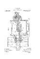
- Fig. 2 is a longitudinal sectional view of the same.
- Fig. 3 shows the pistons in a different position from Fig. 1, showing how a guidng tongue on one piston may cross the guiding tongue of another piston, in a certain how the delivery of air or liquid from the pump may be made uniform in volume or substantially so.
- Fig. 4 shows the pistons in still another position, showing a different crossing of the piston guidingtongues.
- Fig. 5 is a side elevation of the air compressor or blower including the separator, the latter beingshown partly in section.
- Fig. 6 is a perspective view of the cylinder which carries the pistons.
- the device seen at Fig. 6 is a single casting.
- Fig. 7 shows a modificationin which there is no relative movement between the pistons in each pair; it being therefore possible to make the pistons in each pair integral if desired.
- . position of the cylinder, and also illustrating Fig. 8 is a perspective diagram showing the cylinder turning in contact with the periphery of the drum at one portion thereof.
- the cylinder is mounted by means of gudgeons '9, 10, in bosses 11, 12, provided upon the side walls 6, 7 of drum 8.
- ball or roller bearings may be provided for said gudgeons, comprising for instance, grooved collars 13 on the gudgeons, and grooved rings 14 in the bosses, formingraceways for balls 15.
- From' gudgeon 9 may extend a drive-shaft 16 carrying drive pulley 17 and loose pulley 18.
- the contour of the inner periphery of drum 8 is preferably elliptical or nearly so.
- the pistons run idly, the latter being effective only when moving over the short portion 19 which extends between intake port 20 and delivery or outlet port 21.
- the axis of revolution of the piston-barrel or cylinder 5 may be substantially or almost concentric with this portion 19 of the drum periphery, to the end that each piston, when traversing said portion 19, may make little or no sliding movement in the cylinder 5, thus avoiding friction of the piston in ts guides when the pressure on one face of the piston is heavier than it is on the other side.
- the sliding movements of the piston in and out of the carrier 5 occur mainly when they are doing no work, so that they do not grind upon their guides or bearings, and hence are not liable to rapid wear.
- a passage 23 formed in the periphery 22 leads from port 20' up to the place where the cylinder 5 turns in contact with said periphery 22, whereby an open communication is preserved between the intake side of the pump and the chamber that forms above the descending piston, whereby the back pressure due to forming a vacuum above the descending piston is avoided, and the pressure on'one side of the piston balances that on the other side while the piston is sliding out of the cylinder.
- a similar passage 24 extends from 22, the partition between said passages being numbered 24.
- the passage 5 24 avoids undue-increase in pressure of air in the pocket formed above the rising piston above outlet 21 and insures like pressures on the upper and lower sides of the ascending pisto serving to lubricate the pistons and all the 1 moving parts of the pump, blower or engine.
- the cylinder 5 has radial mortises 26 to guide the pistons and these mortises are open at both thelr outer and inner ends, whereby the inner ends of the pistons are immersed in the fluid 25, or at least are pressed outwardly thereby against the inner periphery o the drum 8.
- thickness of the piston offers greater surface upon which the liquid 25 may press and hence the thickness of the piston may determine the pressure of its tip against the drum periphery, whereby leakage of air or other fluid past the piston may be reduced or prevented.
- the liquid that oozes out from the piston-guides and that is picked up by the tips of the pistons, may also serve to pack or seal the tips and side edges of the pistons, thus minimizing or preventing loss of efficiency by leakage past the pistons.
- Said piston cylinder 5 may, if desired, be fed with the liquid 25 from a receptacle 27 Fig. 5, in which receptacle it is subject to the pressure of the air or other fluid deliv- Increased ered by the pump or blower.
- the pressure to which the liquid in 27 is subjected is of course transmitted to the liquid 25 in the piston cylinder 5, with the results already mentioned.
- the liquid may be fed from 27 through a pipe 28 to the interior of boss 12 (Fig. 2) of the drum 8, filling the boss, and
- washer 29 may be placed upon drive-shaft 16 against the end of hub 11; and this washer may form one side of a drip receptacle 30 which catches such oil or liquid as pistons-may be packed or sealed. as already explained. It will hence be understood that there is a frequent or constant passage of oil U or liquid 25 out of the pump in the form of spray taken along with the air orfluid de- 115 oozes past washer 29, and delivers it to a 4 livered by the pump; and the mixture passes up through a pipe 33 lnto a separator 34:, at
- the pistons 1, 2 may be prolonged or formed with central guiding tongues 35, 36, which may pass between guiding tongues 37, 38 formed on the ends of pistons 3, 4. This increases the length of bearing of each piston, and tends to increase its steadiness and efficiency and reduce the friction and Wear.
- Fig. 1 it will be seen that the projecting portion of the lowermost piston is not greater than the portion which is confined in the guide-mortise in the cylinder 5; thus afford ing the piston ample support even at the time when it is doing maximum work; this support being due to the tongues aforesaid.
- the reason that the tongues of the pistons in one pair are arranged interstitially with the tongues in the other pair will be apparent from Figs. 3 and 1, in which it will be seen that in some positions of the cylinder, a tongue in one pair may cross a tongue in the other pair.
- This blower or pump is not only eflicient, but it also has the advantage of delivering fiuid with substantial uniformity or steadiness, as it will be understood from Fig. 3 that the intervals between succeeding deliveries by the pistons may be made very slight or eliminated, by making the portion 19 of the drum periphery of the proper length; and this feature renders the device very desirable for use in pumping liquids, where a smooth flow or delivery is needed.
- the invention is not limited to the particular means described for sealing and lubricating the moving parts, nor to the described means for subjecting the liquid 25 to pressure.
- the length 19 of the drum periphery along which the pistons are effective being much less thanthe portion of the periphery along which the pistons run idly, said portion 19 is arranged at the bottom of the structure, so that the ports 20 and 21 may be at the lower part of the casing. This arrangement facilitates the sweeping of the liquid 25 directly from the basin 32 over to the outlet port 21.
- the pistons in each pair may be made relatively immovable, and, if desired, in a single piece.
- the contour 39 of the inner periphery of the drum is different, but the effective lower portion 19 thereof (between the intake and outlet ports seen at the other figures, or between points A and B) is about concentric with the axis of revolution of the piston cylinder 5, so that there is little or no movement o'f the pistons when 'having inlet they are carrying loads. If the pistons in each pair are made in a single piece, the length of bearing or support will of course be very great, but the liquid in the cylinder 5 will no longer serve to press the piston tips out against the periphery ofthe drum.
- the pistons can be made as in the other figures, so that each piston can be moved radially independently of all the others, so that the pressure of the liquid 25 can be utilized to thrust out the pistons for the purpose mentioned.
- the contour of the drum is such that the tips of the pistons in, each pair are constantly in engagement with the periphery of the drum, even'though there is no relative movement between the pistons in each pair.
- Fig. 7 is like Fig. 9, except that the drum is nearly cylindrical, and consequently there is more sliding movement of the pistons when under pressure or when doing work.
- Each pair of pistons could be made in a single piece, and the opposite tips would keep in contact with the periphery of the drum as the cylinder revolves.
- the hubs 40 of the piston-cylinder 5 are radially recessed at 41, to afford a clearance for the tool used in cutting or finishing the guide-slots 4:2 in which the pistons work;
- a pump of the character described the combination with a drum, a cylinder therein and a piston mounted in the cylinder to move in and out thereof, of means extending to the delivery side of the pump to utilize pressure of air or fluid delivered by the device for constantly forcing said piston against the wall of the drum, said means including means to subject the fluid to constant ressure.
Description
F. W. MACHLET.
PUMP, 6L0.
APPLICATION FILED NOV- !4. I913- INVENTOR:
Patented Aug. 21, 1917.
5 SHEETSSHEET 1.
WITN EssEs; WWW of @wf F. W. MACHLET.
PUMP, &c.
APPLICATION FILED NOV. 14. \913.
1 37,668. Patented Aug. 21, 1917.
5 SHEETS-SHEET 3.
FIG. 3.
WITNESSES:
F. W. MACHLET.
PUMP, &c.
APPLICATION FILED NOV. 14. 1913. 1,237,668. Patented Aug. 21,1917.
5 SHEETSSHEET 4.
wmuzs F. W. MACHLET.
PUMP, &c-
APPLICATION FILED NOV-14; I913.
Patented Aug. 21, 1917 5 SHEETS-SHEET 5.
INVENTOR: WW
ATTORN Y' WITNESSES:
FRITZ W. MACHLET, OF ELIZABETH, NEW JERSEY.
PUMP, &c.
To all whom it may concern:
Be it known that I, FRITZ W. MAOHLET, a citizen of the United States, residing in Elizabeth, in the county of Union and State of New Jersey, have invented certain new and useful Improvements in Pumps, &c., of which the following is a specification.
This invention relates to engines, pumps, blowers, etc., of the kind illustrated in United States Letters Patent No. 902,501 granted to me October 27, 1908. In this type, a cylinder is revolved within a drum, the cylinder carrying pistons which work in and out thereof, and run in contact with the inner periphery of the drum; the cylinder being usually mounted eccentrically of the drum.
The main object of myinvention is to provide a simple, inexpensive, practical durable and efficient device of this type.
' In the preferred form of the present in vention, the pistons are arranged at intervals around the cylinder and mounted so that each piston may move in and out of the cylinder independently of the other pistons; and preferably the pressure of lubricating or other liquid contained in the cylinder itself is utilized against the inner ends of the several pistons, to force them outwardly so that their tips run in close contact with the inner periphery of the drum, thus avoiding leakage of air or other fluid past the pistons. The device is therefore espe cially serviceable as a blower, or as a moderate-pressure air-compressor, or as a vacuum pump; and the improvements may also be applied to steam and air-driven engines.
The liquid within the piston-cylinder is fedfrom a separator arranged on the delivery side of the pump or blower, whereby said liquid is subjected to the pressure of the air or other fluid delivered from the pump; a communication being provided from said separator to the interior of the cylinder.
Another feature of the invention resides in the structure or contour of the drum, and the relation thereto of the pistoncarrying cylinder. The interior contour of the drum is preferably elliptical; and the axis about which the cylinder revolves is about concentric with the curve of one side of the ellipse, for a considerable portion of said Specification of Letters Patent.
side. The work of the piston is done when it is traveling along the side of the ellipse, between the intake and delivery ports of the drum; and hence while the piston is under pressure, or doing work, there is little or no movement of the piston into or out of the drum, and friction, wear and loss of power are consequently avoided. This construction is favored by making each piston separate from all the others; and in order to give each an ample bearing, it is provided with tongues projecting in toward the axis of the cylinder, which is hollow.
Other features and advantages will hereinafter appear.
In the accompanying drawings,
Figure l is a sectional elevation of the pump or blower.
Fig. 2 is a longitudinal sectional view of the same.
Patented Aug. 21, 31917.
Application filed November 14, 1913. Serial No. 800,925.
Fig. 3 shows the pistons in a different position from Fig. 1, showing how a guidng tongue on one piston may cross the guiding tongue of another piston, in a certain how the delivery of air or liquid from the pump may be made uniform in volume or substantially so.
Fig. 4 shows the pistons in still another position, showing a different crossing of the piston guidingtongues.
Fig. 5 is a side elevation of the air compressor or blower including the separator, the latter beingshown partly in section.
Fig. 6 is a perspective view of the cylinder which carries the pistons. The device seen at Fig. 6 is a single casting.
Fig. 7 shows a modificationin which there is no relative movement between the pistons in each pair; it being therefore possible to make the pistons in each pair integral if desired.
. position of the cylinder, and also illustrating Fig. 8 is a perspective diagram showing the cylinder turning in contact with the periphery of the drum at one portion thereof. The cylinder is mounted by means of gudgeons '9, 10, in bosses 11, 12, provided upon the side walls 6, 7 of drum 8. If desired, ball or roller bearings may be provided for said gudgeons, comprising for instance, grooved collars 13 on the gudgeons, and grooved rings 14 in the bosses, formingraceways for balls 15. From' gudgeon 9 may extend a drive-shaft 16 carrying drive pulley 17 and loose pulley 18.
The contour of the inner periphery of drum 8 is preferably elliptical or nearly so. Along the larger portion of this periphery the pistons run idly, the latter being effective only when moving over the short portion 19 which extends between intake port 20 and delivery or outlet port 21. The axis of revolution of the piston-barrel or cylinder 5 may be substantially or almost concentric with this portion 19 of the drum periphery, to the end that each piston, when traversing said portion 19, may make little or no sliding movement in the cylinder 5, thus avoiding friction of the piston in ts guides when the pressure on one face of the piston is heavier than it is on the other side. In other Words, the sliding movements of the piston in and out of the carrier 5 occur mainly when they are doing no work, so that they do not grind upon their guides or bearings, and hence are not liable to rapid wear. In
fact, the wear is so slight, that in many cases wooden pistons may be employed, which are not only inexpensive, but are also desirable because of their lightness, conducing to silence of operation and long life of the inner periphery 19, 22 of the drum. Very satisfactory pistons may be made from a good grade of maple; and the same may be impregnated with parafiin.
A passage 23 formed in the periphery 22 leads from port 20' up to the place where the cylinder 5 turns in contact with said periphery 22, whereby an open communication is preserved between the intake side of the pump and the chamber that forms above the descending piston, whereby the back pressure due to forming a vacuum above the descending piston is avoided, and the pressure on'one side of the piston balances that on the other side while the piston is sliding out of the cylinder. A similar passage 24 extends from 22, the partition between said passages being numbered 24. The passage 5 24 avoids undue-increase in pressure of air in the pocket formed above the rising piston above outlet 21 and insures like pressures on the upper and lower sides of the ascending pisto serving to lubricate the pistons and all the 1 moving parts of the pump, blower or engine.
The cylinder 5 has radial mortises 26 to guide the pistons and these mortises are open at both thelr outer and inner ends, whereby the inner ends of the pistons are immersed in the fluid 25, or at least are pressed outwardly thereby against the inner periphery o the drum 8. thickness of the piston offers greater surface upon which the liquid 25 may press and hence the thickness of the piston may determine the pressure of its tip against the drum periphery, whereby leakage of air or other fluid past the piston may be reduced or prevented. The liquid that oozes out from the piston-guides and that is picked up by the tips of the pistons, may also serve to pack or seal the tips and side edges of the pistons, thus minimizing or preventing loss of efficiency by leakage past the pistons.
Said piston cylinder 5 may, if desired, be fed with the liquid 25 from a receptacle 27 Fig. 5, in which receptacle it is subject to the pressure of the air or other fluid deliv- Increased ered by the pump or blower. The pressure to which the liquid in 27 is subiected, is of course transmitted to the liquid 25 in the piston cylinder 5, with the results already mentioned. The liquid may be fed from 27 through a pipe 28 to the interior of boss 12 (Fig. 2) of the drum 8, filling the boss, and
passing through the open end of the cylinder 5 into its interior, and also passing through the open opposite end of the cylin-- der to fill the-boss 11. Both sets of ball bearings mav thus be lubricated.
To prevent loss of fluid or pressure, a-
the bottom of which is the receptacle 27 into which the separated liquid falls, to be again circulated through the pump under the pressure of the compressed air delivered by the pump.
The pistons 1, 2 may be prolonged or formed with central guiding tongues 35, 36, which may pass between guiding tongues 37, 38 formed on the ends of pistons 3, 4. This increases the length of bearing of each piston, and tends to increase its steadiness and efficiency and reduce the friction and Wear. At Fig. 1 it will be seen that the projecting portion of the lowermost piston is not greater than the portion which is confined in the guide-mortise in the cylinder 5; thus afford ing the piston ample support even at the time when it is doing maximum work; this support being due to the tongues aforesaid. The reason that the tongues of the pistons in one pair are arranged interstitially with the tongues in the other pair will be apparent from Figs. 3 and 1, in which it will be seen that in some positions of the cylinder, a tongue in one pair may cross a tongue in the other pair.
This blower or pump is not only eflicient, but it also has the advantage of delivering fiuid with substantial uniformity or steadiness, as it will be understood from Fig. 3 that the intervals between succeeding deliveries by the pistons may be made very slight or eliminated, by making the portion 19 of the drum periphery of the proper length; and this feature renders the device very desirable for use in pumping liquids, where a smooth flow or delivery is needed. The invention is not limited to the particular means described for sealing and lubricating the moving parts, nor to the described means for subjecting the liquid 25 to pressure.
The length 19 of the drum periphery along which the pistons are effective, being much less thanthe portion of the periphery along which the pistons run idly, said portion 19 is arranged at the bottom of the structure, so that the ports 20 and 21 may be at the lower part of the casing. This arrangement facilitates the sweeping of the liquid 25 directly from the basin 32 over to the outlet port 21.
By the diagram .at Fig. 9, it is shown how the pistons in each pair may be made relatively immovable, and, if desired, in a single piece. In this view, the contour 39 of the inner periphery of the drum is different, but the effective lower portion 19 thereof (between the intake and outlet ports seen at the other figures, or between points A and B) is about concentric with the axis of revolution of the piston cylinder 5, so that there is little or no movement o'f the pistons when 'having inlet they are carrying loads. If the pistons in each pair are made in a single piece, the length of bearing or support will of course be very great, but the liquid in the cylinder 5 will no longer serve to press the piston tips out against the periphery ofthe drum. It is obvious that if desired, the pistons can be made as in the other figures, so that each piston can be moved radially independently of all the others, so that the pressure of the liquid 25 can be utilized to thrust out the pistons for the purpose mentioned. In Fig. 9, the contour of the drum is such that the tips of the pistons in, each pair are constantly in engagement with the periphery of the drum, even'though there is no relative movement between the pistons in each pair.
The diagram at Fig. 7 is like Fig. 9, except that the drum is nearly cylindrical, and consequently there is more sliding movement of the pistons when under pressure or when doing work. Each pair of pistons could be made in a single piece, and the opposite tips would keep in contact with the periphery of the drum as the cylinder revolves.
As seen clearly at Fig. 6, the hubs 40 of the piston-cylinder 5 are radially recessed at 41, to afford a clearance for the tool used in cutting or finishing the guide-slots 4:2 in which the pistons work;
Other variations may be resorted to within the scope of my invention, and portions of the improvements may be used without others.
Having thus described my invention, 1 claim:
1. The combination of a drum approxi mately elliptical in cross section, said drum having inlet and outlet ports both upon one side of the ellipse, a revoluble head journaled in said drum at a point substantially concentric with that portion of said side of the ellipse which extends between said ports, independently movable pistons mounted on said head and constantly in engagement with the inner periphery of the drum, to enablesaid periphery to control the movements of the pistons relatively to said head; whereby the movement of each piston relatively to said head is minimized or eliminated while the piston is under pressure in traveling between said ports, and means to urge the pistons outwardly. v
2. The combination of a drum approximately elliptical in cross section, said drum and outlet ports both upon one side of the ellipse, a revoluble head journaled in said drum at a point substantially concentric with that portlon of said side of the ellipse which extends between said ports,
two pairs of separate pistons mounted on said head and each piston movable independently of all the others to runupon the walls of the drum; said pistons disposed at naled in said drum at at equal intervals upon said head, and means dependent upon the revolution of said head for forcing the pistons outwardly.
3. The combination of a drum substantially elliptical in cross section, said drum having inlet and outlet ports both upon one side of the ellipse, a revoluble head jouroint substantially concentric with that portion of said side of the ellipse which extends between said ports,
two pans of separate pistons mounted on said head and each movable independently of all the others to run upon the walls of the drum, said pistons disposed at equal intervals upon said head, said pistons mounted to slide in said head, and means being proyided to, supply a lubricating liquid under pressure to said pistons at their inner ends, to force them outwardly against the periphery of the drum.
4. The combination of a drum substantially elliptical in cross section, said drum having inlet and outlet ports both upon one side of the ellipse, a revoluble head journaled in said drum at a point substantially concentric with that portion of said side of the ellipse which extends between saidports, two pairs of separate pistons mounted on said head and each movable independently of all'the others to run upon the walls of the drum, said pistons disposed at equal intervals upon sald head, said pistons mounted to slide in said head, and means being provided to supply a lubricating liquid 'under pressure to said pistons at their inner ends, to force them outwardly against the periphery of the drum; said pistonsrecessed at their inner edges to form guiding tongues, the tongues of the pistons in one pair arranged to move in the recesses of the 7 other pair as the head revolves.
5. The combination with a drum, a revolving head therein, and a movable piston carried by said head, of a separator on the delivery side of the drum, and means dependent upon the, revolution of said head to conduct the separated liquid from the separator to the drum under pressure to press said piston outwardly into contact with the wall of the drum. i
6. The combination with a drum and a revolving head therein, said head being a receptacle for liquid, of a piston carried by said head and communicating with said chamber to be forced outwardly by the pressure of the liquid, a separator on the delivery side of the drum, and means to conduct the separated liquid backto said receptacle, where it is under the pressure of the air'or gas delivered by the pump or device, wherej by the piston is forced outwardly into contact with the wall of the drum.
7. The combination of a drum, a head memes journaled therein eccentrically thereof, movable pistons projecting from said head, said head provided with means for containing a lubricating liquid in position to act outwardly against said pistons, and means for subjecting said lubricating liquid to a constant pressure tending to cause it to force said pistons outwardly against the surface of the drum.
8. The combination of a drum, a head journaled therein eccentrically thereof, sliding pistons mounted in said head and movable independently of one another, said head provided with means for containing lubrirevoluble hollow head j ournaled therein eccentrically thereof to contain a lubricating liquid, movable pistons projecting from said head to extend to the wall of the drum and in communication with the lubricating liquid to be pressed outwardly thereby, and means for subjecting saidlubricating liquid to constant pressure, tosupply it to the interior of said drum and constantly tend to force said pistons outwardly.
10. The combination of a drum, a revoluble head j ournaled therein eccentrically thereof, two pairs of sliding pistons projecting from said head to engage the wall of the drum, and means exterior to said head for subjecting lubricating liquid within said head to constant pressure, to tend constantly to'press all of said pistons outwardly.
11. The combination of a drum, a revoluthem outwardly against the inner periphery 4 of the drum. 1
12. The combination witha drum containing a receptacle and a revolving member mounted within the drum eccentrically of the latter, of sliding pistons mounted in said revolving member and penetrating into said receptacle, and means exterior to said receptacle but connected thereto, for subjecting lubricating liquid to constant pressure into said receptacle to force the pistons constantly outwardly.
13. The combination with a drum and a revolving member mounted within the drum eccentrically of the latter, of slidin pistons mounted in said revolving mem er and penetrating into said receptacle, whereby they may be forced outwardly by the pressure of lubricating liquid in said receptacle, a separator in communication with the delivery side of said drum, and means to conduct the Separated liquid from the separator back to said receptacle, to subject the liquid in said receptacle to the pressure of the air or fluid delivered by the drum or" engine.
14. The combination with a cylinder having pistons and a drum within which the cylinder revolves, the pistons being movable into and out of the cylinder, of means for utilizing liquid within the cylinder to press the pistons outwardly constantly against the drum, said means including means for subjecting the liquid to constant pressure.
15. The combination with a drum and a cylinder. mounted therein to run in contact therewith, of a piston carried by said cylinder to move in and out thereof, and means to utilize liquid to press the edge of said piston constantly against the drum, said means ineluding means for subjecting the liquid to constant pressure.
16. In an air or fluid compressor or blower, the combination with a drum, a cylinder mounted to revolve therein, and a piston mounted to move in and out of the cylinder and to bear upon the periphery of the drum, of a separator arranged on the delivery side of the compressor or blower, and a communication between said separator and said piston to cause the separated liquid to flow back from the separator to the piston to force the latter against the wall of the drum.
17. In a pump of the character described, the combination with a drum, a cylinder therein and a piston mounted in the cylinder to move in and out thereof, of means extending to the delivery side of the pump to utilize pressure of air or fluid delivered by the device for constantly forcing said piston against the wall of the drum, said means including means to subject the fluid to constant ressure.
18. n a device of the character described,
the combination with a drum and a cylinder mounted therein to run in contact with the wall thereof, of pistons independently slidable in and out of said cylinder, and means to utilize the fluid delivered by said device to force the pistons constantly into contact with the wall of the drum, said means including means to subject the fluid to constant pressure.
19. In an air compressor or blower, the combination with a drum and a. cylinder therein, of pistons independently slidable in and out of said cylinder, a liquid contained within said cylinder, and means to utilize the pressure of air delivered by the device for subjecting said liquid to pressure, to lubricate the pistons and cylinder, and also force the pistons against the wall of the drum.
20. In an air compressor or blower, the
-combination with a drum and a cylinder therein, of pistons independently slidable in and out of said cylinder, a liquld contained within said cylinder, and means to utilize the pressure of air delivered by the device for subjecting said liquid to pressure, to lubricate the pistons and cylinder, and also force the pistons against the wall of the drum, and seal and lubricate said pistons.
21. In an air compressor or blower, the
combination with a drum and a cylinder with the delivered air from said compressor or blower is collected and returned to be used again. v
22. The combination of an approximately elliptical drum, a cylinder mounted therein about concentrically with the curve of one side of the ellipse for a considerable portion of saidside, said drum being provided with inlet and outlet ports between which said portion extends, pistons mounted independently of one another in said cylinder, and
means to hold said pistons yieldingly in engagement with the periphery of the drum during therevolution of the cylinder.
23. The combination of an approximately elliptical drum, a cylinder mounted therein about concentrically with the curve of one side of the ellipse for a considerable portion of said side, said drum being provided with inlet and outlet ports between which said portion extends, pistons mounted independently of one another in said cylinder, and means to hold said pistons yieldingly in engagement with the periphery of the drum during the revolution of the cylinder; the piston provided with tongues projecting in toward the axis of the cylinder, and said cylinder having inwardly directed rigid guides for said tongues.
24. The combination with a drum and a revolving head therein, of pistons carried by said head, said head being a hollow recep tacle for liquid, and said pistons working in ways that open directly into the hollow of the receptacle, said liquid being under pressure, and means to subject the liquid to pressure to force the piston edges hydraulr callyagainst the inner wall of the drum.
25. The combination with a drum and a revolving head therein, of pistons carried by said head, said head having a hollow body to serve as a receptacle for liquid under pressure, and said pistons entering the hollow liquid-containing body of said re ceptacle, and means dependent upon the revolution of said head for subjecting the I liquid in said head to pressure, to cause the pistons to be forced outwardly hydrauli- 1o FRITZ w. MAOHLET.
Witnesses:
SAMUEL R. OGDEN, Anonrn Mnemr.
Priority Applications (1)
| Application Number | Priority Date | Filing Date | Title |
|---|---|---|---|
| US80092513A US1237668A (en) | 1913-11-14 | 1913-11-14 | Pump, &c. |
Applications Claiming Priority (1)
| Application Number | Priority Date | Filing Date | Title |
|---|---|---|---|
| US80092513A US1237668A (en) | 1913-11-14 | 1913-11-14 | Pump, &c. |
Publications (1)
| Publication Number | Publication Date |
|---|---|
| US1237668A true US1237668A (en) | 1917-08-21 |
Family
ID=3305486
Family Applications (1)
| Application Number | Title | Priority Date | Filing Date |
|---|---|---|---|
| US80092513A Expired - Lifetime US1237668A (en) | 1913-11-14 | 1913-11-14 | Pump, &c. |
Country Status (1)
| Country | Link |
|---|---|
| US (1) | US1237668A (en) |
Cited By (11)
| Publication number | Priority date | Publication date | Assignee | Title |
|---|---|---|---|---|
| US2541405A (en) * | 1946-12-18 | 1951-02-13 | Bowser Inc | Rotary hand pump |
| DE917744C (en) * | 1951-04-28 | 1954-09-09 | Leybold S Nachfolger E | Two-stage rotating oil pump with nested pump rooms |
| US2759664A (en) * | 1949-05-07 | 1956-08-21 | Alois Vogt Dr | Two-stage pump, in particular a vacuum pump |
| US2820417A (en) * | 1954-05-10 | 1958-01-21 | American Brake Shoe Co | Fluid pressure energy translating device |
| US2892584A (en) * | 1955-06-27 | 1959-06-30 | Emanuel S Briscoe | Vane-type rotary pumps |
| US2949081A (en) * | 1956-04-25 | 1960-08-16 | Hydro Aire Inc | Pumping cavity for rotary vane pump |
| US3071079A (en) * | 1958-12-12 | 1963-01-01 | Clark Equipment Co | Single vane pump |
| DE1172397B (en) * | 1959-03-17 | 1964-06-18 | Erwin Lothar Holland Merten | Rotary piston vacuum pump |
| US3193190A (en) * | 1965-07-06 | Lindberg vacuum pump | ||
| US3199771A (en) * | 1961-10-19 | 1965-08-10 | Becker G M B H Geb | Multicell machine operating as a combination pressure-vacuum generator |
| US4795325A (en) * | 1981-10-30 | 1989-01-03 | Hitachi, Ltd. | Compressor of rotary vane type |
-
1913
- 1913-11-14 US US80092513A patent/US1237668A/en not_active Expired - Lifetime
Cited By (11)
| Publication number | Priority date | Publication date | Assignee | Title |
|---|---|---|---|---|
| US3193190A (en) * | 1965-07-06 | Lindberg vacuum pump | ||
| US2541405A (en) * | 1946-12-18 | 1951-02-13 | Bowser Inc | Rotary hand pump |
| US2759664A (en) * | 1949-05-07 | 1956-08-21 | Alois Vogt Dr | Two-stage pump, in particular a vacuum pump |
| DE917744C (en) * | 1951-04-28 | 1954-09-09 | Leybold S Nachfolger E | Two-stage rotating oil pump with nested pump rooms |
| US2820417A (en) * | 1954-05-10 | 1958-01-21 | American Brake Shoe Co | Fluid pressure energy translating device |
| US2892584A (en) * | 1955-06-27 | 1959-06-30 | Emanuel S Briscoe | Vane-type rotary pumps |
| US2949081A (en) * | 1956-04-25 | 1960-08-16 | Hydro Aire Inc | Pumping cavity for rotary vane pump |
| US3071079A (en) * | 1958-12-12 | 1963-01-01 | Clark Equipment Co | Single vane pump |
| DE1172397B (en) * | 1959-03-17 | 1964-06-18 | Erwin Lothar Holland Merten | Rotary piston vacuum pump |
| US3199771A (en) * | 1961-10-19 | 1965-08-10 | Becker G M B H Geb | Multicell machine operating as a combination pressure-vacuum generator |
| US4795325A (en) * | 1981-10-30 | 1989-01-03 | Hitachi, Ltd. | Compressor of rotary vane type |
Similar Documents
| Publication | Publication Date | Title |
|---|---|---|
| US1237668A (en) | Pump, &c. | |
| US1749121A (en) | Rotary pump | |
| US1743977A (en) | Rotary engine | |
| US1834976A (en) | Rotary compressor, pump or the like | |
| US4104010A (en) | Rotary compressor comprising improved rotor lubrication system | |
| US3521981A (en) | Pump or compressor | |
| US848446A (en) | Lubricating system. | |
| US1119972A (en) | Engine, air-pump, &c. | |
| CN208996942U (en) | Scroll compressor having a plurality of scroll members | |
| US2846138A (en) | Refrigeration compressor | |
| DE2402029B2 (en) | Lubricating device for rotary piston compressors | |
| US2246273A (en) | Rotary pump | |
| US5618165A (en) | Variable displacement and constant pressure pump | |
| US1676783A (en) | Rotary pump | |
| US4392797A (en) | Device for lubricating a rotary piston air pump | |
| JPH0584399B2 (en) | ||
| US2785851A (en) | Pump and/or rotative compressor with prismatic pistons | |
| US2417183A (en) | Variable stroke radial cylinder type pump | |
| KR950033103A (en) | Rotary compressor | |
| US2233017A (en) | Compressor | |
| US2843312A (en) | Compressor | |
| US1946344A (en) | Lubrication system | |
| US2049794A (en) | Pump | |
| US1936614A (en) | Pressure pump | |
| US3241747A (en) | Oil pump and oil system for air compressor |