US1237479A - Brake-shoe. - Google Patents
Brake-shoe. Download PDFInfo
- Publication number
- US1237479A US1237479A US17825417A US17825417A US1237479A US 1237479 A US1237479 A US 1237479A US 17825417 A US17825417 A US 17825417A US 17825417 A US17825417 A US 17825417A US 1237479 A US1237479 A US 1237479A
- Authority
- US
- United States
- Prior art keywords
- lug
- shoe
- brake
- metal
- integral
- Prior art date
- Legal status (The legal status is an assumption and is not a legal conclusion. Google has not performed a legal analysis and makes no representation as to the accuracy of the status listed.)
- Expired - Lifetime
Links
Images
Classifications
-
- F—MECHANICAL ENGINEERING; LIGHTING; HEATING; WEAPONS; BLASTING
- F16—ENGINEERING ELEMENTS AND UNITS; GENERAL MEASURES FOR PRODUCING AND MAINTAINING EFFECTIVE FUNCTIONING OF MACHINES OR INSTALLATIONS; THERMAL INSULATION IN GENERAL
- F16D—COUPLINGS FOR TRANSMITTING ROTATION; CLUTCHES; BRAKES
- F16D65/00—Parts or details
- F16D65/02—Braking members; Mounting thereof
- F16D65/04—Bands, shoes or pads; Pivots or supporting members therefor
- F16D65/06—Bands, shoes or pads; Pivots or supporting members therefor for externally-engaging brakes
- F16D65/062—Bands, shoes or pads; Pivots or supporting members therefor for externally-engaging brakes engaging the tread of a railway wheel
Definitions
- the object of the invention is the provision of an improved brake shoe consisting mainly of'cast metal and having a reinforced back of steel or wrought metal and a perforated lug formed in part of the reinforcing back and separately fashioned metallic elements interlocking therewith, the back and lug being securely and firmly attached to the cast metal portion thereof.
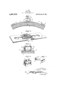
- Figure 1 is a longitudinal, central vertical section in elevation of the complete shoe.
- Fig. 2 is a perspective view of the reinforcing back with the integral bent up portions of the metal which form parts of the lug to receive the key.
- Fig. 3 is a cross section of the complete shoe on line X-X of Fig. 1 illustrating the interlocking parts-of the lug.
- Fig. 4 is a perspective view portion of the lug detached.
- Fig. 5 is a perspective view of one of the two locking clamps which unite the top portion of the lug shown by Fig. 4, to the parts of the lug integral with the reinforcing back.
- the letter A designates the reinforcing back of wrought metal or steel having parts of the metal removed to form the holes 13, B, and the opposite side edges cut at C, C, and the metal bent up perpendicularly to the plane of the back and the extreme edges bent to lie in planes parallel with the surface of the back, desig of the top nated by D, D, constituting part of the complete key lug E, as shown.
- the top of the lug F consists of a strip of metal G, of proper dimensions having the ends bent over as shown by Fig. 4 so the ends II will match and frictionally engage the top surfaces of the hook portions of the lower parts of the lug integral with the back.
- each clamp I having a slot J within which frictionally fits one turned over end of the lower part of the lug and one end H of the upper part of the lug.
- the extreme ends K, K, of each clamp are then bent outwardly and around against the exterior surfaces of the upper and lower parts of the lug as shown by Figs. 1 and 3, thus securely anchoring the top part of the lug to the lower parts which are integral with the back.
- the body or wearing part of the shoe L consists of metal cast around the reinforcing back which is bent to a curved shape, the cast metal overlapping the ends of the back at M, M, filling the holes 13, B and the recesses N, N adjacent to the key lug, thus securing the back rigidly and firmly to the body of the shoe.
- a shoe is thus provided with a strong key lug securely attached to the body of the shoe.
- the back of the shoe is reinforced, and the shoe as a whole constitutes a superior article, relatively cheap in first cost, easy to manufacture and efficient in operation for the purpose intended.
- a brake shoe having a cast metal body and a reinforcing back with a key lug; the lug being formed of integral portions of the back turned upwardly, a separate top portion matching the parts integral-with the back, and locking clamps.
- a brake shoe having a castmetal body, andv a reinforcing back with a key lug; the lug being formed of integral side portions of the back turned up and each having a hook shaped end, a top part having hook shaped ends, and two locking clamps, each clamp having a slot within which adjacent hooked shaped ends at one side are located and the ends of the clamp bent outwardly lower part of the lug and. around the said top part and the said integral upturned portion of the back.
- a brake shoe having a cast metal body and a reinforcing back With a key lug; the
Description
J. COOK.
BRAKE SHOE.
APPLICATION FILED JULY 2, 19!].
Patented Aug. 21, 1917.
//7 ref/for JUDSON cook, or ALBANY, 1\TEW YORK.
BRAKE-SHOE. 7
Specification. of Letters Patent.
Patented Aug. 21, 1917.
Application filed. July 2,1917. Serial No. 178,254.
To all whom it may concern:
Be it known that I, JUDsoN 0001:, a citizen of the United States, residing at Albany, in the county of Albany and State of New York, have invented certain new and useful Improvements in Brake-Shoes; and I do hereby declare the following to be a full, clear, and exact description of the invention, such as will enable others skilled in the art to which it appertains to make and use the same.
The object of the invention is the provision of an improved brake shoe consisting mainly of'cast metal and having a reinforced back of steel or wrought metal and a perforated lug formed in part of the reinforcing back and separately fashioned metallic elements interlocking therewith, the back and lug being securely and firmly attached to the cast metal portion thereof.
With this end in view the invention consists in certain novelties of construction and combination of parts as hereinafter set forth and claimed.
The acompanying drawing illustrates an example of the embodiment of the invention, the parts being fashioned and combined according to the best mode of procedure I have so far devised for the purpose.
Referring to the drawing,
Figure 1 is a longitudinal, central vertical section in elevation of the complete shoe.
Fig. 2 is a perspective view of the reinforcing back with the integral bent up portions of the metal which form parts of the lug to receive the key.
Fig. 3 is a cross section of the complete shoe on line X-X of Fig. 1 illustrating the interlocking parts-of the lug.
Fig. 4 is a perspective view portion of the lug detached.
Fig. 5 is a perspective view of one of the two locking clamps which unite the top portion of the lug shown by Fig. 4, to the parts of the lug integral with the reinforcing back.
In the said drawing, the letter A designates the reinforcing back of wrought metal or steel having parts of the metal removed to form the holes 13, B, and the opposite side edges cut at C, C, and the metal bent up perpendicularly to the plane of the back and the extreme edges bent to lie in planes parallel with the surface of the back, desig of the top nated by D, D, constituting part of the complete key lug E, as shown.
The top of the lug F, consists of a strip of metal G, of proper dimensions having the ends bent over as shown by Fig. 4 so the ends II will match and frictionally engage the top surfaces of the hook portions of the lower parts of the lug integral with the back.
To secure the top part of the lug to the lower part, two locking clamps I, I, shown in Fig. 5, are employed. Each clamp I having a slot J within which frictionally fits one turned over end of the lower part of the lug and one end H of the upper part of the lug. The extreme ends K, K, of each clamp are then bent outwardly and around against the exterior surfaces of the upper and lower parts of the lug as shown by Figs. 1 and 3, thus securely anchoring the top part of the lug to the lower parts which are integral with the back.
The body or wearing part of the shoe L consists of metal cast around the reinforcing back which is bent to a curved shape, the cast metal overlapping the ends of the back at M, M, filling the holes 13, B and the recesses N, N adjacent to the key lug, thus securing the back rigidly and firmly to the body of the shoe. A shoe is thus provided with a strong key lug securely attached to the body of the shoe. The back of the shoe is reinforced, and the shoe as a whole constitutes a superior article, relatively cheap in first cost, easy to manufacture and efficient in operation for the purpose intended.
Having thus described my invention, what I claim as new and desire to secure by Letters Patent, is:
1. A brake shoe having a cast metal body and a reinforcing back with a key lug; the lug being formed of integral portions of the back turned upwardly, a separate top portion matching the parts integral-with the back, and locking clamps.
2. A brake shoe having a castmetal body, andv a reinforcing back with a key lug; the lug being formed of integral side portions of the back turned up and each having a hook shaped end, a top part having hook shaped ends, and two locking clamps, each clamp having a slot within which adjacent hooked shaped ends at one side are located and the ends of the clamp bent outwardly lower part of the lug and. around the said top part and the said integral upturned portion of the back.
3. A brake shoe having a cast metal body and a reinforcing back With a key lug; the
being formed of integral-portions of the back by cutting the metal on line C-C and turning up' the terlocking clamps.
ture.
JUDSON COOK.
' Copies of this patent may be obtained for five cents" each, by addressing the Gommissioner of fatnt s, Washington, 30.0.
In testimony whereof, I affix my signa-l
Priority Applications (1)
| Application Number | Priority Date | Filing Date | Title |
|---|---|---|---|
| US17825417A US1237479A (en) | 1917-07-02 | 1917-07-02 | Brake-shoe. |
Applications Claiming Priority (1)
| Application Number | Priority Date | Filing Date | Title |
|---|---|---|---|
| US17825417A US1237479A (en) | 1917-07-02 | 1917-07-02 | Brake-shoe. |
Publications (1)
| Publication Number | Publication Date |
|---|---|
| US1237479A true US1237479A (en) | 1917-08-21 |
Family
ID=3305298
Family Applications (1)
| Application Number | Title | Priority Date | Filing Date |
|---|---|---|---|
| US17825417A Expired - Lifetime US1237479A (en) | 1917-07-02 | 1917-07-02 | Brake-shoe. |
Country Status (1)
| Country | Link |
|---|---|
| US (1) | US1237479A (en) |
-
1917
- 1917-07-02 US US17825417A patent/US1237479A/en not_active Expired - Lifetime
Similar Documents
| Publication | Publication Date | Title |
|---|---|---|
| US1237479A (en) | Brake-shoe. | |
| US116067A (en) | Improvement in trace-hook attachments | |
| US785303A (en) | Brake-shoe. | |
| US346825A (en) | Peters | |
| US499886A (en) | S newton kendall and george gassady | |
| US1324603A (en) | mccann | |
| US1807883A (en) | Back strap shovel | |
| US335306A (en) | Rein-hook | |
| US780040A (en) | Brake-shoe. | |
| US1143494A (en) | Brake-shoe. | |
| US1187466A (en) | Brake-shoe. | |
| US971732A (en) | Saw-tooth fastening. | |
| US474675A (en) | James milne | |
| US504539A (en) | Albert a | |
| US888751A (en) | Brake-shoe. | |
| US1095019A (en) | Reinforced brake-shoe. | |
| US786465A (en) | Brake-shoe. | |
| US1264784A (en) | Brake-shoe. | |
| US1113701A (en) | Brake-shoe. | |
| US1054974A (en) | Brake-shoe. | |
| US442113A (en) | Vehicle-wheel | |
| US788949A (en) | Brake-shoe. | |
| US1144639A (en) | Interlocking brake-shoe. | |
| US735426A (en) | Brake-shoe. | |
| US869425A (en) | Railway-car brake. |