US1237477A - Electrical testing system. - Google Patents
Electrical testing system. Download PDFInfo
- Publication number
- US1237477A US1237477A US13956216A US13956216A US1237477A US 1237477 A US1237477 A US 1237477A US 13956216 A US13956216 A US 13956216A US 13956216 A US13956216 A US 13956216A US 1237477 A US1237477 A US 1237477A
- Authority
- US
- United States
- Prior art keywords
- relay
- contact
- ground
- terminals
- armature
- Prior art date
- Legal status (The legal status is an assumption and is not a legal conclusion. Google has not performed a legal analysis and makes no representation as to the accuracy of the status listed.)
- Expired - Lifetime
Links
Images


Classifications
-
- H—ELECTRICITY
- H04—ELECTRIC COMMUNICATION TECHNIQUE
- H04M—TELEPHONIC COMMUNICATION
- H04M3/00—Automatic or semi-automatic exchanges
- H04M3/22—Arrangements for supervision, monitoring or testing
- H04M3/36—Statistical metering, e.g. recording occasions when traffic exceeds capacity of trunks
Definitions
- NEW YORK, N. Y., A CORPORATION or NEW YORK is a CORPORATION.
- This invention relates to electrical testing systems and particularly to that class of systems which is used in telephone exchanges for performing routine tests on telephone apparatus.
- the object of the invention is to provide means for successively and automatically testing certain pieces of apparatus for unstandard conditions and for operating a signal and identifying such pieces of apparatus as are found in an unstandard condition and at the same time for holding themout of service untll such unstandard-- condition is remedied.
- A; feature of the invention is theprovision of means for causing an automatic routine testing device to pause in its operation when an unstandard condition is detected and to operate a signal which will summon an attendant.
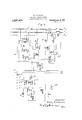
- Figure 1 is a side view of a portion of the automatic routine testing device showing the targets individual to to be tested; Fi i 2 is an end View of the same;
- Fig. 3 is a diagrammatic representation of the circuits and apparatus employedin connection with the structures'shown in Fig. 1 and Fig.2;
- Fig. a is a diagrammatic re'prese'ntationflof the testing device embodying the feature whereby the device is caused to pause in its, operation unti the detected unstandar-d condition is remedied, the part above the broken line being a diagrammatic representation of an automatic co'nnector'switch ofa kind wellknown in the art;
- Fig. dis a diagrammatic representation of another connector switch and a modification of the testing device whereby a test for an unstandard condition is made in a slightly different manner.
- the terminals 1, 2 and 3 represent the terminals of the connector switch as they appear in a preceding selector switch and upon which the brushes of such selector switch may rest. It. will be assumedthat a call has been. initiated by a calling party and has been extended as far as the terminals; 1, 2'and3 in a well-known-manner.
- the seizure of this connector switch is signalized by the placing of a path of low-resistance over the calling line between the terminals 1 and 2.
- a circuit is thereupon established from ground, right-hand winding ofrelay LR, the inner right-hand armature and normal contact of relay LE conductor L, the terminal 2 through thepath of low resistance comprising the subscribers -substa tlon telephone apparatus,
- Relay LR thereupon attracts its armature and establishes a circuit from ground, armature and alternate contact of relay LR, winding of slow-release relay 4 to battery and thence to ground.
- relay 4 attracts itsarmatures and establishes a circuit which extends from ground, left hand armature'and contact of relay 4 to the test wire TW, terminal 3 and thence through well-known circuits including a relay in the line switch (not shown) to battery and ground.
- Relay LR attracts its armatures and establishes a circuit from ground, left-hand armature and contact of relay 1, test wire T'W, contact and outerleft-hand armature of relay LE winding of relay 8 to battery and thence to ground.
- Relay 8 in attracting its armatures, opens at its right-hand armature the energizing circuit for relay 16, thereby preventing-the further flow of ringing current over the called subscribers line.
- Relay 8 also establlshes a locklng circult for ltself extending from ground, left-hand armature and con-' tact'of relay 4, test wire TW, contact and lefthand armaturc of relay 8, winding of relay 8 to battery and thence to ground. In this manner, then, the calling subscriber is put in telephonic communication with the called subscriber.
- Relay LR in retracting its armature allows the deenergizationof relay 4, and establishes a circuit from ground, armature and normal contact oft-slay LR, right hand armature through terminals and normal contact of relay 4:, off-normal switch ON, winding of relay 17 winding-of release magnet 18, to battery and ground.
- the windings or relays l7 and 18, however, are soproportioned that the current flowing through them in series is sufficient to cause the energization of the relay 17 only.
- the routine testing apparatus diagrammatically shown below the broken line is connected to the various connector switches of the type shown above the broken line, t and t
- the brushes F) and b are arranged to travel over and make contact with terminals 2? and 25 Let it be assumed in the first case that no unstandard condition, signalized as before described by a ground on a terminal t", is encountered.
- a stepping magnet SM is rovided which, upon deenergization, steps the brushes 6 and b from association with one set of terminals to the association with the next set of terminals. This stepping magnet is operated in the following manner.
- interrupter I has just reached a point where a'circuit is established from ground, interrupter 1 normal contact and left-hand armature of relay 19, winding of relay 19, winding of slow-acting relay 20, to battery and ground.
- Relay 19 attracts its armatures and establishes a circuit from ground, righthand armature and contact of relay 19,]
- Relay 19 also establishes a circuit from grounded battery, winding of relay 20, winding of relay 19, alternate contact and left-hand armature of relay 19, contact and armature of slow-acting relay 20, to the normal contact of switch 21 and thence to ground.
- Relay 20 is so. designed and adjusted that it will not open its contact under its present energization until suflicient time has elapsed to allow the interrupter I to reach a position where no circuit is completed therethrough. When at last relay 20- does attract its .armature, it
- Bell B is energized in this circuit and is intended to summon an attendant who will remedy the unstandard condition.
- Relay 22 through its outer right-hand from ground, switch 21 and its normal contact, contact and outer right-hand armature of relay 22, left-hand armature and alter nate contact of relay 19, winding of relay 19, winding of relay 20 to battery and thence to ground.
- Relays 19 and 20 are thereby held permanently energized and thus the advance of the brushes 6 and b is prevented until the unstandard condition detected is finally remedied.
- relay 22 Through its left-hand armature and contact, relay 22 extends a ground to the brush b terminal and thence to the test wire TWV of the connector switch which is intended to hold such switch permanently busy until such time as the unstandard condition is remedied. At the same time an alternate circuit is established through the left-hand armature and contact of relay 22 to prevent the release of relay '22 if, due to the vibrations of the frame to which relay When, under the influence armature completes a circuit LE is attached, the unstandard condition 25 in the row or such terminals. The'actuation of the swltch at that time establishes a circuit from ground, alternate contact of switch 21, signal bell B to battery and ground.
- a structural arrangement isdisclosed for identifying a set of terminals through which an unstandard condition in an associated piece of apparatus may be detected;
- Part of a frame F is shown, to which. is rigidly connected a set of terminals t and 27
- Brushes b and b are arranged to travel over andmake contact with these terminals.
- a magnet TM Associated with the brushes is a magnet TM, which is arranged to make physical contact with target T, associated withthat set of terminals t and 25* upon which the brushes 6 and 25* may rest.
- thebrush b encounters the terminal 6 which when grounded denotes the existence of an unstandard condition in the connector switch, the relay 26 responds through a circuit extending from ground, battery, winding of relay 26, brush 5*, terminal.
- t conductor 25 the off-normal contact ON, the normal contact and righthand armature of relay 4, normal contact and armature of relay LR, to ground.
- relay 19 When, now, relay 19 operates, as before described, a circuit is established from ground, the armature and contact of relay 19, left-hand armature and contact of relay 26, winding of tripping magnet TM, to battery, and ground. armature 'and'trips target T, which thereupon establishes a connectionbetween spring S and the terminal 25 The relay 26 attracts its armatures and establishes a circuit from ground, battery, left-hand armature and contact of relay 26, resistance R, brush 6*, the terminal 6*,
- the winding of relay 27 is of comparatively low resistance, and thus a ground is maintained on the test wire of the connector switch, which is intended to hold'such connector switch out of service until the un standard condition is remedied.
- testing device as a whole, is not halted in its operation, but is allowed to'continue stepping from one set of terminals to another in the manner previously described.
- the key K is provided for the purpose of unlocking the relay 27 when an attende ant, in answer to the summons of the bell B remedies the detected unstandard condition.
- FIG. 5 an arrangement is disclosed for testing for nnstandard conditions in a connector switch of aslightly difierent type. That part of Fig. 5, which is above the broken line, is a diagrammatic representation of circuits and apparatus associated with a connector switch, and the part below the broken line represents diagram' matically the testing arrangement.
- the connector switch shown is ofthe well-known type in which the brush carrying spindle is first stepped vertically under the control of external impulsesto bring the brushes opposite the level in which the desired line is to be found, and is then rotated also in response to 7 external control impulses to bring the brush .to the contacts or the de sired line.
- the usual line relay is indicated at 30, the supervisory'relay at 31, the release relay at 32, the primary magnet at 33, cut-off relay at 34, ringing relay at 85, the two slow-acting relays at 36 and 37, the secondary magnet at 39 and the vertical ofinormal switch at ON Side-switch arms are indicated at 40, 41, 42 and 43,
- a common unstandard condition in a con nector switch or this character occurs when such connector is seized or taken for use by a selector switch, its normal operation in extending the connection to the terminalsof the desired line.
- relay 27 In a manner similar to that previously described relay 27 will be energized over a circuit eX- tending from ground, battery, left-hand contact and armature of relay 29, left-hand contact and armature of relay 28, resistance R brush b spring S, winding of relay 27 to ground, and an alarm will be sounded by the bell B What is claimed is:
- means for detecting unstandard conditions in telephone apparatus comprising testing means responsive to a changed electrical condition denoting an unstandard condition, means controlled by said' testing means for clirectly identifying a piece of apparatus in which an unstandard condition has been detected, and'means for automatically and successively associating said testing means with said apparatus to be tested.
- means relay 28 alone will respond, and a for detecting unstandard conditions in telephone apparatus comprising testing means responsive to a changed electrical condition denoting an unstandard condition, means controlled by said testing means for positively identifying a piece of apparatus in which an unstandard condition has been detected, 'means responsive to said identifying means for holding said piece of apparatus out of service until said unstandard condition is remedied, and means for automatically and successively associating said testing means with said pieces of apparatus to be tested.
- means for detecting unstandard conditions in telephone apparatus comprising testing means responsive to a changed electrical condition denoting an unstandard condition, means forholding a piece of apparatus in which an unstandard condition has been detected out of service, and means for automatically and successively associating said testing means with said piecesof apparatus.
- sets of terminals sets of terminals, brushes arranged to travel over and make contact with said terminals, means responsive to a changed electrical condition on one or more of said terminals denoting an unstandard condition for positively identifying such terminals, link circuits extending between said means and said brushes, and means for successively and automatically associating said brushes with each set of said terminals.
- sets of fixed terminals, brushes arranged to travel over and make contact with said terminals, like pieces of electrically connected apparatus joined to said sets of terminals, a means individual to each set of terminals for holding the associated piece of electrically connected apparatus out of service, means responsive to a changed electrical condition on said sets of terminals denoting an un- Copies of this patent may be obtained for individual to each set of terminals for iden- V tifying said terminals when actuated, means cuits extending between said brushes and said responsive means, and means for successlvely and automatlcally assoclatmg said brushes wlth said sets of termlnals.
Description
H. P. CLAUSEN. ELECTRICAL TESTING SYSTEM,
APPLICATION FILED DEC. 29. 1916- Patented Aug. 21, 1917.
3 SHEETS-SHEET I.
y Maker/fan Hen/y f? Hausa/4.
H. P. CLAUSEN. ELECTRICAL TESTING SYSTEM.
APPLICATION FILED DEC-29. I916.
Patented Aug. 21, 1917;
3 SHEETS-SHEET 2.
/n wnfork' (/nry R C/ausen.
H. P. CLAUSEN.
ELECTRICAL TESTINGv SYSTEM.
APPLICATION FILED DEC. 29. I916.
Patented Aug. 21, 1917.
v//7 rem/0r Hen/7 P 6/0036 the pieces of apparatus HENRYP. CLAUSEN, orivroUNT VERNON, NEW YORK, AssIe'NoR'r'o wrisrE RN ELEoraio COMPANY, INCORPORATED, OF
NEW YORK, N. Y., A CORPORATION or NEW YORK.
ELECTRICAL TESTING SYSTEM.
Specification of Letters Patent; Pat t A 21, 1917,
Application filed December 29, 1916. Serial No. 139,562.
To all whom it may concern:
Be it known that I, HENRY P. CLAUSEN, a citizen of the United States, residing at Mount Vernon, in the county of VVestchester and State of New York, have invented certain new and useful Improvements in Electrical Testing Systems, of which the follow ing is a full, clear, concise, and eXact de scription.
This invention relates to electrical testing systems and particularly to that class of systems which is used in telephone exchanges for performing routine tests on telephone apparatus.
The object of the invention is to provide means for successively and automatically testing certain pieces of apparatus for unstandard conditions and for operating a signal and identifying such pieces of apparatus as are found in an unstandard condition and at the same time for holding themout of service untll such unstandard-- condition is remedied. i
A; feature of the invention is theprovision of means for causing an automatic routine testing device to pause in its operation when an unstandard condition is detected and to operate a signal which will summon an attendant. Through the virtue of pausing and thus remainingin association with the pieces of apparatus in which an unstandard condidition is detected, two results are accomplished, the first of which is to indicate positively which piece of apparatus is at fault, and the second of which is to prevent such piece of apparatus from further attempts at giving service.
ilnother feature of the invention, which.
1ust described, 1s
is a modification of that means for tripping atarget associated with the apparatus within which an unstandard condition has arisen and. then Causingthe automatic routine testing device to continue in the performance of its duties. The tripping of the target in this case accomplishes the same results as before, that is, it indicates positively which piece of apparatus is y in an unstandard condition and it holds such piece of apparatus out of-service until the detected unstandard condition isremedied.
In the drawings, Figure 1 is a side view of a portion of the automatic routine testing device showing the targets individual to to be tested; Fi i 2 is an end View of the same; Fig. 3 is a diagrammatic representation of the circuits and apparatus employedin connection with the structures'shown in Fig. 1 and Fig.2; Fig. a is a diagrammatic re'prese'ntationflof the testing device embodying the feature whereby the device is caused to pause in its, operation unti the detected unstandar-d condition is remedied, the part above the broken line being a diagrammatic representation of an automatic co'nnector'switch ofa kind wellknown in the art; and Fig. dis a diagrammatic representation of another connector switch and a modification of the testing device whereby a test for an unstandard condition is made in a slightly different manner. 1
Referring now especially to Fig. l, it is thought that a clear understanding of the} nature of an unstandard condition which may be tested for, will be had from the following detailed description. 1 V
The terminals 1, 2 and 3 represent the terminals of the connector switch as they appear in a preceding selector switch and upon which the brushes of such selector switch may rest. It. will be assumedthat a call has been. initiated by a calling party and has been extended as far as the terminals; 1, 2'and3 in a well-known-manner. The seizure of this connector switch is signalized by the placing of a path of low-resistance over the calling line between the terminals 1 and 2. A circuit is thereupon established from ground, right-hand winding ofrelay LR, the inner right-hand armature and normal contact of relay LE conductor L, the terminal 2 through thepath of low resistance comprising the subscribers -substa tlon telephone apparatus,
conductor L normal contact and inner leftthe terminal 1, the v hand armature of relay LE left-hand win ding of relay LE, to battery and thenceto ground. Relay LR thereupon attracts its armature and establishes a circuit from ground, armature and alternate contact of relay LR, winding of slow-release relay 4 to battery and thence to ground. In turn, relay 4 attracts itsarmatures and establishes a circuit which extends from ground, left hand armature'and contact of relay 4 to the test wire TW, terminal 3 and thence through well-known circuits including a relay in the line switch (not shown) to battery and ground.
' The subscriber now manipulates his. an
1 sistance extending between a circuit from contact of relay LR, right-hand armature I however,
pulse transmitter, thereby intermittently opening and closing the path of low reterminals 1 and 2 and causing-the rapid vibration of the armature of relay LR. The first retraction of its armature by the relay LR establishes ground, armature and normal and alternate contact of relay 1, winding of slow-release relay 5, Winding of primary magnet 6, 'first position contact and sideswitch arm 7, right-hand armature and contact of relay8, to battery and ground. Relays 5and '6 areenergized in this circuit. Relay 5 being slow to release does not subsequently release until after the full series of impulses has been transmitted. Relay 6, responds to each separate impulse andthereby causes the group selecting operation of the brushes 9, 10 and 11 in accordance with the setting of the subscribers impulse transmitter.
The energizati-on of relay 5 results in the establishment of a circuit from ground, ar-
'mature and contact of relay 5, winding of relay 12 to battery and ground.- Relay 12 attracts its armature while energized, and upon deenergization, in response to the deenergizationof relay 5, it causes the movement of slde-swltch arms 7 and 13 into the second position. 1
.The last manipulation of the impulse transmitter by the calling subscriber causes the transmission of impulses through .a circuit which now extends from ground, armature and normal contact of relay LR, righthand armature and alternate'contact of relay 4E, winding of relay 5, winding of secondary'magnet 14, second position contact and side-switch arm 7 and thence over the circuit previously traced. The secondary magnet 14L,'responding to the separate impulses, drives the brushes 9, 10 and 11 into association with the terminals of the desiredof relay 5, drives the side-switch arms 7 and 13 into their third position. i
In thisposition, a circuit is established from ground, the third position contact and ,side-switch arm 13, armature and contact third position contact of relay 12, winding of relay 15 tobattery and ground. Relay 15 attracts its'armatures and extends the talking conductors of the connector switch L and L to the brushes ;10' and 11 and from thence over the con- 60 7 right-hand armature and contact of relay At the end of this series ofimpulses, line relay LR" permanently attractsitsarmature, therebyopening the cir-- cuit just described. Relay 5 again deenergizes, and relay 12, responding to the action 8 to battery and ground. Under the influence of interrupterI, relay 16 intermittently attracts and retracts its armatures. During the interval in. which these armatures are attracted, ringing current is transmitted over a circuit extending from the generator G, alternate contact and inner armature of relay 16, inner armature and contact of relay 15, brush 10, conductors and apparatus of the called subscribers substation, brush 11, contact and outer armature tact of relay 15, brush 11, through the brushes and apparatus of the subscribers substation, brush 10, contact and inner armature of relay 15, inner armature and normal contact of relay 16, lower conductor L, left-hand winding of relay LR to battery and thence to ground. Relay LR attracts its armatures and establishes a circuit from ground, left-hand armature and contact of relay 1, test wire T'W, contact and outerleft-hand armature of relay LE winding of relay 8 to battery and thence to ground. Relay 8, in attracting its armatures, opens at its right-hand armature the energizing circuit for relay 16, thereby preventing-the further flow of ringing current over the called subscribers line. Relay 8 also establlshes a locklng circult for ltself extending from ground, left-hand armature and con-' tact'of relay 4, test wire TW, contact and lefthand armaturc of relay 8, winding of relay 8 to battery and thence to ground. In this manner, then, the calling subscriber is put in telephonic communication with the called subscriber.
Let us now assume that an unstandard condition exists in the connector switch,
which may be described as a dirty or unreliable contact at the outermost right-hand armature of relay LE When, at the conlot clusion of the conversation between the calling and the called party, both havereplaced their receivers on their hooks, the paths of low resistance, extending in one case between the termlnals 1 and .2, and in the other case between the brushes 10 and 11, will be removed, whereupon both relays LR and LR will retract their armatures. Relay LR in retracting its armature allows the deenergizationof relay 4, and establishes a circuit from ground, armature and normal contact oft-slay LR, right hand armature through terminals and normal contact of relay 4:, off-normal switch ON, winding of relay 17 winding-of release magnet 18, to battery and ground. The windings or relays l7 and 18, however, are soproportioned that the current flowing through them in series is sufficient to cause the energization of the relay 17 only. It thereupon attracts its armature and establishes a circuit from ground, armature and contact of-relay l7, winding ofrelay 8, to battery and ground, thus maintaining the energization of the latter relay and at the same time preserving the ground on the test wire TVV through the left-hand armature and contact of relay '8. The right-hand armature and contact of relay LR is intended to short-circuit relay 17 and cause the energization of relay 18, but due to the unstandard condition this energization does not occur, and'the brushes 9, 10 and 11 are left in association with the called subscribers telephone line. The ground 'on the conductor extending between the off-normal switch ON and-the winding of relay 17 constitutes a changed electrical condition at this point, indicating such an unstandard condition.
The routine testing apparatus diagrammatically shown below the broken line is connected to the various connector switches of the type shown above the broken line, t and t The brushes F) and b are arranged to travel over and make contact with terminals 2? and 25 Let it be assumed in the first case that no unstandard condition, signalized as before described by a ground on a terminal t", is encountered. A stepping magnet SM is rovided which, upon deenergization, steps the brushes 6 and b from association with one set of terminals to the association with the next set of terminals. This stepping magnet is operated in the following manner. Let it be assumed that the interrupter I has just reached a point where a'circuit is established from ground, interrupter 1 normal contact and left-hand armature of relay 19, winding of relay 19, winding of slow-acting relay 20, to battery and ground. Relay 19 attracts its armatures and establishes a circuit from ground, righthand armature and contact of relay 19,]
winding of stepping magnet SM to battery and thence to ground. Relay 19 also establishes a circuit from grounded battery, winding of relay 20, winding of relay 19, alternate contact and left-hand armature of relay 19, contact and armature of slow-acting relay 20, to the normal contact of switch 21 and thence to ground. Relay 20 is so. designed and adjusted that it will not open its contact under its present energization until suflicient time has elapsed to allow the interrupter I to reach a position where no circuit is completed therethrough. When at last relay 20- does attract its .armature, it
opens the energizing circuit for the two relays .19 and 20, whichthereupon become deenergized. Through the agency ofthestepping magnet SM the brushes 7) and b are advanced into association with the next connector switch to be tested.
Let it be assumed that these brushes now rest on the terminals 16 and t of a connector switch in which the described unstandard condition exists. of the stepping magnet SM, the brushes 6 and b are advanced into association with the terminals 2% and t the ground existing on the conductor extending between the OH- normal switch and the relay 17 and which extends to the terminal 16, now extends through the brush 7), winding of relay 22, to battery and ground. Relay 22 attracts its armatures. WVhen under the influence of interrupter I relays 19 and 20 are energized, a circuit is established between ground, right-hand armature and contact of relay 19, inner right-hand armature and contactof relay 22 to the signal bell B to battery and ground. Bell B is energized in this circuit and is intended to summon an attendant who will remedy the unstandard condition. Relay 22 through its outer right-hand from ground, switch 21 and its normal contact, contact and outer right-hand armature of relay 22, left-hand armature and alter nate contact of relay 19, winding of relay 19, winding of relay 20 to battery and thence to ground. Relays 19 and 20 are thereby held permanently energized and thus the advance of the brushes 6 and b is prevented until the unstandard condition detected is finally remedied.
Through its left-hand armature and contact, relay 22 extends a ground to the brush b terminal and thence to the test wire TWV of the connector switch which is intended to hold such switch permanently busy until such time as the unstandard condition is remedied. At the same time an alternate circuit is established through the left-hand armature and contact of relay 22 to prevent the release of relay '22 if, due to the vibrations of the frame to which relay When, under the influence armature completes a circuit LE is attached, the unstandard condition 25 in the row or such terminals. The'actuation of the swltch at that time establishes a circuit from ground, alternate contact of switch 21, signal bell B to battery and ground.
The ringing of this signal bell notifies the attendant that the test performed by the present testing device has been completed and he may reset the brushes 7) and Z2 by hand. on the first set of terminals, such as t and 25 ready for a second series-0t tests.
In the embodiment of the invention shown inFigs. 1 and 2, a structural arrangement isdisclosed for identifying a set of terminals through which an unstandard condition in an associated piece of apparatus may be detected; Part of a frame F is shown, to which. is rigidly connected a set of terminals t and 27 Brushes b and b are arranged to travel over andmake contact with these terminals. Associated with the brushes is a magnet TM, which is arranged to make physical contact with target T, associated withthat set of terminals t and 25* upon which the brushes 6 and 25* may rest. The operation of the tripping magnet TM actuates the target T, which is pivoted'to a spring S in such a manner that when actuated, the spring S, due to its resiliency, will make electrical contact with the terminal i The operation of this device will now be described in connection with the circuits shown diagrammatically in Fig. 3. The conductors 24 and 25, connected to the terminals t and Z4 lead from the same points in the circuit of the connector switch as the terminals 6 and t in Fig. 4. The operation of the relays 19 and 20 is the same as in Fig. 4, but the operation of the device, as a whole, is somewhat different.
l/Vhen thebrush b encounters the terminal 6 which when grounded denotes the existence of an unstandard condition in the connector switch, the relay 26 responds through a circuit extending from ground, battery, winding of relay 26, brush 5*, terminal. t conductor 25, the off-normal contact ON, the normal contact and righthand armature of relay 4, normal contact and armature of relay LR, to ground.-
When, now, relay 19 operates, as before described, a circuit is established from ground, the armature and contact of relay 19, left-hand armature and contact of relay 26, winding of tripping magnet TM, to battery, and ground. armature 'and'trips target T, which thereupon establishes a connectionbetween spring S and the terminal 25 The relay 26 attracts its armatures and establishes a circuit from ground, battery, left-hand armature and contact of relay 26, resistance R, brush 6*, the terminal 6*,
the winding pgt relay 27, and thence t Magnet TM attracts its ground. 9 Relay 27 .is energized in this circuit and attracts its armature, and thereupon a locking circuit is established from ground, winding of relay 27, the key K resistance R the contact and right-hand armature of relay 27, to battery, I and ground. At its left-hand armature a circuit is established from ground, left-hand armature and contact of relay 27, the bell B to battery, and ground. The energization of bell B causes its actuation, and through the alarm thus sounded an attend ant is summoned to remedy the detected unstandard condition.
The winding of relay 27 is of comparatively low resistance, and thus a ground is maintained on the test wire of the connector switch, which is intended to hold'such connector switch out of service until the un standard condition is remedied.
It should be noted that in this instance the testing device, as a whole, is not halted in its operation, but is allowed to'continue stepping from one set of terminals to another in the manner previously described.
The key K is provided for the purpose of unlocking the relay 27 when an attende ant, in answer to the summons of the bell B remedies the detected unstandard condition.
In the embodiment of the invention shown in Fig. 5, an arrangement is disclosed for testing for nnstandard conditions in a connector switch of aslightly difierent type. That part of Fig. 5, which is above the broken line, is a diagrammatic representation of circuits and apparatus associated with a connector switch, and the part below the broken line represents diagram' matically the testing arrangement. The connector switch shown is ofthe well-known type in which the brush carrying spindle is first stepped vertically under the control of external impulsesto bring the brushes opposite the level in which the desired line is to be found, and is then rotated also in response to 7 external control impulses to bring the brush .to the contacts or the de sired line. The usual line relay is indicated at 30, the supervisory'relay at 31, the release relay at 32, the primary magnet at 33, cut-off relay at 34, ringing relay at 85, the two slow-acting relays at 36 and 37, the secondary magnet at 39 and the vertical ofinormal switch at ON Side-switch arms are indicated at 40, 41, 42 and 43,
A common unstandard condition in a con nector switch or this character occurs when such connector is seized or taken for use by a selector switch, its normal operation in extending the connection to the terminalsof the desired line.
As soon as the connector has been taken for use, a ground is placed upon the conductor l5, due to the operation of the line relay and has failed to complete 30. If, on the other hand, the operation of the connector has proceeded inthe standard manner, there will also be a ground on brush eta through the side-switch arm 41 in position 3. Themanner in which the test arrangement distinguishes"between these two conditions will best be understood from a description of the operation of making such testa The corresponding terminals 44L, a6, and conductors 45 of a plurality of connector switches, are connected to rows of terminals 25 t and t of a testing device. The brushes 7) and b are arranged to travel over and make contact with these terminals.
The test performed in this instance is similar to that described in connection with Fig. 3. In this case, however, two relays are provided in place of one, such as 26. Should an idle condition be detected then neither the relay 28 or 29 will respond and the tripping magnet TM will not be actuated. Should a standard busy condition be detected both relays 28 and 29 will be actuated, but in this case, the tripping magnet TM will not be energized, since its circuit, which is closed first through the right-hand armature and contact of relay 28, has been opened at the right-hand armature and contact of relay 29; the relay 29 being a fast relay, and relay 28 being a slow acting relay.
Should an unstandard condition be detected, circuit will be established from ground, right-hand armature, contact of relay 19, right-hand armature and contact of relay 28, right-hand armature and contact of relay 29, winding of tripping magnet TM, to battery, and ground. Target T will be tripped and the spring S will come in corn tact with the terminal t whereby a ground is placed, as before, on the test terminal of the connector switch under test. In a manner similar to that previously described relay 27 will be energized over a circuit eX- tending from ground, battery, left-hand contact and armature of relay 29, left-hand contact and armature of relay 28, resistance R brush b spring S, winding of relay 27 to ground, and an alarm will be sounded by the bell B What is claimed is:
1. In an electrical testing system, means for detecting unstandard conditions in telephone apparatus comprising testing means responsive to a changed electrical condition denoting an unstandard condition, means controlled by said' testing means for clirectly identifying a piece of apparatus in which an unstandard condition has been detected, and'means for automatically and successively associating said testing means with said apparatus to be tested.
2. In an electrical testing system, means relay 28 alone will respond, and a for detecting unstandard conditions in telephone apparatus comprising testing means responsive to a changed electrical condition denoting an unstandard condition, means controlled by said testing means for positively identifying a piece of apparatus in which an unstandard condition has been detected, 'means responsive to said identifying means for holding said piece of apparatus out of service until said unstandard condition is remedied, and means for automatically and successively associating said testing means with said pieces of apparatus to be tested.
3. In an electrical testing system, means for detecting unstandard conditions in telephone apparatus comprising testing means responsive to a changed electrical condition denoting an unstandard condition, means forholding a piece of apparatus in which an unstandard condition has been detected out of service, and means for automatically and successively associating said testing means with said piecesof apparatus.
4. In an electrical testing device, sets of terminals, brushes arranged to travel over and make contact with said terminals, means responsive to a changed electrical condition on one or more of said terminals denoting an unstandard condition, means for positively identifying a set of terminals on which-an unstandard conditionhasbeen detected, and means for successively and automatically associating said responsive means through said brushes with each set of said terminals.
5. In an electrical testing device, sets of terminals, brushes arranged to travel over and make contact with said terminals, means responsive to a changed electrical condition on one or more of said terminals denoting an unstandard condition for positively identifying such terminals, link circuits extending between said means and said brushes, and means for successively and automatically associating said brushes with each set of said terminals.
6. In an electrical testing device, sets of terminals, brushes arranged to travel over and make contact with said terminals, like pieces of electrically connected apparatus joined to each set of said terminals, means for holding a piece of such apparatus out of service, said means being responsive to a changed electrical condition on one or more of said terminals denoting an unstandterminals, brushes arranged to travel over and make contact with said terminals, like pieces of electrically connected apparatus joined to each set oit'said terminals, means for positively ldentifymg such a piece of apparatus, said means belng responsive to a changed electrical condition denoting an unstandard condltlon, link conductors extending between said brushes and said responsive means, means for holdlng a piece of apparatus on which an unstandard condition has been detected out of service, and
means for successively and automatically associating said brushes with'said terminals.
8. In an electrical testing device, sets of fixed terminals, brushes arranged to travel over and make contact with said terminals, like pieces of electrically connected apparatus joined to said sets of terminals, a means individual to each set of terminals for holding the associated piece of electrically connected apparatus out of service, means responsive to a changed electrical condition on said sets of terminals denoting an un- Copies of this patent may be obtained for individual to each set of terminals for iden- V tifying said terminals when actuated, means cuits extending between said brushes and said responsive means, and means for successlvely and automatlcally assoclatmg said brushes wlth said sets of termlnals.
10. In an electrical testing device, sets of fixed terminals, brushes arranged to travel over and make contact with said terminals, like pieces of electrically connected apparatus joined to said setsof terminals, means individual to each set of terminals for iden tifying said terminals when actuated, said identifying means When actuated also serving tohold the associated piece of apparatus out of service, means responsive to a changedv electrical condition on said terminals denoting an unstandard condition in said associated apparatus for controlling said identifying means, link circuits extending between said brushes and said responsive means, and means for successively and automatically associating said brushes with said sets of terminals.
In witness whereof, I hereunto subscribe my name this 28th day of December, A. D.,
HENRY P. OLAUSEN.
five cents each, by addressing the Commissioner of Patents. Washington, D. O.
Priority Applications (1)
| Application Number | Priority Date | Filing Date | Title |
|---|---|---|---|
| US13956216A US1237477A (en) | 1916-12-29 | 1916-12-29 | Electrical testing system. |
Applications Claiming Priority (1)
| Application Number | Priority Date | Filing Date | Title |
|---|---|---|---|
| US13956216A US1237477A (en) | 1916-12-29 | 1916-12-29 | Electrical testing system. |
Publications (1)
| Publication Number | Publication Date |
|---|---|
| US1237477A true US1237477A (en) | 1917-08-21 |
Family
ID=3305296
Family Applications (1)
| Application Number | Title | Priority Date | Filing Date |
|---|---|---|---|
| US13956216A Expired - Lifetime US1237477A (en) | 1916-12-29 | 1916-12-29 | Electrical testing system. |
Country Status (1)
| Country | Link |
|---|---|
| US (1) | US1237477A (en) |
-
1916
- 1916-12-29 US US13956216A patent/US1237477A/en not_active Expired - Lifetime
Similar Documents
| Publication | Publication Date | Title |
|---|---|---|
| US1237477A (en) | Electrical testing system. | |
| US2172947A (en) | Telephone system | |
| US2233282A (en) | Telephone system | |
| US1679567A (en) | Automatic telephone system | |
| US1394642A (en) | Electric signaling system | |
| US2370239A (en) | Special service telephone system | |
| US1585909A (en) | Code signaling system | |
| US2038222A (en) | Telephone system | |
| US1729980A (en) | Selector switch | |
| US2299514A (en) | Telephone system | |
| US1237476A (en) | Electrical testing system. | |
| US1291587A (en) | Two-wire party-line lock-out telephone system. | |
| US2773138A (en) | Telephone line selecting system | |
| US2899503A (en) | Dial telephone system arranged for machine | |
| US1196876A (en) | Automatic telephone and supervisory system. | |
| US1605734A (en) | Automatic telephone system | |
| US1089404A (en) | Fire-alarm signal-box for automatic telephone systems. | |
| US1188929A (en) | Automatic telephone-exchange system. | |
| US1343903A (en) | Telephone -system | |
| US1337753A (en) | Supervisory system | |
| US1551170A (en) | Automatic telephone system | |
| US2719881A (en) | Line finder for step-by-step telephone system | |
| US2806087A (en) | Stopping circuit for selector switch | |
| US1224140A (en) | Automatic testing system. | |
| US1246548A (en) | Testing arrangement for telephone-exchange systems. |