US1237356A - Holddown for lasting-machines. - Google Patents
Holddown for lasting-machines. Download PDFInfo
- Publication number
- US1237356A US1237356A US13045716A US13045716A US1237356A US 1237356 A US1237356 A US 1237356A US 13045716 A US13045716 A US 13045716A US 13045716 A US13045716 A US 13045716A US 1237356 A US1237356 A US 1237356A
- Authority
- US
- United States
- Prior art keywords
- hold
- plate
- finger
- lasting
- linger
- Prior art date
- Legal status (The legal status is an assumption and is not a legal conclusion. Google has not performed a legal analysis and makes no representation as to the accuracy of the status listed.)
- Expired - Lifetime
Links
Images
Classifications
-
- A—HUMAN NECESSITIES
- A43—FOOTWEAR
- A43D—MACHINES, TOOLS, EQUIPMENT OR METHODS FOR MANUFACTURING OR REPAIRING FOOTWEAR
- A43D23/00—Single parts for pulling-over or lasting machines
- A43D23/02—Wipers; Sole-pressers; Last-supports; Pincers
- A43D23/022—Sole-pressers
Definitions
- This invention ⁇ relates yto hold-downs for i lasting machines and particularly to new and improved means ⁇ for holdinga holddown J plate upon its supporting@ finger.
- Theftoe portion of the upper ⁇ of a shoe usually has placed between theupper and the lining a piece of stiffeni-ng' material, for This stidenery with the upper materials forms, inthe lastexample, leather or fabric.
- the stiffener or ⁇ stifi'ening material which is inserted ⁇ between the upper and the lining is frequently referred to as the toe box.
- toe stiffener'for toe box ⁇ composed of a piece of felt or other fabric impregnated with a cementitious substance. ⁇ which prior to the lasting operation has to e be softened by steaming or by heat otherwise applied and which by the time the last- ⁇ ing operation has been completedhas cooledv and set. ⁇ e
- the construction y provides means for preventing detachment of the plateby stress tending to produce relative movement of the plates and finger, longitudinally of the linger, that is, ⁇ length wise of the shoe, while at 'the same time affording convenient means for detachment of( y the plate from thewfinger by lrelative movement of the plate and finger ⁇ laterally of the finger in one direction.
- Fig. 2 is a side kview of the hold-down showing the shoe 4inlongitudinal section
- ⁇ and ⁇ Fig. I3 is a perspective view showing the under side of the hold-down finger.
- the vertically movable post by which the hold-down is operated to apply pressure to the shoe bottom is indicated at 2.
- the post 2 carries rotatably mounted thereon a block 4 through which a hold-down arm 6 extends and in which it is movable for lateral adjustment of the h0lddown.
- a block 8 At the outer end of the arm 6 is mounted a block 8 having a slot 10 through which a hold-,down finger 12 extends.
- a rrelatively resilient member 14 Beneath the linger 12 and passing with it through the'slot 10 is a rrelatively resilient member 14 and both the linger and the member 14 are' retained in the block 8 by pins 16 which engage notches in the opposite edgesof the linger 12 and the member 14.
- the pins are fixed in a member 17 having a stud 18 which is movable vertically against e a -leaf spring 20 to permit kthe lpins to be raised above the linger 12 and 'the member ⁇ 14 and allow their removal from the slot 10.
- the block 8 is connected to a torsion ⁇ spring 22 passing longitudinally through the arm 6 by which the forward end of the finger is held yieldingly toward the shoe.
- the forward end of the finger 12 has in its lower face a recess in which is seated' the upper facer of the head 24 of a rstud 26 which is fixed in a hold-down plate 28.
- the resilient member 14 Underlying the head 24 of the studV isthe resilient member 14 whi'clihas al slot 30 Wide enoughv to admit the stem- 26 of the stud but not Wide enoughto permit the head 24 to pass through it.
- the slot 30 eXtend'slaterally of the member 14 and hence prevents relative movement' of the stud and linger' longitudinally of the linger andwvhen the parts are in operative position as shown in F ig. l 4relative movement of :these parts longitudinally of the shoe is prevented.
- a hold-down the combination of a hold-down plate, a hold-down finger, and means for holding the plate upon the finger constructed and arranged to prevent relative movement'of' the plate and nger longif tudinally of the finger and permitting separation of the plate and finger by relative lateral movement of vthe plate and linger.
- a hold-down linger arranged to extend longitudinally of the shoe WheninI operative position, a hold-down plate, a stud on the plate having an enlargement and adapted to bear on theunder side of the iinger, and a ⁇ stud retaining member comprising a flat spring havingv a slot opening at one side of the linger and adapted to engage the stud below the enlargement.
- a hold-down for lasting machines comprising an arm extending transversely across a shoe bottom, a finger secured 5to the arm and having a concavit'y in the end opposite thearm, a hold-down plate having aprojection adapted to engage the concavity, and means comprising a flat spring having a slot open at one side of the linger for holding the projection in the concavity.
Description
A.A. MAcLEoD. HOLDDOWN FOR LASTING MACHINES.
'K APPLICATION FILEDKNOV. 9.1916- 1,237,356. Patented Aug. 2i, 1917.
ALBERTA. MACLEOD, or swnivirscoar, iviAssAciiUsETTs, Assienon To UNITED SHOE MACHINERY COMYANY, OIEPATERSQN, JERSEY, CDRPORATION OFVVNEW JERSEY.
To all. whom t may concern: l s .f
Be vit known that I, ALBERTA.' MAGLEOD, a
citizen of the UnitedStates, `fresiding` at Swampscott, in the county of Essex andv State of Massachusetts, have invented certain Improvements in Holddowns forLasting-Machines, of which the following description, inl' connection' with `the .accom` panying drawings, is a specification, likeref# erence characters on the` drawings indicating like parts in the several figures.
This invention` relates yto hold-downs for i lasting machines and particularly to new and improved means` for holdinga holddown J plate upon its supporting@ finger. A,
hold-down of a type to lwhich a construction embodying this rinvention is applicable ,isy shown and describedin United vStates Letters Patent No. 1,188,403,` grantedJune 27, 1916, onapplication of Louis M; Brown.: x
Theftoe portion of the upper` of a shoe usually has placed between theupper and the lining a piece of stiffeni-ng' material, for This stidenery with the upper materials forms, inthe lastexample, leather or fabric.
ed shoe, the box toe. The stiffener or `stifi'ening material which is inserted `between the upper and the lining is frequently referred to as the toe box. ,i
Recently, there hask come into extensive,
commercial use a toe stiffener'for toe box` composed of a piece of felt or other fabric impregnated with a cementitious substance.` which prior to the lasting operation has to e be softened by steaming or by heat otherwise applied and which by the time the last-` ing operation has been completedhas cooledv and set.` e
When hold-downs having the construction f shown-in the patent above referred yto are used in lasting shoes provided with a toe boX of thekind above referred to, `it has kbeen found that frequently the hold-downplate sticks quite securely to thev` innersole and innersole rib for the reason that some of the heat softened cementitious" substance with which the toe boXy issaturated issqueezed out by the pressure of the wipers in the lasting operation and subsequently hardens in contact with the plate andk innersole. -Under ksuch conditions when the holdrdown pres` sure is released and the hold-down arm is swung into ino erative position, the plate may adhere su ciently to thek innersole to finger.
y e noLDDowN Eon LAsinvefiviAcHmEs.
specification of Lettverraem. n Patented Aug, 21, 1917 Appiicatio med Nvembepre, 191e. serial No. 130,457.
cause theplate to become detached from the feature of the present invention kconsists e,
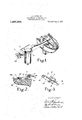
in improved plate 4attaching. mechanism which, while affording means for the ready-t detachmentof the plate, will insure that the plate remain attached to its supporting fine gerdu'ring operation of the machine to do its work; Asshown herein, the construction y provides means for preventing detachment of the plateby stress tending to produce relative movement of the plates and finger, longitudinally of the linger, that is,\length wise of the shoe, while at 'the same time affording convenient means for detachment of( y the plate from thewfinger by lrelative movement of the plate and finger `laterally of the finger in one direction. lIn `the drawings,` Y `Figure 1 is a yperspective view of a holddownembodying thisinvention; f f
Fig. 2 is a side kview of the hold-down showing the shoe 4inlongitudinal section;
` and `Fig. I3 is a perspective view showing the under side of the hold-down finger.
Referring to Fig. 1, the vertically movable post by which the hold-down is operated to apply pressure to the shoe bottom is indicated at 2. The post 2 carries rotatably mounted thereon a block 4 through which a hold-down arm 6 extends and in which it is movable for lateral adjustment of the h0lddown. e At the outer end of the arm 6 is mounted a block 8 having a slot 10 through which a hold-,down finger 12 extends.
Beneath the linger 12 and passing with it through the'slot 10 is a rrelatively resilient member 14 and both the linger and the member 14 are' retained in the block 8 by pins 16 which engage notches in the opposite edgesof the linger 12 and the member 14.
The pins are fixed in a member 17 having a stud 18 which is movable vertically against e a -leaf spring 20 to permit kthe lpins to be raised above the linger 12 and 'the member `14 and allow their removal from the slot 10. The block 8 is connected to a torsion` spring 22 passing longitudinally through the arm 6 by which the forward end of the finger is held yieldingly toward the shoe.
The forward end of the finger 12 has in its lower face a recess in which is seated' the upper facer of the head 24 of a rstud 26 which is fixed in a hold-down plate 28. Underlying the head 24 of the studV isthe resilient member 14 whi'clihas al slot 30 Wide enoughv to admit the stem- 26 of the stud but not Wide enoughto permit the head 24 to pass through it. The slot 30 eXtend'slaterally of the member 14 and hence prevents relative movement' of the stud and linger' longitudinally of the linger andwvhen the parts are in operative position as shown in F ig. l 4relative movement of :these parts longitudinally of the shoe is prevented. Hence if in the operation of lasting: the `toe the' plate should lstick to the Vinner-'sole or upper materials it would be pulled-away When the hold-doWn pressureis' released and the arm 6 isA swung." into inoperative position about the post 2. l/Vhen' it isdesired to-remove thep'late romtheinger, however,
itis only necessary to spring downwardly and having a slot open at a lateral side of the finger.
2. In a hold-down, the combination of a hold-down plate, a hold-down finger, and means for holding the plate upon the finger constructed and arranged to prevent relative movement'of' the plate and nger longif tudinally of the finger and permitting separation of the plate and finger by relative lateral movement of vthe plate and linger.
3. In a hold-down for lasting machines, a hold-down linger arranged to extend longitudinally of the shoe WheninI operative position, a hold-down plate, a stud on the plate having an enlargement and adapted to bear on theunder side of the iinger, and a` stud retaining member comprising a flat spring havingv a slot opening at one side of the linger and adapted to engage the stud below the enlargement.
4. A hold-down for lasting machines comprising an arm extending transversely across a shoe bottom, a finger secured 5to the arm and having a concavit'y in the end opposite thearm, a hold-down plate having aprojection adapted to engage the concavity, and means comprising a flat spring having a slot open at one side of the linger for holding the projection in the concavity.
` In testimony whereof I have .signed my nainey to this specilication.
f f ALBERT A. MACLEOD.
Copies of this patent may b'ev obtinedfor vecents each, by addressing the Commis-.sinner ofy Patents,`
Washington, D. 0.7
Priority Applications (1)
| Application Number | Priority Date | Filing Date | Title |
|---|---|---|---|
| US13045716A US1237356A (en) | 1916-11-09 | 1916-11-09 | Holddown for lasting-machines. |
Applications Claiming Priority (1)
| Application Number | Priority Date | Filing Date | Title |
|---|---|---|---|
| US13045716A US1237356A (en) | 1916-11-09 | 1916-11-09 | Holddown for lasting-machines. |
Publications (1)
| Publication Number | Publication Date |
|---|---|
| US1237356A true US1237356A (en) | 1917-08-21 |
Family
ID=3305175
Family Applications (1)
| Application Number | Title | Priority Date | Filing Date |
|---|---|---|---|
| US13045716A Expired - Lifetime US1237356A (en) | 1916-11-09 | 1916-11-09 | Holddown for lasting-machines. |
Country Status (1)
| Country | Link |
|---|---|
| US (1) | US1237356A (en) |
-
1916
- 1916-11-09 US US13045716A patent/US1237356A/en not_active Expired - Lifetime
Similar Documents
| Publication | Publication Date | Title |
|---|---|---|
| US1237356A (en) | Holddown for lasting-machines. | |
| US942133A (en) | Sole-pressing pad. | |
| US421763A (en) | Andrew w | |
| US958041A (en) | Top-lift holder for heeling-machines. | |
| US1188620A (en) | Lasting-machine. | |
| US1157729A (en) | Lasting-machine. | |
| US1331616A (en) | Holddown for lasting-machines | |
| US2094638A (en) | Shoe coating apparatus | |
| US1108100A (en) | Heel-lasting mechanism. | |
| US1188403A (en) | Holddown for lasting-machines. | |
| US3222703A (en) | Lasting machine | |
| US2878497A (en) | Toe lasting machines for stitchdown shoes | |
| US2189943A (en) | Machine for use in applying pressure to shoe bottoms | |
| US594179A (en) | Lasting-machine | |
| US2278428A (en) | Lasting machine | |
| US1198430A (en) | Work-support. | |
| US560716A (en) | Haeey d | |
| US1516485A (en) | Last clasp for lasting machines and method of making it | |
| US2072838A (en) | Last and last attachment | |
| US1717387A (en) | Shoe-pressing machine | |
| US1422806A (en) | Bed-laster end clasp | |
| US2923953A (en) | courchene | |
| US640990A (en) | Last. | |
| US955509A (en) | Rubber sole-protector for boots and shoes. | |
| US1047387A (en) | Holddown for lasting-machines. |