US1237331A - Assemblage of internal-combustion engines and their associated mechanisms. - Google Patents
Assemblage of internal-combustion engines and their associated mechanisms. Download PDFInfo
- Publication number
- US1237331A US1237331A US5595615A US5595615A US1237331A US 1237331 A US1237331 A US 1237331A US 5595615 A US5595615 A US 5595615A US 5595615 A US5595615 A US 5595615A US 1237331 A US1237331 A US 1237331A
- Authority
- US
- United States
- Prior art keywords
- shaft
- casing
- assemblage
- pump
- shafts
- Prior art date
- Legal status (The legal status is an assumption and is not a legal conclusion. Google has not performed a legal analysis and makes no representation as to the accuracy of the status listed.)
- Expired - Lifetime
Links
Images


Classifications
-
- F—MECHANICAL ENGINEERING; LIGHTING; HEATING; WEAPONS; BLASTING
- F02—COMBUSTION ENGINES; HOT-GAS OR COMBUSTION-PRODUCT ENGINE PLANTS
- F02B—INTERNAL-COMBUSTION PISTON ENGINES; COMBUSTION ENGINES IN GENERAL
- F02B67/00—Engines characterised by the arrangement of auxiliary apparatus not being otherwise provided for, e.g. the apparatus having different functions; Driving auxiliary apparatus from engines, not otherwise provided for
- F02B67/04—Engines characterised by the arrangement of auxiliary apparatus not being otherwise provided for, e.g. the apparatus having different functions; Driving auxiliary apparatus from engines, not otherwise provided for of mechanically-driven auxiliary apparatus
Definitions
- IfJAMEs. G. HEASLET a citizen of the United States of America, and resident of Detroit, in the county of Wayne and State of Michigan, have invented certain new and useful Improved Assemblage of Internal-Combustion Engines and Their Associated Mechanisms, of which the following is a specification.
- This invention relates to an improved assemblage of an internal combustion engine with those mechanisms with which it is necessarily associated for purposes of operation, the object being to assemble said associated mechanisms in agroup at one end of the motor casing, and in a motor vehicle at that point between the motor and the radiator.
- I refer The associated mechanisms to which I refer are the following; the valve control, spark control, the pump, generator, and in some cases, electric starter.
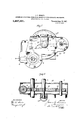
- Figure 1 is a front elevation of the device taken on a line just rearwardly from the starter mechanism hereafter to be described.
- Fig. 2 is a horizontal section of Fig. 1 taken on the line m-a:.
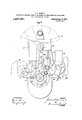
- Fig. 3 is a front diagrammatic View of the assembled mechanisms.
- Fig. 4 is a plan view of the same.
- Fig. 5 is a detail showing the generator mounting in association with the lubricator casing.
- 1 indicates the motor cylinders.
- 2 is the main shaft of the motor which protrudes from the front of the motor casing.
- 3 is a shaft suitably mounted to control the valve operating mechanism.
- 4 is a shaftsuitably mounted to operate the rotary pum 5 is an electric generator armature sha t.
- 6 is a shaft operating a spark control mechanism.
- 7 is the armature shaft of an electric motor.
- the main shaft of the motor, the valve shaft, the pump shaft and the electric motor armature shaft are all parallel, whereas the generator shaft and the spark control shaft are perpendicular to a plane passing throughthe axis of gear mounted at the end of the valve shaft 1 3, while 12 is a corresponding beveled gear mounted on the spark shaft 6, said beveled gears being in mesh.
- 12 is a corresponding beveled gear mounted on the spark shaft 6, said beveled gears being in mesh.
- 13 is a casing inclosing all of the train of gears last described.
- the sleeve 30 adapted to contain the generator shaft 5 and its supporting mechanism.
- This sleeve is provided at the upper end thereof with the port 31 and the tongue 32.
- At the base thereof it is adapted tocontain the generator shaft supporting mechanism and at this point, said sleeve 30 is opened to the inside of the easing 13.
- the generator shaft supporting mechanism is here shown for purposes of convenience, but that mechanism forms the subject matter of another application for patent filed October 15, 1915, Serial No. 55957, for armature shaft mounting.
- the casing 13 is adapted to contain a lubricant which is kept in a state of agitation by the movement of the gears contained therein, and as such gears revolve the lubricant is thrown from the periphery of the gear 10 and caught by the tongue 32; thence it is led by the port 31 into the sleeve 30, and through such sleeve finds its way around the generator shaft 5 back to the base of the casing.
- the 14 indicates a rotary pump having a faucet 15 at the base thereof.
- 18 is a radiator and 18* indicates the base of said radiator as related to the base of the pump 14.
- the lowest point in the pump 14 is below the lowest water level of the radiator and also of the cooling system of the motor; consequently the faucet 15 will operate to drain the entire cooling system both of the motor and the radiator. This is an important feature of the organized arrangement of parts, for the reason that it is desirable to establish a point from which the entire system may be drained, where there is danger of freezing or for any other reason where it becomes. desirable to release the water in the entire system.
- 16 is a spark control mechanism operated by the shaft 6. 29 is an induction coil conveniently located for purposes of wiring with reference to the spark control mechanism or timer 16.
- 17 is an electric generator or magneto operated by the armature shaft 5.
- 19 is an electric motor having an armature shaft 7, the latter carrying a sprocket wheel 20.
- 21 is a clutch mechanism mounted on the main shaft 2 carrying the sprocket wheel 21".
- 22 is a link chain connecting the sprockets 20 and 21".
- 23 is a tube leading from the pump to the motor; 24 is a tube leading from the pump to the 25 is a fan mounted on the shaft 25.
- 26 is a pulley mounted on said shaft 25.
- 27 is a pulley mounted on the .main shaft 2, while 28 is a belt interposed between said pulleys.
- valve and pump shafts are arranged parallel to, and comparatively close to, the main shaft.
- generator and spark control shafts are in substantially upstanding perpendicular relation to the axis of the main shaft, and that the train of gearing, by which the valve and pump shafts are operated from the main shaft, is mounted substantially in a common plane.
- the electric starter connections with the main shaft are also in a plane parallel with the plane in which said train of gearing is mounted and are adjacent thereto.
- This arrangement makes possible an assembling of the various auxiliary mechanisms necessarily associated with the motor in such a way that they are compactly and economically associated, and so arranged that they may be placed within a small compass immediately forward of the motor casing and between such casing and the radiator. In this position, the parts are easily accessible.
- the cap 13 of the casing 13 may be removed for purposes of inspection or the whole casing may be dismembered if necessary without difficulty.
- the wholesystem may be drained through the faucet 15, and the! pump 14 may be dismembered for purposes of inspection or repair.
- an internal combustion engine having a crank shaft, in combination with conjunctive devices, all assembled at one end of the engine, cooperating therewith, and embodying a valve control, spark control, a pump and an electric generator, an actuating shaft for each of said conjunctive devices, the valve and pump shafts bein mounted parallel with the axis of the cran shaft, and the generator shaft and spark control shaft being mounted perpendicular to the crank shaft, means interposedbetween said shafts whereby they are all operated and controlled by the movement of the crank shaft, such operative means being mounted in a substantially common plane perpendicular to the axis of the crank shaft, a casing to contain themeans for connecting and operating said shafts, which casing is adapted to contain a lubricant, a sleeve connected to said casing to receive a generator shaft, a port leading from the casing to the upper end of said sleeve, with means to lead the lubricant from the casing into
- An assemblage of the character described embodying an internal combustion engine having a crank shaft, valve and pump shafts mounted in. parallel relation to the crank shaft, a gear mounted on each of said'shafts, all of the gears being arranged in substantially a common plane with the gear of the valve shaft in mesh with the gear of the main shaft, and the gear of the pump shaft in mesh with that of the valve shaft, in combination with a magneto shaft arranged in perpendicular upstanding relation to the main shaft, and provided with a gear in mesh with the gear of the'main shaft, a timer shaft mounted in perpendicular relation to the valve shaft, gears connecting the timer and valve shafts, and
- An assemblage of the character described embodying an internal combustion engine having a crank shaft, valve and pump shafts mounted in parallel relation to the crank shaft of the engine, a train of gears, mounted on said shafts in substantially a common plane at one end of the engine for driving the valve and pump shafts from the crank shaft, a magneto and a pump positioned at the same end of the engine, shafts associated with the magneto and pump, which shafts are mounted perpendicular to the crank shaft, gearing connections between the magneto shaft and the crank shaft, and similar connections between the timer shaft and the valve shaft, and a common casing positioned at the same end of the engine for housing all of said gearing.
- An assemblage of the character described embodying an internal combustion engine having a crank shaft, a magneto shaft mounted in cooperative relation thereto and geared to the crank shaft of the engine, a tubular bearing for rotatably supporting the magneto shaft, gearing connections between the magneto shaft and the crank shaft of the engine, a casing, adapted to contain a lubricant, inclosing said gearing and associated with the tubular bearing, a duct leading from the interior of the casing to the interior of the tubular bearing at one end thereof, and means for causing the lubricant in said casing to flow into said port, the interior of said tubular bearing having a return connection with the casing whereby the lubricant, after flowing through the bearing, is returned to the casing.
- An assemblage of the character described embodying an internal combustion engine having a crank shaft, a gearing mounted on the crank shaft thereof and a casing, adapted to contain a lubricant, for inclosing said gear, in combination with a bearing mounted in upstanding relation on the casing and opening at its lower end into said casing, a shaft extending through said bearing, a magneto associated with the upper end of said shaft, a gear associated with the lower end of said shaft, said gear having eonduct, flow longitudinally of the bearing and nection with the gear of the crank shaft, a reenter the casing. 10 duct in the upper portion of said bearing for Signed by me at Detroit, Michigan, this opening communication between the inte- 12th day of October, 1915.
- lubricant is adapted topass through said ROY C. GAMBLE.
Description
J. G. HEASLET. ASSEMBLAGE OF INTERNAL COMBUSTION ENGINES ANDTHEIR ASSOCIATED MECHANISMSa APPLICATION FILED OCT. 15. 1915.
1,237,331 Patented Aug. 21, 1917.
4 SHEETSSHEET I.
If WITNESSES a VENTOR 1O v 4% Q ZMQ Q I up I. G. HEASLET. ASSEMBLAGE OF INTERNAL COMBUSTION ENGINES AND THEIR ASSOGIATED MECHANISMS.
APPLICATION FILED OCT. I5, I9I5- 1,237,331, v PabentedAug. 21,1917.
4 SHEETS-SHEET Z- J. G. HEASLET.
ASSEMBLAGE or INTERNAL comnusnou ENGINES AND THEIR ASSOCIATED MECHANISMS,
APPLICATION FILED 00?.15. 1915- 1,237,33 1 Q Patented Aug. 21, 1917.
4 SHEET$-SHEET 3.
WITNESSES Q Q INVENTOR J. G. HEASLET.
ASSEMBLAGE or INTERNAL comsusnou ENGINES AND THEIR ASSOCIATED mecmmsms.
APPLICATION HLED OCT. 15. 1915.
1,237,331. Patented 21,1917.
4 SH *SHEET 4.
A ORHEY 7 UNITED STATES PATENT JAMES G. HEASLET, OF DETROIT, MICHIGAN, ASSIGNOR TO THE STUDEBAKER CORPORATION, A CORPORATION OF NEW JERSEY.
ASSEMBLAGE 0F INTERNAL-COMBUSTION ENGINES AND THEIR ASSOCIATED MECHANISMS.
Application filed October 15, 1915.
To all whom it may concern Be it known that IfJAMEs. G. HEASLET, a citizen of the United States of America, and resident of Detroit, in the county of Wayne and State of Michigan, have invented certain new and useful Improved Assemblage of Internal-Combustion Engines and Their Associated Mechanisms, of which the following is a specification.
This invention relates to an improved assemblage of an internal combustion engine with those mechanisms with which it is necessarily associated for purposes of operation, the object being to assemble said associated mechanisms in agroup at one end of the motor casing, and in a motor vehicle at that point between the motor and the radiator.
The associated mechanisms to which I refer are the following; the valve control, spark control, the pump, generator, and in some cases, electric starter.
All of these mechanisms have heretofore been combined with gas motors and their location has been variously disposed with reference to the cylinder casing, and various forms of operative connections have been established with the main shaft or otherwise to communicate power in the usual way. The salient object of this invention is to systematize the relation and connection between these auxiliary mechanisms in such a way that economy of construction and efficiency in operation will result. To this end, I so assemble said operative mechanisms that they are placed immediately forward of the engine and between the front end of the motor and the radiator. The advantages incident to such location are primarily that the parts are all in close proximity, and by the arrangement which I have shown and described, they may be closely consolidated without interfering one with the other, and are'easy of access. They are assembled at a point as far as possible remote from the heat of the motor and under the immediate influence of the conventional fan.'- Their intimate relation permits one train of gears with power emanating from the main shaft to controlall of the mecha Specification of Letters Patent.
Patented Aug. 21, 1917.
Serial No. 55,956.
nisms referred to, except the electric starter, and makes it possible to inclose all of said gears in one casing adapted to contain a ubricant, which by the operation of the gears, is constantly distributed within the casing.
I have illustrated my invention in the accompanying drawings, designating the parts by numerals, and referring to like parts by like numerals.
Figure 1 is a front elevation of the device taken on a line just rearwardly from the starter mechanism hereafter to be described. Fig. 2 is a horizontal section of Fig. 1 taken on the line m-a:. Fig. 3, is a front diagrammatic View of the assembled mechanisms. Fig. 4 is a plan view of the same. Fig. 5 is a detail showing the generator mounting in association with the lubricator casing.
1 indicates the motor cylinders. 2 is the main shaft of the motor which protrudes from the front of the motor casing. 3 is a shaft suitably mounted to control the valve operating mechanism. 4 is a shaftsuitably mounted to operate the rotary pum 5 is an electric generator armature sha t. 6 is a shaft operating a spark control mechanism. 7 is the armature shaft of an electric motor. It will be noted that the main shaft of the motor, the valve shaft, the pump shaft and the electric motor armature shaft are all parallel, whereas the generator shaft and the spark control shaft are perpendicular to a plane passing throughthe axis of gear mounted at the end of the valve shaft 1 3, while 12 is a corresponding beveled gear mounted on the spark shaft 6, said beveled gears being in mesh. It will be obvious that with the turning of the main shaft 2, the generator shaft 5, the valve shaft 3, the
' radiator.
The casing 13 is adapted to contain a lubricant which is kept in a state of agitation by the movement of the gears contained therein, and as such gears revolve the lubricant is thrown from the periphery of the gear 10 and caught by the tongue 32; thence it is led by the port 31 into the sleeve 30, and through such sleeve finds its way around the generator shaft 5 back to the base of the casing.
14 indicates a rotary pump having a faucet 15 at the base thereof. 18 is a radiator and 18* indicates the base of said radiator as related to the base of the pump 14. The lowest point in the pump 14 is below the lowest water level of the radiator and also of the cooling system of the motor; consequently the faucet 15 will operate to drain the entire cooling system both of the motor and the radiator. This is an important feature of the organized arrangement of parts, for the reason that it is desirable to establish a point from which the entire system may be drained, where there is danger of freezing or for any other reason where it becomes. desirable to release the water in the entire system.
16 is a spark control mechanism operated by the shaft 6. 29 is an induction coil conveniently located for purposes of wiring with reference to the spark control mechanism or timer 16. 17 is an electric generator or magneto operated by the armature shaft 5. 19 is an electric motor having an armature shaft 7, the latter carrying a sprocket wheel 20. 21 is a clutch mechanism mounted on the main shaft 2 carrying the sprocket wheel 21". 22 is a link chain connecting the sprockets 20 and 21". 23 is a tube leading from the pump to the motor; 24 is a tube leading from the pump to the 25 is a fan mounted on the shaft 25. 26 is a pulley mounted on said shaft 25. 27 isa pulley mounted on the .main shaft 2, while 28 is a belt interposed between said pulleys.
It will be noted that, in mounting these various auxiliary mechanisms, the valve and pump shafts are arranged parallel to, and comparatively close to, the main shaft. Moreover, that the generator and spark control shafts are in substantially upstanding perpendicular relation to the axis of the main shaft, and that the train of gearing, by which the valve and pump shafts are operated from the main shaft, is mounted substantially in a common plane. The electric starter connections with the main shaft are also in a plane parallel with the plane in which said train of gearing is mounted and are adjacent thereto.
This arrangement makes possible an assembling of the various auxiliary mechanisms necessarily associated with the motor in such a way that they are compactly and economically associated, and so arranged that they may be placed within a small compass immediately forward of the motor casing and between such casing and the radiator. In this position, the parts are easily accessible. The cap 13 of the casing 13 may be removed for purposes of inspection or the whole casing may be dismembered if necessary without difficulty. As heretofore stated, the wholesystem may be drained through the faucet 15, and the! pump 14 may be dismembered for purposes of inspection or repair.
An advantage is found in locating the electric motor 19 and induction coil 29forward of the motor and under the influence of the fan, due to the fact that these apparatus are injuriously affected by an excess of heat. It is therefore desirable that they should be placed in as cool a position as the circumstances of the case permit. Such position is obviously found forward of the motor, and as stated, under the influence of the fan.
It is unnecessary more fully to describe the operation of the mechanisms as assembled, such operation being well understood in the art, the main object being to so assemble such mechanisms as to make it possible to consolidate the same at the point indicated within as small a space as possible.
What I claim is 1. In an assemblage of the character described, an internal combustion engine having a crank shaft, in combination with conjunctive devices, all assembled at one end of the engine, cooperating therewith, and embodying a valve control, spark control, a pump and an electric generator, an actuating shaft for each of said conjunctive devices, the valve and pump shafts bein mounted parallel with the axis of the cran shaft, and the generator shaft and spark control shaft being mounted perpendicular to the crank shaft, means interposedbetween said shafts whereby they are all operated and controlled by the movement of the crank shaft, such operative means being mounted in a substantially common plane perpendicular to the axis of the crank shaft, a casing to contain themeans for connecting and operating said shafts, which casing is adapted to contain a lubricant, a sleeve connected to said casing to receive a generator shaft, a port leading from the casing to the upper end of said sleeve, with means to lead the lubricant from the casing into said port, and a duct leading from the lower end of said sleeve into the casing.
2. An assemblage of the character described embodying an internal combustion engine having a crank shaft, valve and pump shafts mounted in. parallel relation to the crank shaft, a gear mounted on each of said'shafts, all of the gears being arranged in substantially a common plane with the gear of the valve shaft in mesh with the gear of the main shaft, and the gear of the pump shaft in mesh with that of the valve shaft, in combination with a magneto shaft arranged in perpendicular upstanding relation to the main shaft, and provided with a gear in mesh with the gear of the'main shaft, a timer shaft mounted in perpendicular relation to the valve shaft, gears connecting the timer and valve shafts, and
a common casing for housing all of said gears.
3. An assemblage of the character described, embodying an internal combustion engine having a crank shaft, a magneto, a timer, and a pump mounted at the forward end of the engine, a shaft geared to the timer shaft for operating the same, and a shaft for operating the pump, said two last mentioned shafts being positioned in parallel relation to the crank shaft, and a train of intermeshing gears cooperating with the magneto, timer and pump operating shafts, and with the crank shaft for driving all of said shafts from the crank shaft, said train of gears being in substantially a common plane and positioned forwardly of the engine, and a common casing for housing all of said gears.
4. An assemblage of the character described, embodying an internal combustion engine having a crank shaft, a valve shaft and a pump shaft all of which shafts are mounted in parallel relation, a train of intermeshing gears mounted on said shafts for driving the valve and pump shafts from the crank shaft, a timer shaft mounted perpendicular to the valve shaft and geared thereto, a magneto shaft mounted perpendicular to the crank shaft and geared thereto, and a common casing for housing all of said gears, all of said gears and the common casing being positioned at one end of the engine.
5. An assemblage of the character described, embodying an internal combustion engine having a crank shaft, a valve shaft and a pump shaft, a train of intermeshing gears mounted on said shafts for driving the valve and pump shafts from the crank shaft, a timer shaft mounted-perpendicular to the valve shaft and geared thereto, a magneto shaft mounted perpendicular to the crank shaft and geared thereto, and a common casing for housing all of said gears, all of said gears and the common casing being positioned at one end of the engine, in combination with a shaft mounted parallel to the crank shaft, self-starter mechanism for operating said shaft and connections between the starter mechanism shaft and the crank shaft, said connections being at the same end of the engine at which the aforesaid gears and casing are mounted.
6. An assemblage of the character described embodying an internal combustion engine having a crank shaft, valve and pump shafts mounted in parallel relation to the crank shaft of the engine, a train of gears, mounted on said shafts in substantially a common plane at one end of the engine for driving the valve and pump shafts from the crank shaft, a magneto and a pump positioned at the same end of the engine, shafts associated with the magneto and pump, which shafts are mounted perpendicular to the crank shaft, gearing connections between the magneto shaft and the crank shaft, and similar connections between the timer shaft and the valve shaft, and a common casing positioned at the same end of the engine for housing all of said gearing.
7. An assemblage of the character described embodying an internal combustion engine having a crank shaft, a magneto shaft mounted in cooperative relation thereto and geared to the crank shaft of the engine, a tubular bearing for rotatably supporting the magneto shaft, gearing connections between the magneto shaft and the crank shaft of the engine, a casing, adapted to contain a lubricant, inclosing said gearing and associated with the tubular bearing, a duct leading from the interior of the casing to the interior of the tubular bearing at one end thereof, and means for causing the lubricant in said casing to flow into said port, the interior of said tubular bearing having a return connection with the casing whereby the lubricant, after flowing through the bearing, is returned to the casing.
8. An assemblage of the character described embodying an internal combustion engine having a crank shaft, a gearing mounted on the crank shaft thereof and a casing, adapted to contain a lubricant, for inclosing said gear, in combination with a bearing mounted in upstanding relation on the casing and opening at its lower end into said casing, a shaft extending through said bearing, a magneto associated with the upper end of said shaft, a gear associated with the lower end of said shaft, said gear having eonduct, flow longitudinally of the bearing and nection with the gear of the crank shaft, a reenter the casing. 10 duct in the upper portion of said bearing for Signed by me at Detroit, Michigan, this opening communication between the inte- 12th day of October, 1915.
rior of the bearing and the interior of the JAMES G. HEASLET. casing, and means for leading the lubricant Witnesses: from the easing into said duct, whereby the R. E. SCROUT,
lubricant is adapted topass through said ROY C. GAMBLE.
Priority Applications (1)
| Application Number | Priority Date | Filing Date | Title |
|---|---|---|---|
| US5595615A US1237331A (en) | 1915-10-15 | 1915-10-15 | Assemblage of internal-combustion engines and their associated mechanisms. |
Applications Claiming Priority (1)
| Application Number | Priority Date | Filing Date | Title |
|---|---|---|---|
| US5595615A US1237331A (en) | 1915-10-15 | 1915-10-15 | Assemblage of internal-combustion engines and their associated mechanisms. |
Publications (1)
| Publication Number | Publication Date |
|---|---|
| US1237331A true US1237331A (en) | 1917-08-21 |
Family
ID=3305150
Family Applications (1)
| Application Number | Title | Priority Date | Filing Date |
|---|---|---|---|
| US5595615A Expired - Lifetime US1237331A (en) | 1915-10-15 | 1915-10-15 | Assemblage of internal-combustion engines and their associated mechanisms. |
Country Status (1)
| Country | Link |
|---|---|
| US (1) | US1237331A (en) |
Cited By (2)
| Publication number | Priority date | Publication date | Assignee | Title |
|---|---|---|---|---|
| US2565060A (en) * | 1947-06-24 | 1951-08-21 | Continental Motors Corp | Transmission mechanism |
| US2714428A (en) * | 1951-09-01 | 1955-08-02 | Continental Motors Corp | Accessory gear drive lubricating means |
-
1915
- 1915-10-15 US US5595615A patent/US1237331A/en not_active Expired - Lifetime
Cited By (2)
| Publication number | Priority date | Publication date | Assignee | Title |
|---|---|---|---|---|
| US2565060A (en) * | 1947-06-24 | 1951-08-21 | Continental Motors Corp | Transmission mechanism |
| US2714428A (en) * | 1951-09-01 | 1955-08-02 | Continental Motors Corp | Accessory gear drive lubricating means |
Similar Documents
| Publication | Publication Date | Title |
|---|---|---|
| US1408179A (en) | Internal-combustion engine | |
| US1083329A (en) | Lubrication mechanism for combustion-engines. | |
| US1237331A (en) | Assemblage of internal-combustion engines and their associated mechanisms. | |
| US2001866A (en) | Accessory device housing for internal combustion engines | |
| US2335186A (en) | Internal combustion engine | |
| US1758687A (en) | Governor-pump aggregate | |
| US1396418A (en) | gilliard | |
| US6601571B1 (en) | System for vaporizing liquefied petrol gas heated by engine lubricating oil | |
| US2781750A (en) | Engine construction | |
| US1197121A (en) | Internal-combustion engine. | |
| US3073291A (en) | Accessory drive engine | |
| US1333331A (en) | Starting, generating, and ignition apparatus | |
| US1495785A (en) | Cooling system | |
| US1520942A (en) | Internal-combustion engine | |
| US1416490A (en) | Oiling system for internal-combustion engines | |
| US1443856A (en) | Internal-combustion engine | |
| US1287351A (en) | Combined oil-pump and ignition-distributer mounting. | |
| US981251A (en) | Explosive-engine for motor-vehicles. | |
| US1930025A (en) | Internal combustion engine | |
| US1480506A (en) | Crankless engine | |
| US1701550A (en) | Lionel m | |
| US1167970A (en) | Internal-combustion engine. | |
| US798995A (en) | Internal-combustion engine. | |
| US1280760A (en) | Internal-combustion engine. | |
| US3033118A (en) | Engine accessory mounting and drive |