US1237316A - Weft-replenishing apparatus for automatic looms worked with more than one shuttle. - Google Patents
Weft-replenishing apparatus for automatic looms worked with more than one shuttle. Download PDFInfo
- Publication number
- US1237316A US1237316A US14426517A US14426517A US1237316A US 1237316 A US1237316 A US 1237316A US 14426517 A US14426517 A US 14426517A US 14426517 A US14426517 A US 14426517A US 1237316 A US1237316 A US 1237316A
- Authority
- US
- United States
- Prior art keywords
- spool
- magazine
- weft
- lever
- shuttle
- Prior art date
- Legal status (The legal status is an assumption and is not a legal conclusion. Google has not performed a legal analysis and makes no representation as to the accuracy of the status listed.)
- Expired - Lifetime
Links
Images

Classifications
-
- D—TEXTILES; PAPER
- D03—WEAVING
- D03D—WOVEN FABRICS; METHODS OF WEAVING; LOOMS
- D03D45/00—Looms with automatic weft replenishment
- D03D45/20—Changing bobbins, cops, or other shuttle stock
Definitions
- the spool magazine is arranged to be coupled by means of a rocking lever (fulcrumed on one side of the spool magazine and actuated from the shuttle-box changing apparatus) to a stationary stop when'the said lever is in one position, while when the said lever is in its other position, the said lever is in engagement with a lever under the control of the weft-feeler, and then causes the magazine to swing out and thus allow the spool-in sorting hammer to enter the magazine through an aperture in the side of the latter.
- a rocking lever fulcrumed on one side of the spool magazine and actuated from the shuttle-box changing apparatus
- the present invention which is based on the principle embodied in the proposed apparatus above referred to, has, for its object to provide an improved weft-replenishing apparatus which will enable more than two shuttles to be replenished in an automatic loom.
- the outer spool magazine serves as a guide for the spools during the eiection of a spool from the two I inner sets 0 spools, while theinner magazine leaves a way ⁇ Ir-lee: for the insertinghammer to pass thr gh it, when a, spool FOR AUTOMATIC LOOMS 'WORKED WITH MiG RE THZhlid' ONE: SHUTTLE.
- the shifting of the spool magazines takes place from a mid-position which is not a position of readiness for inserting'a spool.
- FIGS 1 and 2 are diagrammatic side elevations of the improved weft-replcnishing apparatus in two different positions.
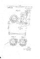
- Figs. 3, 4t and 5 are vertical crosssections of the spool magazines three difierent positions.
- Fig. 6 is a view, partly in horizontal seotion and partly in plan of certain parts of the improved apparatus and Figs. *2 and 8 are sections res lines m-w and 9- 1, of Fig. 1.
- 1 and 2 are two coaxial circular spool mag..- zines mounted so as to be capable of rotating independently of each other; they contain each two sets of spools LII and H17, IV respectively.
- the two sets of spools of each magazine are separated from each other by two partitions 3, Sbetween which a free space is left.
- each ,of the bars 6, 7, is formed on one side with two lower parallel lugs 11 and 12 respectively, and on the other side with two upper parallel lugs 13 and 14 respectively.
- a horizontal pin 15 on a lever 17 fulcrumed on an axle 16 is arranged to enter between the lugs 11 of the bar 7, or the lugs 12 of the bar 6; or a horizontal pin 18 on a lever 20 fulcrumed on the axle 19 is arranged to enter between the lugs 13 of the bar 7 or the lugs 14 of the bar 6.
- 21' is an arm fixed on the axle 16 of lever 17, and 22 is an arm fixed on the axle 19 of lever 20.
- the upper end of rod 10 carries a sliding member 100 in which a plurality of studs 25 equal to the number of the compartments or divisions of the shuttle boxes are slidably mounted. Springs 101 cause these studs to havea constant tendency to slide toward the left.
- Each stud 25 is held in its right hand position by a pawl 25 which is controlled 'by the weft feeler or its magnet, so that the heads of all the studs 25 form a plane in which an antifrict-ion roller 27 on a bellcrank lever 26 can travel without shifting a hookedarm28 which is jointed to lever .20 and is hung l lever 26.
- Thehooked arm 28 is so arranged as to be capable of coming within range of lever 30 that is caused to rock continuously by a revolving cam 29 which is fixed on the lower shaft of the loom and makes one revolution at every second pick.
- a pawl 25 being released by the -electric weft-feeler or its magnet (as here'- .inafter described),'the corresponding stud 25 will be pushed by its spring toward the left, and thus'allow the lever 26 and roller '27 to move likewise toward'the left, so that the hooked arm 28 is let down within range of the rocking lever 30, whereupon the operation of changing of the spool is commenced (provided that no further change of shuttle takes place after the hooked arm 28 has been released and let down), the
- hooked arm is let down without any furth'er action of the weft-feeler, and thus the changing of the spool is started.
- Each spool magazine has two set screws 31, 32 and 33, 34 for which a stationary arm 35 serves as abutment.
- Each bar 6, 7 has a pin 36, 37, adapted to engage stationary guides 38, 39 for the purpose of locking the bars 6, 7.
- a set screw 41 on lever 17, and an abutment 42 on lever 20 serve to limit the movement of these levers relatively to each other,
- Fig. 2 shows the improved spool-changing apparatus in readiness for the insertion of a spool from set III into the corresponding shuttle.
- the weft-feeler has operated to'lower the hooked arm 28 into engagement with the rocking lever 30, and 'the latter has pulled the disengaged lever 20 to the right, and has pulled to the left the lever 17 which has become engaged in the lugs 12.
- the left hand rotation of spool magazine 1 is limited by the screw-31 striking the abutment 35.
- the engagement of pin 37in the looking guide 39 has locked the bar 7 and, through it, also the spool magazine 2; and the partitions 3 of the latter form a guide for the spool that is being ejected from set III. After the ejection of the spool the lever 30 again releases the hooked arm 28,
- Fig. 4 shows the spool magazines rotated to the left by means of bar 7 and lever 17 engaging lugs 11, in. a position of readiness for the e ection of a spool from set I. Magazine 1 is locked by the engagement of pin 36 in guide 38. The ejecting hammer is being guided by partitions 3 of magazine 1. Screw 33 is up against abutment 35.
- Fig. 5 shows the spoolmagazines rotated to the right by means of bar 7 and lever 20 engaging lugs 13, in a position of readiness for the ejection. of a spool from set XI.
- Magazine 1 is locked by the engagement of pin 36 in guide 38.
- the partitions 3 of this magazine serve to guide the ejecting hammer 5.
- Screw 34 is up against abutment 35.
- a weft-replenishing apparatus for an automatic loom worked with more than one shuttle
- the combination with apparatus for changing the shuttles and inserting fresh spools in the shuttles of at least two circular spool magazineslocated coaxially one inside the other and mounted so as to be capable of rotating independently of each other,-each of said magazines being adapted to contain two sets 0 spools, and in each magazine two partitions inclosing a space between them and locatedso'as to separate one set of spools from the other set oi spools in the said magazine, the space between the two partitions in the outer magazine serv- 40 ing as a guide passageway through it for each spool in its ejection from the inner magazine, while the space between the two partitions in the inner magazine serves as a passage-way for the common hammer that saejects the spools from each magazine and inserts them into the shuttles.
- each of said magazines being adapted to contain twosets of spools, and in each magazine two partitions inclosing a space between them and located so as to separate one set of two subscribing witnesses.
- spools from thmhther set of spools in the in the inner magazine serves as a passag may for the common hammer that e ects the spools from each magazine and inserts them into the shuttles, and means for imparting 'lcft and right oscillation to each magazine as required, 'while leaving the other magazine stationary, comprising two bars connected one to each magazine, coupled levers connected to said bars, a continuously rocie ing member, and" rods] controlled by the shuttle-changing apparatus of the loom adapted to engage said bars as required.
- a weft-replenishing apparatus for an automatic loom worked with more than one shuttle
- the combination with apparatus for changing the shuttles and inserting fresh spools in the shuttles of at least two circular spool magazines located coairially one inside the other and mounted so as to be capable of rotating independently of each other, each of said magazines being adapted to contain two sets of spools, and in each magazine two partitions inclosing a space between them and located so as to "separate one set of spools from the other set of 'spools in the said magazine, the space hetween the two partitions in the outer magazine serving as a guide passage-way through it for each spool in its ejection from the inner magazine, while the space between the two partitions in the inner magazine serves as a passageway for the common hammer that,
Description
E. EGLi. WEFT REPLENISHING APPARATUS FOR AUTOMATIC LQOMS WORKED WITH MORE THAN UN APFLICATlON FILED JAN.24I 191? 1,237,316. I Patented Aug. 21,1917
2 SHEETS-SHEET I.
ESHUTTLEK E. EGLI. WEFT REPLENISHING APPARATUS FOR AUTOMATIC TOOMS WORKED WITH MORE TH AN ONE SHUTTLE.
PatentedAug. 21, 1917.
APPLICATION FILED IAN. 24.1917- 2 SHEETSSHEET 2.
UNITED STATES Ar ERNST EGLI, OF RllTI, SWITZERLAND, ASSIGNOR TO MASCHI NENFAIBRIK RT J TI,
FORMERLY GASPAR I-IONEGGER, OF BUTT, SWITZERLAND.
WEFT-REPLENISHICNG APPARATUS To all whom it may concern:
Be it known that I, ERNST EGLI, a citizen of the Republic of Switzerland, residing at tion, such as will enable others skilled in the art to which it appertains to make and use the same, reference being had to the accompanying drawings, and to letters of reference marked thereon, which form a part of this specification.
. It has already been proposed to construct a weft-replenishing apparatus for automatic looms, with two shuttles, a pendulat'ing weft-spool magazine containing two sets of spools of which one set is always in a position of readiness to deliver a fresh spool for replenishing the weft, and a spool-inserting hammer common to both sets of spools. In an apparatus of that kind the spool magazine is arranged to be coupled by means of a rocking lever (fulcrumed on one side of the spool magazine and actuated from the shuttle-box changing apparatus) to a stationary stop when'the said lever is in one position, while when the said lever is in its other position, the said lever is in engagement with a lever under the control of the weft-feeler, and then causes the magazine to swing out and thus allow the spool-in sorting hammer to enter the magazine through an aperture in the side of the latter.
The present invention which is based on the principle embodied in the proposed apparatus above referred to, has, for its object to provide an improved weft-replenishing apparatus which will enable more than two shuttles to be replenished in an automatic loom. With this object, at least two coaxial circular spool magazines mounted so ,as to be capable of rotating independently of each other and each, containing two sets of spools, are provided. The outer spool magazine serves as a guide for the spools during the eiection of a spool from the two I inner sets 0 spools, while theinner magazine leaves a way {Ir-lee: for the insertinghammer to pass thr gh it, when a, spool FOR AUTOMATIC LOOMS 'WORKED WITH MiG RE THZhlid' ONE: SHUTTLE.
Patented. Aug. 21, llfiili'.
, l Application filed January 24, 1917. Serial lilo. 144,265.
is being ejected from the two out-er sets of spools.
Since the path along which each spool that is to be inserted, has to travel before it reaches the position for insertion, is extremely short, the loom is able to work" at a high speed without causing any great vibration of the spool magazines.
The shifting of the spool magazines takes place from a mid-position which is not a position of readiness for inserting'a spool.
The manner in which this invention is to be performed will now be more particularly described with reference to the accompanying drawings which illustrate by way of example a practical construction of apparatus according to this invention.
In these drawings Figures 1 and 2 are diagrammatic side elevations of the improved weft-replcnishing apparatus in two different positions.
Figs. 3, 4t and 5 are vertical crosssections of the spool magazines three difierent positions.
Fig. 6 is a view, partly in horizontal seotion and partly in plan of certain parts of the improved apparatus and Figs. *2 and 8 are sections res lines m-w and 9- 1, of Fig. 1.
In the constructional example shown, 1 and 2 are two coaxial circular spool mag..- zines mounted so as to be capable of rotating independently of each other; they contain each two sets of spools LII and H17, IV respectively. The two sets of spools of each magazine are separated from each other by two partitions 3, Sbetween which a free space is left.
When the two spool magazines 1 and 2 are in their mid-position, that is to say, their position of rest, in which position no spool is being ejected, the free spaces above referred to are situated one over the other (Fig. l),so that the spool-inserting hammer 5 which is actuated in the usual manner from the lay l, is able to the two magazines.
pectively on 6 is a bar jointed to the spool magazine are engaged vbyapin 9 on a red 10 which is moved'up and down themsual. way by the shuttle-changing apparatus. Each ,of the bars 6, 7, is formed on one side with two lower parallel lugs 11 and 12 respectively, and on the other side with two upper parallel lugs 13 and 14 respectively.
According to the position of the bars 6, 7 as to height, a horizontal pin 15 on a lever 17 fulcrumed on an axle 16 is arranged to enter between the lugs 11 of the bar 7, or the lugs 12 of the bar 6; or a horizontal pin 18 on a lever 20 fulcrumed on the axle 19 is arranged to enter between the lugs 13 of the bar 7 or the lugs 14 of the bar 6.
21' is an arm fixed on the axle 16 of lever 17, and 22 is an arm fixed on the axle 19 of lever 20.
These arms 21, 22 are connected by a link 23 so that the rocking of lever 20 entails an oppositely directed rocking oflever 17.
The upper end of rod 10 carries a sliding member 100 in which a plurality of studs 25 equal to the number of the compartments or divisions of the shuttle boxes are slidably mounted. Springs 101 cause these studs to havea constant tendency to slide toward the left. Each stud 25 is held in its right hand position by a pawl 25 which is controlled 'by the weft feeler or its magnet, so that the heads of all the studs 25 form a plane in which an antifrict-ion roller 27 on a bellcrank lever 26 can travel without shifting a hookedarm28 which is jointed to lever .20 and is hung l lever 26.
by means of a spring from Thehooked arm 28 is so arranged as to be capable of coming within range of lever 30 that is caused to rock continuously by a revolving cam 29 which is fixed on the lower shaft of the loom and makes one revolution at every second pick. ,g Now on a pawl 25 being released by the -electric weft-feeler or its magnet (as here'- .inafter described),'the corresponding stud 25 will be pushed by its spring toward the left, and thus'allow the lever 26 and roller '27 to move likewise toward'the left, so that the hooked arm 28 is let down within range of the rocking lever 30, whereupon the operation of changing of the spool is commenced (provided that no further change of shuttle takes place after the hooked arm 28 has been released and let down), the
, hooked arm is let down without any furth'er action of the weft-feeler, and thus the changing of the spool is started.
Thecorresponding released stud 25 which has started the changing of the weft spool, is pushed back each time by an extension 24 of the lever 17, whereupon the said stud is caught again by itspawl 25.
Each spool magazine has two set screws 31, 32 and 33, 34 for which a stationary arm 35 serves as abutment.
Each bar 6, 7 has a pin 36, 37, adapted to engage stationary guides 38, 39 for the purpose of locking the bars 6, 7.
40 is a spring having a constant tendency to pull the lever 20 over to the left (Figs. 1 and 2). A set screw 41 on lever 17, and an abutment 42 on lever 20 serve to limit the movement of these levers relatively to each other,
The operation of the hereinbefore described improved apparatus is as follows In the normal operation of a loom fitted with the improved spool-changing apparatus, the latter is in the position shown in Fig. 1. The free spaces between the partitions 3 of the spool magazines 1 and 2 are situated one over the other; the hammer 5' J the bars 6 and.7, according to the heights at -which the bars 6 and 7 have been set by the shuttle-changing apparatus. According to the said heights of the bars 6 and 7, the pin 36 on bar 6 enters the locking guide 38, or the pin 37 on bar 7 enters the locking guide 39.
Fig. 2 shows the improved spool-changing apparatus in readiness for the insertion of a spool from set III into the corresponding shuttle.
The weft-feeler has operated to'lower the hooked arm 28 into engagement with the rocking lever 30, and 'the latter has pulled the disengaged lever 20 to the right, and has pulled to the left the lever 17 which has become engaged in the lugs 12. The left hand rotation of spool magazine 1 is limited by the screw-31 striking the abutment 35. The engagement of pin 37in the looking guide 39 has locked the bar 7 and, through it, also the spool magazine 2; and the partitions 3 of the latter form a guide for the spool that is being ejected from set III. After the ejection of the spool the lever 30 again releases the hooked arm 28,
and spring 40 pulls the lovers 17 and20, and
set IV. The magazine 2 is locked by the engagement of pin 37 in the guide 89. The spool ejected from set IV is being guided by the partitions 3 of magazine 2. Screw 32 is up against abutment 35.
Fig. 4 shows the spool magazines rotated to the left by means of bar 7 and lever 17 engaging lugs 11, in. a position of readiness for the e ection of a spool from set I. Magazine 1 is locked by the engagement of pin 36 in guide 38. The ejecting hammer is being guided by partitions 3 of magazine 1. Screw 33 is up against abutment 35.
Fig. 5 shows the spoolmagazines rotated to the right by means of bar 7 and lever 20 engaging lugs 13, in a position of readiness for the ejection. of a spool from set XI.
Magazine 1 is locked by the engagement of pin 36 in guide 38. The partitions 3 of this magazine serve to guide the ejecting hammer 5. Screw 34 is up against abutment 35.
It is to be understood that the adjusting movements of the spool magazines are equal in extent for all the adjustments and are comparatively very small, so that no occurrence of injurious 'vibration is to be feared even when the apparatus is working at a high speed.
What I claim is 1. In a weft-replenishing apparatus for an automatic loom worked with more than one shuttle, the combination with apparatus for changing the shuttles and inserting fresh spools in the shuttles, of at least two circular spool magazineslocated coaxially one inside the other and mounted so as to be capable of rotating independently of each other,-each of said magazines being adapted to contain two sets 0 spools, and in each magazine two partitions inclosing a space between them and locatedso'as to separate one set of spools from the other set oi spools in the said magazine, the space between the two partitions in the outer magazine serv- 40 ing as a guide passageway through it for each spool in its ejection from the inner magazine, while the space between the two partitions in the inner magazine serves as a passage-way for the common hammer that saejects the spools from each magazine and inserts them into the shuttles.
2. In a weft-replenislflngapparatus for an automatic loom worked with more than one shuttle, the-combination with apparatus for changing the shuttles and insertin fresh spools in the shuttles, of at least two circular s ool magazines located coaxially one inside.
' t is other and mounted so as to be capable of rotating independently of each other, each of said magazines being adapted to contain twosets of spools, and in each magazine two partitions inclosing a space between them and located so as to separate one set of two subscribing witnesses.
spools from thmhther set of spools in the in the inner magazine serves as a passag may for the common hammer that e ects the spools from each magazine and inserts them into the shuttles, and means for imparting 'lcft and right oscillation to each magazine as required, 'while leaving the other magazine stationary, comprising two bars connected one to each magazine, coupled levers connected to said bars, a continuously rocie ing member, and" rods] controlled by the shuttle-changing apparatus of the loom adapted to engage said bars as required.
3. In a weft-replenishing apparatus for an automatic loom worked with more than one shuttle, the combination with apparatus for changing the shuttles and inserting fresh spools in the shuttles, of at least two circular spool magazines located coairially one inside the other and mounted so as to be capable of rotating independently of each other, each of said magazines being adapted to contain two sets of spools, and in each magazine two partitions inclosing a space between them and located so as to "separate one set of spools from the other set of 'spools in the said magazine, the space hetween the two partitions in the outer magazine serving as a guide passage-way through it for each spool in its ejection from the inner magazine, while the space between the two partitions in the inner magazine serves as a passageway for the common hammer that,
ejects the spools from each magazine and in sorts them into the shuttles, and means for-- preparing and interrupting the changing ofa spool, comprising a'member adapted to be moved by the \veft-feelcr of the loom into position for preparing the changing of the spool. and also adapted to be again moved out of this preparing position by the action of the shuttle-changing apparatus, and further also adapted to be moved afterward hack into the said preparing position with out necessitating the action of the shuttlechanging apparatus.
-In testimony whereof, I have signed my name to this specification in,the presence of ERNST EGLI. Witnesses: v
HERMANN HUBER,
CARL Gunman.
Priority Applications (1)
| Application Number | Priority Date | Filing Date | Title |
|---|---|---|---|
| US14426517A US1237316A (en) | 1917-01-24 | 1917-01-24 | Weft-replenishing apparatus for automatic looms worked with more than one shuttle. |
Applications Claiming Priority (1)
| Application Number | Priority Date | Filing Date | Title |
|---|---|---|---|
| US14426517A US1237316A (en) | 1917-01-24 | 1917-01-24 | Weft-replenishing apparatus for automatic looms worked with more than one shuttle. |
Publications (1)
| Publication Number | Publication Date |
|---|---|
| US1237316A true US1237316A (en) | 1917-08-21 |
Family
ID=3305135
Family Applications (1)
| Application Number | Title | Priority Date | Filing Date |
|---|---|---|---|
| US14426517A Expired - Lifetime US1237316A (en) | 1917-01-24 | 1917-01-24 | Weft-replenishing apparatus for automatic looms worked with more than one shuttle. |
Country Status (1)
| Country | Link |
|---|---|
| US (1) | US1237316A (en) |
Cited By (1)
| Publication number | Priority date | Publication date | Assignee | Title |
|---|---|---|---|---|
| US3101748A (en) * | 1959-09-11 | 1963-08-27 | Rueti Ag Maschf | Multicolor weft replenishing means |
-
1917
- 1917-01-24 US US14426517A patent/US1237316A/en not_active Expired - Lifetime
Cited By (1)
| Publication number | Priority date | Publication date | Assignee | Title |
|---|---|---|---|---|
| US3101748A (en) * | 1959-09-11 | 1963-08-27 | Rueti Ag Maschf | Multicolor weft replenishing means |
Similar Documents
| Publication | Publication Date | Title |
|---|---|---|
| US1237316A (en) | Weft-replenishing apparatus for automatic looms worked with more than one shuttle. | |
| US2221384A (en) | Weft thread feed mechanism | |
| US2140893A (en) | Automatic loom | |
| US1484812A (en) | Weft-replenishing loom | |
| US1703909A (en) | Weft-replenishing mechanism for double-shuttle looms | |
| US1147186A (en) | Multicolor-loom. | |
| US1807722A (en) | S-igjstors to cromptoet | |
| US2062694A (en) | Bobbin release for weft replenishing looms | |
| US2510348A (en) | Bobbin replenishing mechanism for looms | |
| US2149692A (en) | Loom | |
| US1005321A (en) | Holding and releasing device for bobbins in magazines of weft-repleneshing looms. | |
| US1537007A (en) | Shuttle-changing mechanism for looms | |
| US760769A (en) | Filling-replenishing loom. | |
| US810406A (en) | Weft-replenishing mechanism for looms. | |
| US2463904A (en) | Bobbin replenishing mechanism for looms | |
| US2609842A (en) | Device for the insertion of different wefts in weft feeder looms without pirn | |
| US1525773A (en) | Automatic replenishing loom | |
| US1906544A (en) | Filling replenishing mechanism for double shuttle looms | |
| US1510765A (en) | Bobbin-releasing device for looms | |
| US1038888A (en) | Automatic weft-replenishing loom. | |
| US2124979A (en) | Automatic loom | |
| US708672A (en) | Shuttle-guide for weft-replenishing looms. | |
| US1516869A (en) | Weft-thread exchange device for looms | |
| US1602259A (en) | Shuttle magazine for automatic looms | |
| US1133286A (en) | Filling-changer. |