US1237299A - Loaf loading and spacing device. - Google Patents
Loaf loading and spacing device. Download PDFInfo
- Publication number
- US1237299A US1237299A US7247316A US7247316A US1237299A US 1237299 A US1237299 A US 1237299A US 7247316 A US7247316 A US 7247316A US 7247316 A US7247316 A US 7247316A US 1237299 A US1237299 A US 1237299A
- Authority
- US
- United States
- Prior art keywords
- buckets
- spaced
- sides
- loaves
- chutes
- Prior art date
- Legal status (The legal status is an assumption and is not a legal conclusion. Google has not performed a legal analysis and makes no representation as to the accuracy of the status listed.)
- Expired - Lifetime
Links
Images
Classifications
-
- B—PERFORMING OPERATIONS; TRANSPORTING
- B65—CONVEYING; PACKING; STORING; HANDLING THIN OR FILAMENTARY MATERIAL
- B65G—TRANSPORT OR STORAGE DEVICES, e.g. CONVEYORS FOR LOADING OR TIPPING, SHOP CONVEYOR SYSTEMS OR PNEUMATIC TUBE CONVEYORS
- B65G47/00—Article or material-handling devices associated with conveyors; Methods employing such devices
- B65G47/52—Devices for transferring articles or materials between conveyors i.e. discharging or feeding devices
Definitions
- This invention relates to bakery machinery andhasspecial reference to a device to accomplish one step in the automatic preparation and transference of loaves from the dough mixer to the oven.
- a proofer which is a traveling conveyor, made up of a series of buckets of suflicient length to' accommodate about four loaves and in which the loaves must be equally spaced apart. These buckets allow the loaves of dough to properly rise, or as it-is called proof up before molding for the pan and the present invention relates especially to a device for delivering the loaves properly SPZLCGdlIltO these proofer trays.
- One object of the invention is to improve the general construction of devices of this character so that a set,as for instance, four, of loaves maybe deliveredto each proofer tray as it passes thedeliveryportion of the device, the loaves being properly spaced to permit free proofing up.
- a second object of the inventlon' is to provide means which will insure the prevention of interference between successive loaves.
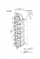
- Figure 1? is a side elevation partly in longitudinal section 'ofa device constructed in accordance with this invention.
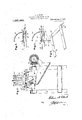
- a Fig. v2 is an enlarged detail section on the line II-II of Fig. 1, certain of theparts beingomitted.
- Fig. 3 is an enlarged detail sectlon on the line III-III of Fig. 2, and showing the swinging side of the bucket in use, dis.- closed as'shut.
- Fig. 4. is a view similar to Fig. 3 but showing the swinging side open.
- Fig. 5 is a detail perspective of certain sliding strips used herewith
- i Fig- 6 is a top planviewof the fingered inner end of the hopper.
- a frame 10 wherein are journaled the axles 11 and 12. Mounted on these axles are sprocket wheels 13 which serve to support spaced. chains 14cv having lugs 14% to which are attached carrying buckets 15 in spaced relation to each other.
- These buckets are divided into sets, the number of buckets in a set being an aliquot part of the total number of buckets; ⁇ For instance, in'the present showing each set ofbuckets is four in number and the buckets number in. all sixteen.
- Each of these buckets is provided with a side 16 hinged to the angle of the bucket as at 17, thesesides or doors being arranged to drop, at proper times between the chains 14.
- these sides are provided with lugs 18 which travel over fixed strips 19 arranged beneath" the upper flights ofthe chainsli, these strips being provided with spaced openings 20 which are normally closed by means of a sliding strip 21 reciprocable in guides 22 on the frame 10, this sliding strip being provided with openings 23 adaptedto be brought to registry with theopenings 20 when the sliding strips 21- are in released position.
- the shaft 11 is driven from any suitable source of power through a counter-shaft 24 and gears 25.
- Onthe'shaft 12 is fixed a cam 26 having a cam groove 27 wherein is carried a cam roller 28 journaled onthe end of a rock arm 29-fixed to a shaft 30 mounted in suitable hearings on the frame 10.
- On the shaft 30 is also fixed a plurality of rock arms 31 pivotally connected to brackets 32 on the sliding strips 21.
- the proportion of the sprocket wheelsand cam is such thatas each set of four-buckets in the present embodiment arrive over respective delivery chutes 33, which are positioned beneath the upper flight of the conveyer, the various openings 23 and will be brought into registry so that the hinged sides 16 of a set may be simultaneously released, thus allowing the loaves carried thereby to drop into the chutes 33 and be delivered to a suitably located proofer tray.
- the chute 34 has a hopper 34: having a series of fingers 33 in the end adjacent the buckets 15.
- an endless conveyer provided with a series of spaced. loaf receiving buckets each having one side hinged, spaced chutes beneath the upper flight of the conveyer, a fixed and movable plate positioned beneath the upper flight for normally holding the sides closed and arranged to release a plurality of the sides simultaneously at predetermined points in their travel;
- an endless conveyer provided with a series of spaced loaf receiving buckets each having a hinged side free to open, spaced chutes beneath the upper flight of the conveyer, means over which the buckets move a predetermined distance holding the sides closed and arranged to release a plurality of the sides simultaneously at predetermined points in their travel and a cam surface over which the sides are adapted to travel to restore the opened sides to closed position upon further travel of the conveyer.
- an endless conveyer provided with a series of spaced loaf receiving buckets each having one side hinged, spaced chutes beneath the upper flight of the conveyer, the upper ends of the chutes being spaced equally with the buckets, and cooperating stationary and movable means normally holding the sides of the loaded buckets closed, the means being free of the buckets and arranged to permit opening of the sides when respective buckets have reached points over respective chutes.
- an endless conveyer provided with a series 35 of spaced loaf receiving buckets each having one side hinged, spaced chutes beneath the upper flight of the conveyer, the upper ends of the chutes being spaced equally with the buckets, cooperating stationary and movable means normally holding the sides of the loaded buckets closed and constituting a track over which the buckets move predetermined distances, the means being provided with mechanism for efiecting an opening of the sides when respective buckets have reached points over respective chutes, and a cam surface over which the sides are adapted to travel to restore the sides to closed position upon further movement of the conveyer.
- an endless conveyer provided with a series of spaced buckets each having a hinged side provided with a laterally projecting lug, a fixed plate over which the lugs travel when the buckets are loaded, the plate being provided with spaced slots with which the lugs may register in sets, a sliding plate having similarly spaced slots movable into and out of registry with the slots in the fixed plate, and means to cause the slots in the two plates to register at predetermined times.
- a track having spaced openings, a shutter slidable therebeneath to open and close the track openings, a series of movably mounted buckets having closure means retained operative by the track and renderedinoperative by the track openings when uncovcred, and a rotary drive for the shutter and the buckets.
- a track having spacedv openings, a slidable shutter for the track openings, meansfor intermittently operating the shutter, a plurality of buckets having closure means operable by the track and rendered inoperative by'the uncovering of the track openings, and means for moving the buckets and operably connected With the first means for operating the latter.
- closure means an endless support for the buckets, a sprocket drive for the support, a track arranged adjacent the support for maintaining the closure means operative and provided With means to permit the closure means to open, and mechanism op- ELMER A. CLARK.
Description
2 SHEETS-SHEET I.
Patented. Aug. 21, 1917.
E- A. CLARK. LOAF LOADING AND SPACING DEVICE. APPUCATION HLED JAN-17,1916.
gm m
E. A. CLARK. LOAF LOADING AND SPAC'NG DEVICE.
APPLICATION FILED J-AN. H, 1916.
Patented Aug. 21, 1917.
2 SHEETS-SHEET 2.
ELMER A. CLARK, OF J'OLIET, ILLINOIS.
LOAF LOADING AND SPACING nnvrcn.
Specification of Letters Patent.
Patented Aug. 21, 1917.
Application filed January 17, 1916. Serial No. 72,473.
To all whom z't'may concern:
Befit known that I, ELMER A. CLARK, a citizen of the United States of America, residing'at Joliet,-in the county of Will and State of'Illinois, have invented certain new and. useful Improvements in Loaf Loading andSpacing Devices, of which the following is a specification. Y
This invention relates to bakery machinery andhasspecial reference to a device to accomplish one step in the automatic preparation and transference of loaves from the dough mixer to the oven.
In apparatus of this description there is used what isknown as a proofer which is a traveling conveyor, made up of a series of buckets of suflicient length to' accommodate about four loaves and in which the loaves must be equally spaced apart. These buckets allow the loaves of dough to properly rise, or as it-is called proof up before molding for the pan and the present invention relates especially to a device for delivering the loaves properly SPZLCGdlIltO these proofer trays. r
1 One object of the invention is to improve the general construction of devices of this character so that a set,as for instance, four, of loaves maybe deliveredto each proofer tray as it passes thedeliveryportion of the device, the loaves being properly spaced to permit free proofing up. A second object of the inventlon' is to provide means which will insure the prevention of interference between successive loaves. g Y With theabove and other objects in wow, thein'vention consists in general ofcertain novel details of construction and combinations of parts hereinafter fully described, illustrated in the accompanying drawings, and specifically claimed.
In the accompanying drawings, like charactersofreference indicate like parts in the several views, and I.
Figure 1? is a side elevation partly in longitudinal section 'ofa device constructed in accordance with this invention. a Fig. v2 is an enlarged detail section on the line II-II of Fig. 1, certain of theparts beingomitted.
Fig. 3 is an enlarged detail sectlon on the line III-III of Fig. 2, and showing the swinging side of the bucket in use, dis.- closed as'shut.
Fig. 4. is a view similar to Fig. 3 but showing the swinging side open.
. Fig. 5 is a detail perspective of certain sliding strips used herewith, and i Fig- 6 is a top planviewof the fingered inner end of the hopper. i In carrying out the objects of the invention, in the present embodiment, therev is provided a frame 10, wherein are journaled the axles 11 and 12. Mounted on these axles are sprocket wheels 13 which serve to support spaced. chains 14cv having lugs 14% to which are attached carrying buckets 15 in spaced relation to each other. These buckets are divided into sets, the number of buckets in a set being an aliquot part of the total number of buckets; {For instance, in'the present showing each set ofbuckets is four in number and the buckets number in. all sixteen. Each of these buckets is provided with a side 16 hinged to the angle of the bucket as at 17, thesesides or doors being arranged to drop, at proper times between the chains 14. Inorder to support'these sides in closed position under loaded con ditions, and before-it is desired to discharge the contentsof the buckets, these sides are provided with lugs 18 which travel over fixed strips 19 arranged beneath" the upper flights ofthe chainsli, these strips being provided with spaced openings 20 which are normally closed by means of a sliding strip 21 reciprocable in guides 22 on the frame 10, this sliding strip being provided with openings 23 adaptedto be brought to registry with theopenings 20 when the sliding strips 21- are in released position. i
The shaft 11 is driven from any suitable source of power through a counter-shaft 24 and gears 25. Onthe'shaft 12 is fixed a cam 26 having a cam groove 27 wherein is carried a cam roller 28 journaled onthe end of a rock arm 29-fixed to a shaft 30 mounted in suitable hearings on the frame 10. On the shaft 30 is also fixed a plurality of rock arms 31 pivotally connected to brackets 32 on the sliding strips 21. The proportion of the sprocket wheelsand cam is such thatas each set of four-buckets in the present embodiment arrive over respective delivery chutes 33, which are positioned beneath the upper flight of the conveyer, the various openings 23 and will be brought into registry so that the hinged sides 16 of a set may be simultaneously released, thus allowing the loaves carried thereby to drop into the chutes 33 and be delivered to a suitably located proofer tray.
I11 order to load the buckets 15, I provide a receiving chute 34L concentric with the shaft 12 and this chute is fed from a suitable divider or weigher which is not here shown as the same does not form part of'this invention. It is obvious that such divider, proofer and loading device are intended to be so geared together as to make the timing of the delivery of the loaves to the chute 34 act in such manner as to permit but one loafto be received by a bucket 15, while the proofer trayswill be timed to arrive at a point. to receive four loaves each from the chutes 33 at the time of delivery of such loaves. The chute 34; has a hopper 34: having a series of fingers 33 in the end adjacent the buckets 15.
In order to restore the sides 16 to closed position, I provide adjacent the sprocket 13 on the shaft 11 a cam member 35 which engages successively with the lugs 18 and raises the sides 16. to closed position, gravity holding these sides when on the lower flight. Each bucket 15 hasa corresponding series of fingers 15 which pass between the hopper fingers 83.v
There has thus been provided a simple and eflicient device of the kind described and for the purpose specified.
It is obvious that many minor changes may be made in the form and construction of the invention without departing from the material principles thereof.
It is not therefore desired to confine the invention to the exact form herein shown and described, but it is wished to include all such as come within the scope claimed.
. Having thus described the invention, what is claimed is 1. In a loading device for proofer trays, an endless conveyer provided with a series of spaced. loaf receiving buckets each having one side hinged, spaced chutes beneath the upper flight of the conveyer, a fixed and movable plate positioned beneath the upper flight for normally holding the sides closed and arranged to release a plurality of the sides simultaneously at predetermined points in their travel;
2. In a loading device for proofer trays,
v an endless conveyer provided with a series of spaced loaf receiving buckets each having a hinged side free to open, spaced chutes beneath the upper flight of the conveyer, means over which the buckets move a predetermined distance holding the sides closed and arranged to release a plurality of the sides simultaneously at predetermined points in their travel and a cam surface over which the sides are adapted to travel to restore the opened sides to closed position upon further travel of the conveyer.
3. In a loading device for proofer trays, an endless conveyer provided with a series of spaced loaf receiving buckets each having one side hinged, spaced chutes beneath the upper flight of the conveyer, the upper ends of the chutes being spaced equally with the buckets, and cooperating stationary and movable means normally holding the sides of the loaded buckets closed, the means being free of the buckets and arranged to permit opening of the sides when respective buckets have reached points over respective chutes.
i. In a loading device for proofer trays, an endless conveyer provided with a series 35 of spaced loaf receiving buckets each having one side hinged, spaced chutes beneath the upper flight of the conveyer, the upper ends of the chutes being spaced equally with the buckets, cooperating stationary and movable means normally holding the sides of the loaded buckets closed and constituting a track over which the buckets move predetermined distances, the means being provided with mechanism for efiecting an opening of the sides when respective buckets have reached points over respective chutes, and a cam surface over which the sides are adapted to travel to restore the sides to closed position upon further movement of the conveyer.
5. Ina loading device, an endless conveyer provided with a series of spaced buckets each having a hinged side provided with a laterally projecting lug, a fixed plate over which the lugs travel when the buckets are loaded, the plate being provided with spaced slots with which the lugs may register in sets, a sliding plate having similarly spaced slots movable into and out of registry with the slots in the fixed plate, and means to cause the slots in the two plates to register at predetermined times. 7
v6. In a device of the class described, a track having spaced openings, a shutter slidable therebeneath to open and close the track openings, a series of movably mounted buckets having closure means retained operative by the track and renderedinoperative by the track openings when uncovcred, and a rotary drive for the shutter and the buckets.
7. In mechanism of the class described, a track having spacedv openings, a slidable shutter for the track openings, meansfor intermittently operating the shutter, a plurality of buckets having closure means operable by the track and rendered inoperative by'the uncovering of the track openings, and means for moving the buckets and operably connected With the first means for operating the latter.
I 8. In mechanism of the class described, a plurality of buckets having unlocked.
closure means, an endless support for the buckets, a sprocket drive for the support, a track arranged adjacent the support for maintaining the closure means operative and provided With means to permit the closure means to open, and mechanism op- ELMER A. CLARK.
Witnesses:
LE0 P. WARD, MARTIN LUNDQUIST.
Copies of this patent may be obtained for five cents each, by addressing the Commissioner of Patents,
Washington, D. C.
Priority Applications (1)
| Application Number | Priority Date | Filing Date | Title |
|---|---|---|---|
| US7247316A US1237299A (en) | 1916-01-17 | 1916-01-17 | Loaf loading and spacing device. |
Applications Claiming Priority (1)
| Application Number | Priority Date | Filing Date | Title |
|---|---|---|---|
| US7247316A US1237299A (en) | 1916-01-17 | 1916-01-17 | Loaf loading and spacing device. |
Publications (1)
| Publication Number | Publication Date |
|---|---|
| US1237299A true US1237299A (en) | 1917-08-21 |
Family
ID=3305118
Family Applications (1)
| Application Number | Title | Priority Date | Filing Date |
|---|---|---|---|
| US7247316A Expired - Lifetime US1237299A (en) | 1916-01-17 | 1916-01-17 | Loaf loading and spacing device. |
Country Status (1)
| Country | Link |
|---|---|
| US (1) | US1237299A (en) |
Cited By (1)
| Publication number | Priority date | Publication date | Assignee | Title |
|---|---|---|---|---|
| US4416299A (en) * | 1981-08-13 | 1983-11-22 | Brandt, Inc. | Coin loader |
-
1916
- 1916-01-17 US US7247316A patent/US1237299A/en not_active Expired - Lifetime
Cited By (1)
| Publication number | Priority date | Publication date | Assignee | Title |
|---|---|---|---|---|
| US4416299A (en) * | 1981-08-13 | 1983-11-22 | Brandt, Inc. | Coin loader |
Similar Documents
| Publication | Publication Date | Title |
|---|---|---|
| US1237299A (en) | Loaf loading and spacing device. | |
| US3538992A (en) | Device for handling discrete laminar articles | |
| US1343184A (en) | Dough-feeding device | |
| US1064194A (en) | Dough-proofing apparatus. | |
| US1763084A (en) | Feeding apparatus for confectionery machines | |
| US760772A (en) | Apparatus for supplying granular material. | |
| US1125804A (en) | Baker's device. | |
| US2684161A (en) | Material counting and stacking apparatus | |
| US945658A (en) | Can-feeding device. | |
| US1827134A (en) | Bakery machinery | |
| US2264674A (en) | Conveyer | |
| US397849A (en) | Ralph i | |
| US1295939A (en) | Machine for roasting peanuts and the like. | |
| US541614A (en) | charles w | |
| US836392A (en) | Grain-elevator. | |
| US1109894A (en) | Apparatus for treating dough preparatory to baking. | |
| US803667A (en) | Conveyer. | |
| US1096509A (en) | Conveyer. | |
| US2847132A (en) | Positive push-off oven unloader | |
| US428916A (en) | Mechanism for measuring- coal | |
| US877963A (en) | Valve-gate and operating means therefor. | |
| US602064A (en) | Conveyer | |
| US1674556A (en) | Hopper | |
| US1657036A (en) | Sorting device for machines for the manufacture of wafers and like articles | |
| US1040826A (en) | Mixing device. |