US1237294A - Extension-table-locking device. - Google Patents
Extension-table-locking device. Download PDFInfo
- Publication number
- US1237294A US1237294A US81193214A US1914811932A US1237294A US 1237294 A US1237294 A US 1237294A US 81193214 A US81193214 A US 81193214A US 1914811932 A US1914811932 A US 1914811932A US 1237294 A US1237294 A US 1237294A
- Authority
- US
- United States
- Prior art keywords
- pedestal
- halves
- fillers
- extension
- lever
- Prior art date
- Legal status (The legal status is an assumption and is not a legal conclusion. Google has not performed a legal analysis and makes no representation as to the accuracy of the status listed.)
- Expired - Lifetime
Links
Images


Classifications
-
- A—HUMAN NECESSITIES
- A47—FURNITURE; DOMESTIC ARTICLES OR APPLIANCES; COFFEE MILLS; SPICE MILLS; SUCTION CLEANERS IN GENERAL
- A47B—TABLES; DESKS; OFFICE FURNITURE; CABINETS; DRAWERS; GENERAL DETAILS OF FURNITURE
- A47B3/00—Folding or stowable tables
- A47B3/02—Folding or stowable tables with foldable cross legs
Definitions
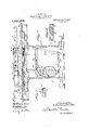
- Figure 1 is a vertical longitudinal section of a table embodying this invention, same being shown at closed position at both the top and supporting member.
- Fig. 2 is a top plan view of the table with a portion of the top broken away to disclose the locking devices, same being shown at locked position of both top and supporting member.
- Fig. 3 is a vertical section showing the top members drawn apart on the supporting member, and the supporting member halves also spread apart, the locking devices being in unlocked position.
- Fig. 4 is a top plan view of the parts in position shown in Fig. 3, the top being broken away to disclose the locking devices.
- Fig. 5 is a section at the line, 55, on Fig. 4.
- Fig. 6 is a section at the line, 66, on Fig. 1.
- Fig. 7 is a section at the line, -77, on Fig. 2, of a lever shown in dotted line on that figure and its engaging member. 1
- Fig. 8 is a section at. the line, 8 8, on Fig. 1.
- Fig. 9 is a detail pedestal connection.
- Fig. 10 is a transverse section of one of the fillers at the position of certain recesses formed for positioning thefillers on the supporting member.
- the table to which this, invention is shown view of a joint in the applied is represented in the common form of pedestal table having two pedestal halves, 1 and 2, adapted to be separated for extension and having the corresponding halves, 3 and 4, of the top member mounted for movement upon the respective pedestal halves for extension of the top with or without opening or spreading the pedestal.
- the usual slides, 5, are shown for connecting the pedestal members with each other and the top member halves with respect to the pedestal halves.
- the pedestal shall be unlocked and its halves spread apart so as to carry thetop halves enough farther apart than they can be spread upon the pedestal to admit thegfillers with their tenons, and then upon closing and locking the pedestal the top halves will be forced together against the intervening fillers and the whole structure securely locked without need of any devices for looking together the top halves, or for locking the top halves to the respective pedestal halves, except as they are retained by the slides extended to the limit permitted by their stops of usual construction.
- the pedestal halves When the table is to be extended to greater length than that provided for in the extensibility of the top members on the pedestal, said top members being first spread apart to that limit, the pedestal halves will be unlocked and drawn apart to admit as many additional fillers as may be desired up to the limit of extensibility of the pedestal.
- the devices for connecting and looking together the pedestal halves are designed for so connecting and locking them when they are completely closed together and at stages of extension corresponding to the width of one or more fillers up to any limit for which the parts are constructed, and these locking devices are adapted for drawing together the pedestal halves to clamp the top members and intervening fillers tightly at each of the several stages of extension for which the pedestal construction is adapted.
- struts or braces for holding the bottom of the pedestal halves at proper distance apart against the operation of the connecting and clamping devices which tend to draw them together, thereby causing the table to be very firmly held in all its parts when the pedestal is extended and blocked as described.
- a latch device comprising a channel bar, 6, which extends from its pivot at 9 on the under side of said first mentioned table top half toward and past the meeting edge, protruding beyond said edge and under the other top half, 4, or fillers which may intervene between the two halves, a distance somewhat more than the width of one less than the number of fillers for which the top halves are arranged to be spread.
- the top halves may be spread on the pedestal to admit three fillers and no more, and that the slide stops will limit their spreading at the three-filler-width position so that means for locking will be necessary only at the closed position, and at the extended positions for accommodating one filler and two fillers, respectively; and the length of the latch device, as illustrated, corresponds to these conditions.
- the latch member, 6, is normally upheld to a position shown in Fig.
- a spring, 10 which conveniently consists of a fiat steel bar having an end rigidly secured to the under side of the table top, 3, and which extends thence along the length of the member, 6, in the channel thereof, (whereby it acts as a guide for its longitudinal movement) and under a cross bar, 6, which extends across the channel at the top a little distance back from the meeting edge of the table top half, 3, and thence on to a point just outside of said meeting edge where said spring is up-bent to form a nose, 10, from the crown of which it slopes ofl' at an angle of easy approach terminating below the plane of the lower surface of the table top.
- This spring by its engagement under the cross bar, 6, of the member, 6, is adapted normally to hold said latch member, 6, up against the under side of the table top; but at this position the nose, 10 projects up past the meeting edge of the top half, 3, and therefore when the table top halves are closed together, or when a filler is interposed between them, the spring is depressed, the crown of its nose being at the lower surface of the table top or filler, and the latch member, 6, is thereby left free to dropdown to a position adapting the devices hereinafter described to engage with the engaging bar hereinafter described, upon the opposite top member, 4.
- a sleeve adapted to slide on the member, 6, a distance equal to the amount of draw which is to be provided for in the device for closing up and cl amping the table top.
- Wlll be suflicient and the parts are proportioned accordmgly.
- the sleeve has a pin,
- the spring 10 which may be provided with an aperture at the foot of the nose, 10, through which the cable is passed, secured by a knot back of the nose.
- a hand lever, 11 This lever is connected by a short link, 11*, with the outer end of the latch bar, X, the pivotal connections of the link being sufficiently free to permit the latch to have its proper upand-down swinging movement for latching and unlatching.
- dle, 11* extended relatively to the pivotal connection, 11 of the link, 11*, so that it swings in a convenient arc of about 60 degrees at the outer side, c. e., toward the end of the table, in swinging the said pivotal connection, 11", from the position at which. the latch bar is thrust to its limit toward the opposite end of the table to a position at which the fulcrum of the lever is between the two pivotal connections of the link.
- the latch, 6, is locked and securely held at top-locking position.
- the aperture, 7 will be engaged, and if two fillers are interposed, the aperture, 7, will be engaged. This will happen before the table top is fully closed up, either with or without the intervening fillers,
- the nose, 10, of the spring,'10 is designed to be of such height and to be so sloped that when either the table top half, 4, or a filler which may be interposed be tween thetwo halves is pushed up toward the table top half, 3, the spring will be readily forced downward and will lower the latch member, 6, and the sleeve, 8, thereon sufliciently for engagement of the tooth, 8 with the proper aperture of the engaging bar, 7, before the edges of the top members are closed together, and that such engagement may be efi'ected while there still remains at least an inch of slac'kof space to be taken up in the top.
- the pedestal halves will be unlocked and spread sufficiently to accommodate the protrusion of the tenons; and the closing and clamping together of the pedestal halves will then close and securely clamp together the top with three intervening fillers.
- the top-lockii-o ing/devices above described are out of served by the maximum extension of thetop halves on the pedestal, and whatever this number, the top-engaging devices need not be arranged to effect the locking of the maximum number when the pedestal is divided and provided with locking devices. If the pedestal is not thus provided, the table top would be arranged for extension enough beyond the number of fillers to be accommodated to admit the tenons, and the innermost aperture in the bar, 7 would, be
- the two slides, 5, attached to one of the pedestal halves (or to the pedestal as a whole if it is not divided) are provided each with a short upwardly-projecting stud, 12, directly under the meeting edges of the two top halves, and each of the fillers is provided in its under side with holes or sockets, 13, positioned at the longitudinal medial line of the filler for receiving these studs, 12; and in direct transverse alinement with these holes at the lateral edges of each filler, there are formed what may be called halfholes or notches, 1&,-14, so that any two abutting fillers have at their meeting edges a socket to accommodate the studs, 12, when the fillers are so positionedas to have their meeting edge at the middle line of the table, at which the studs are located.
- the meeting edges of the table top halves are provided with half-holes, 14,14L, which register when the top halves are closed together and accommodate the studs, 12.
- an Lip-standing lever, 20 upon which there is pivoted at a point intermediate in the height of the pedestal, and preferably a considerable distance below the top, and also a considerable distance from the bottom, a rotatable member, 21, which is also of the nature of a lever.
- This member has its lower end engaged loosely with a bracket, 23, mounted on the pedestal half, 1, and its upper end terminating in a shoulder, 24, for engaging the links of a chain,'A.
- This chain is attached at one end to the opposite pedestal half, 2.
- Its links, 25, are connected by pivot bolts, 26, adapted to be engaged by the shoulder, 2 1, the links being preferably as illustrated in channel form with the side flanges, 25, extended to form the pivot bolts, the web of the channel being deep enough to receive the upper end of the lever, 21, so as to permit the shoulder, 24, to engage the pivot bolts of the chain and to adapt the links to ride upon the upper end of the lever as the chain passes over the latter.
- Said chain, A is adapted to be substantially rigid when extended with the web of the links uppermost,that is, it is prevented from sagging as a flexible chain would normally do,
- the lever, 20, is preferably formed of two bars laid fiatwise upon each other and riveted together at the upper end, but spread apart below and separately fulcrumed at the lower end so as to accommodate between them the member, 21, which is pivoted to said lever between the two bars, the spread of which is sufficient also to afford a free path for the links of the chain, A, as it is engaged with and passes over the upper end of the mem ber, 21.
- the chain, A is designed to be of suflicient length to connect the two pedestal halves at the maximum extension for which the slides connecting said halves are constructed.
- this distance may be understood as four-filler Widths, requiring said connecting chain to be in length about 36 inches, plus the width of the pedestal cavity or distance from the attachment of said chain of one pedestal half to the corner of its engagement with the member, 21, when that member is swung over to its most remote position from the first-mentioned pedestal half.
- said chain such as a common chain loop down below the bracket and extends up to its engagement with the member, 21.
- the means for operating the pedestal locking devices comprise a lever, l5,-17, fulcrumed on the bridge piece or cap of the pedestal half, 1.
- This lever has its handle arm, 15, below and its operating arm, 17, above the cap, 16.
- the operating arm, 17, has a slot, 17 which engages the upper end of the lever, 20.
- each of the links of the chain, A should be equal to or an aliquot part of a filler-width, and should be not less than the movement of the shoulder, 24, derived from the full swing of the lever, 20, so that whatever may be the number of fillers for which the pedestal is extended, such fillers being interposed and the top approximately closed, the shoulder, 24, will findin its path, as the lever, 21, is rocked as described, a link pivot, 26, which needs only to be carried to the limit of the inward movement of the shoulder in order to effect complete closure and clamping of the pedestal at the position, either closed, or partly open corresponding to the number of fillers interposed.
- the movement described will permit the removal of the filler next adjacent to the top half, 3, which will in the same mannerrelease the spring, 10, with the effect above described.
- Thetable may now be further extended, or, thefillersbeing removed, may be closed up, and whether closed up entirely or closed up'upon one or more intervening fillers, can be looked as above described.
- the pedestal halves may now be drawn apart with the effect of swinging the member, 21, and the lever, 20, over toward the pedestal member, 2. In thus extending, it will be noticed that the chain end of the member, 21, which at this position is swung over nearly out of the path of the link pivots, 26.
- the first separating movement above described will have released the end of whatever bottom strut (hereinafter described) may have been in service, which may now be folded up, or if the pedestal is to-be closed up entirely, all the struts may be folded up. Otherwise, the strutto be next used, maybe left down in operative position; and thereupon, any fillers in excess of those which are to be retained in service being first removed, the pedestalhalvesmay be'pushed toward each other.
- the chain at its horizontal portion which extends between the two pedestal halves, is prevented from sagging by the construction described, and this portion is therefore capable of pushing as a stiff member, so that whatever distance the pedestal halves may have been extended and however long the portion of the chain which thus extends horizontally between them, it will be pushed in over the lever, 21, andwill fold down between the separated lower end portions of the lever, 20, hanging as a loop from the bracket, 23, as described.
- the pedestal members are approximately either at closed position or at the desired position for admitting any given number of fillers, such number of fillers being interposed by the operator swinging the lever arm, 17, around to the right, will cause "the shoulder, 24, of the member, 21, to engage the chain pivot, 26, next inward, from it,
- struts or braces 50, 51 and 52, (the drawings being made to show a pedestal adapted to be extended three filler-widths).
- These struts are preferably or conveniently of ⁇ l-shape channel form, or angle-shaped, nested one within another, the outermost strut, 50, (in the order of nesting) being the longest and adapted to space the pedestal halves three filler-widths, the next inner strut, 51, being shorter and of narrower flanges, adapted to space the pedestal halves, two filler-widths, the strut, 52, being still shorter by one filler Width, and correspondingly narrower so that all are nested, the longer and Wider strut, 50, covering the others.
- All the struts are pivoted at the inner end to the foot of the pedestal member, 2, in a position such that they may swing to upright position at one side of the bracket by which the chain, A, is attached, and the opposite pedestal half, 1, has a stop, 55, for lodgment and engagement of the struts, respectively, when they are folded down horizontally for opera tive position.
- I claim 1 In an extension table, in combination with a supporting member, the top halves movable thereon for extension and fillers adapted to be inserted between the extended top halves, the supporting member having studs projecting up at the meeting line of the top halves, the fillers having sockets in their under side at a longitudinal medial line and having half sockets or notches in their edges in direct transverse alinement with the first-mentioned sockets, the top halves having similar half sockets or notches in their meeting edges in direct transverse alinement with the studs.
- a latch device pivoted to the under side of one top half and extending thence across the meeting plane of the two halves; means on the opposite half for engaging said latch device: a yielding device which operates to uphold the latch device out of such engagement, and means by which the yielding device may be depressed extending up above the lower surface of the top so as to be encountered and depressed by the top parts when the top is closed, whereby such closure causes the loop to drop for said engagement.
- a channel-bar latch device pivoted to the under side of one top half; a spring secured to the same top half in a position to extend above the channel of the latch device seats to be depressible thereinto; means extending across the channel under which the spring extends for engagement therewith to uphold the latch device, the spring having a projection which extends upward adjacent to the inner edge of the top member to which the spring is secured in position to be encountered and depressed by the other top member or a filler when the table top is closed, and means on the other top half with which the latch device engages when allowed to drop by the depression of the spring.
- top halves movable thereon for extension and fillers adapted to be interposed; a channel bar latch device pivoted upon one top member having its channel opening upward; a flexible loop member lodged in the channel having its ends connected with the top member to which the latch device is pivoted; means by which one of the ends so connected may be retracted toward the latch pivot, and means ioiifengaging the loop with the other top 5.
- an extension table in combination with a supporting member, top halves movable thereon for extension and fillers adapted to be interposed; a latch device pivoted upon one member and movable longitudinally transversely of the meeting edges of the top halves; a part mounted slidably on the latch device; an engageable member on the opposite top half with which said slidable part is adapted to engage; a flexible loop engaged with said slidable part having one end connected to the latch device and the other end to a fixed point on the same top half which carries the latch device, and means for moving the latch device longitudinally.
- an extension table in combination with a supporting member and top halves movable thereon for extension, a latch device carried on the under side of one top half and extended under the other half, an engageable member on the other half, a loop member carried by the latch device and means for connecting its loop with said engageable member, said loop member having one end connected with the first-mentioned top half and means for retracting the other end.
- an extension table in combination with a supporting member and table-top halves movable on said member for extension, a latch device on one top half and an engageable part on the other half, the latch device being movable longitudinally on the top half 011 which it is mounted; a part movable on the latch device adapted for engag- In testimony whereof, I have hereunto set ing the engageable part on the other top my hand at Chicago, Illinois, this 10th day half, and a flexible loop member attached at of January,'l9l4.
Description
C. S. BURTON.
EXTENSION'TABLE LOCKING DEVICE.
APPLICATION FILED JAN. 14, I914- Patented Aug. 21, 1917.
S'SHEETS-SHEET 1.
C. S. BURTON.
EXTENSION TABLE LOCKING DEVICE.
APPLICATION FILED JAN. 14, I914.
Patented Aw. 21, 1917.
3 SHEETS.SHEE T 2.
C- S. BURTON. EXTENSION TABLE LOCKING DEVICE. APPLICATION men JAN. 14, \914.
n Z mm W5 0 Q a 2 5 m .8 v z 0 ml W t. hm R h a m\ 9 v QESRR .b 4% e E Q a 0 m N V. g \IQN uh. q W N o w? A. 4. R v on @IL M Q\ v x: $5 A M QC R a L L 4 5 2 K I m m. N\.. M 2 9$ m 6 I o 0 o i Q v S b z'aawd CHARLES s. BURTON, or CHICAGO, ILLINOIS.
EXTENSION-TABLE-LOCKING DEVICE.
Specification of Letters Patent. P t nt d Aug. 21, 1917.
Application filed. January 14, 1914. Serial No. 811,932.
and in this respect adapted for so locking together the two halves of a divided pedestal or other form of supporting member when such halves are spread apart for thepurpose of extending the table. It consists in the elements and features of construction shown and described as indicated in the claims.
In the drawings:
Figure 1 is a vertical longitudinal section of a table embodying this invention, same being shown at closed position at both the top and supporting member.
Fig. 2 is a top plan view of the table with a portion of the top broken away to disclose the locking devices, same being shown at locked position of both top and supporting member. l
Fig. 3 is a vertical section showing the top members drawn apart on the supporting member, and the supporting member halves also spread apart, the locking devices being in unlocked position.
Fig. 4 is a top plan view of the parts in position shown in Fig. 3, the top being broken away to disclose the locking devices.
Fig. 5 is a section at the line, 55, on Fig. 4.
Fig. 6 is a section at the line, 66, on Fig. 1.
Fig. 7 is a section at the line, -77, on Fig. 2, of a lever shown in dotted line on that figure and its engaging member. 1
Fig. 8 is a section at. the line, 8 8, on Fig. 1.
Fig. 9 is a detail pedestal connection.
Fig. 10 is a transverse section of one of the fillers at the position of certain recesses formed for positioning thefillers on the supporting member.
The table to which this, invention is shown view of a joint in the applied is represented in the common form of pedestal table having two pedestal halves, 1 and 2, adapted to be separated for extension and having the corresponding halves, 3 and 4, of the top member mounted for movement upon the respective pedestal halves for extension of the top with or without opening or spreading the pedestal. The usual slides, 5, are shown for connecting the pedestal members with each other and the top member halves with respect to the pedestal halves. v 7
It is the common'practice in using tables of this general character,thatis, those having the top halves movable on the pedestal' halves for extension without opening the pedestal, and'adapted for also opening 7 the pedestal for further extension,to eX- tend the table to the limit for which the top halves are movable onthe pedestal halves before taking advantage of the extensibility of the pedestal for further extension of the top, the pedestal being kept closed and locked except when the amountof extension desired is more than that for whichprovision is made in the movability of the top halves upon the pedestal. In accordance with thispractice the provision for locking together the top halves is adapted for so looking themonly at .the several stages of extension lessthan the maximum for which extension is provided without opening the pedestal. At such maximumextension of the top. halves without opening the pedestal, the outward movement ofthe top halves may be understood to be stopped by the usual stops provided in the slides to prevent them from being drawn apart.
When the top halvesare spread to this extent in order to introduce the necessary number of fillers between them and properly engage the sockets and tenons which are customarily provided for properly positioning the fillers with respect to each other and the top. halves, it is intended that the pedestal shall be unlocked and its halves spread apart so as to carry thetop halves enough farther apart than they can be spread upon the pedestal to admit thegfillers with their tenons, and then upon closing and locking the pedestal the top halves will be forced together against the intervening fillers and the whole structure securely locked without need of any devices for looking together the top halves, or for locking the top halves to the respective pedestal halves, except as they are retained by the slides extended to the limit permitted by their stops of usual construction.
When the table is to be extended to greater length than that provided for in the extensibility of the top members on the pedestal, said top members being first spread apart to that limit, the pedestal halves will be unlocked and drawn apart to admit as many additional fillers as may be desired up to the limit of extensibility of the pedestal. The devices for connecting and looking together the pedestal halves are designed for so connecting and locking them when they are completely closed together and at stages of extension corresponding to the width of one or more fillers up to any limit for which the parts are constructed, and these locking devices are adapted for drawing together the pedestal halves to clamp the top members and intervening fillers tightly at each of the several stages of extension for which the pedestal construction is adapted.
The features of the construction shown which are believed to involve novelty and in vention relate to the means provided for connecting the pedestal members adapted for keeping them connected and drawing them toward each other at the several stages of separation suitable for admitting one or more fillers in addition to the fillers which may be admitted by the spreading apart of the top members. Also to the devices for locking together the top member at the stages of extension less than the maximum to which the top members may be spread upon the pedestal members without spreading the latter, and to the means for operating both the pedestal locking and the top locking devices simultaneously by one and the same operating device.
In addition to these features there are shown struts or braces for holding the bottom of the pedestal halves at proper distance apart against the operation of the connecting and clamping devices which tend to draw them together, thereby causing the table to be very firmly held in all its parts when the pedestal is extended and blocked as described.
For the purpose of locking together the two halves of the table there is pivoted upon the table top half, 3, at a considerable distance back from the meeting edge of said halves a latch device comprising a channel bar, 6, which extends from its pivot at 9 on the under side of said first mentioned table top half toward and past the meeting edge, protruding beyond said edge and under the other top half, 4, or fillers which may intervene between the two halves, a distance somewhat more than the width of one less than the number of fillers for which the top halves are arranged to be spread. In the table, as illustrated, it is contemplated that the top halves may be spread on the pedestal to admit three fillers and no more, and that the slide stops will limit their spreading at the three-filler-width position so that means for locking will be necessary only at the closed position, and at the extended positions for accommodating one filler and two fillers, respectively; and the length of the latch device, as illustrated, corresponds to these conditions. The latch member, 6, is normally upheld to a position shown in Fig. 3 by a spring, 10, which conveniently consists of a fiat steel bar having an end rigidly secured to the under side of the table top, 3, and which extends thence along the length of the member, 6, in the channel thereof, (whereby it acts as a guide for its longitudinal movement) and under a cross bar, 6, which extends across the channel at the top a little distance back from the meeting edge of the table top half, 3, and thence on to a point just outside of said meeting edge where said spring is up-bent to form a nose, 10, from the crown of which it slopes ofl' at an angle of easy approach terminating below the plane of the lower surface of the table top. This spring, by its engagement under the cross bar, 6, of the member, 6, is adapted normally to hold said latch member, 6, up against the under side of the table top; but at this position the nose, 10 projects up past the meeting edge of the top half, 3, and therefore when the table top halves are closed together, or when a filler is interposed between them, the spring is depressed, the crown of its nose being at the lower surface of the table top or filler, and the latch member, 6, is thereby left free to dropdown to a position adapting the devices hereinafter described to engage with the engaging bar hereinafter described, upon the opposite top member, 4.
Upon the latch member, 6, there is mounted near the end thereof a sleeve, 8, adapted to slide on the member, 6, a distance equal to the amount of draw which is to be provided for in the device for closing up and cl amping the table top. In the table as illustrated, it is contemplated that one inch draw Wlll be suflicient and the parts are proportioned accordmgly. The sleeve has a pin,
8*, extending through slot, 6 in the bottom of the channel bar, 6, the slot being of suflioient length to permit the sleeve to slide to the extent indicated, and on the pin there is r preferably journaled a pulley, 8*. From the lower side of the sleeve the pin, 8 protrudes downwardly as a tooth, 8 On the under side of the table top half, 4-, there is rigidly mounted an engaging bar, 7, having three apertures, 7, 7 and 7 the first adapted to be engaged by the tooth, 8', at the closed position of the top halves, the second to be similarly engaged when one filler is interposed, and the third to be similarly e11- 6 gaged when two fillers are interposed. Lying within the channel of the channel bar latch member, 6, there is a. flexible connection which may be a cord, chain or wire cable, 19, attached at one end to the channel bar at a distance back from the end on which the sleeve is mounted, the cable or cord extending thence around the pin, 8 and the pulley, 8 thereon, thence back along the channel bar toward the table top member, 3, to which the cable is connected; a convenient means of attaching it is afforded by the spring, 10, which may be provided with an aperture at the foot of the nose, 10, through which the cable is passed, secured by a knot back of the nose.
Upon the under side of the table top member upon which the channel bar, 6, is mounted, there is fulcrumed for swinging horizontally a hand lever, 11. This lever is connected by a short link, 11*, with the outer end of the latch bar, X, the pivotal connections of the link being sufficiently free to permit the latch to have its proper upand-down swinging movement for latching and unlatching. dle, 11*, extended relatively to the pivotal connection, 11 of the link, 11*, so that it swings in a convenient arc of about 60 degrees at the outer side, c. e., toward the end of the table, in swinging the said pivotal connection, 11", from the position at which. the latch bar is thrust to its limit toward the opposite end of the table to a position at which the fulcrum of the lever is between the two pivotal connections of the link. At this position of the lever, the latch, 6, is locked and securely held at top-locking position.
Considering the structure above described, it may be understood that when the table top halves are closed together or are spread with fillers interposed between them, the spring, 10, being depressed will allow the latch bar, 6, to fall and cause the teeth,
8, on the sleeve, 8, to be engaged with one of the apertures of the bar, 7. If the table top halves are not spread apart to admit a filler, the aperture, 7 will be engaged.
If they are spread sufficiently to admit one filler, the aperture, 7 will be engaged, and if two fillers are interposed, the aperture, 7, will be engaged. This will happen before the table top is fully closed up, either with or without the intervening fillers,
that is, while there is yet some slack to be taken up; and it will be seen that upon swinging the lever, 11, around to the locked position described, the latch member, 6, being retracted, will draw the cable, 19, around the pulley, 8*, on the pin, 8*, and pull the sleeve, 8, back toward the table top half, 3, to which the cable is connected, a distance equal to half the retraction of the member,
6, with respect to said top half, 3; and the The lever, 11, has its han-' It will be noticed upon further consideration, that if the two top halves, 3 and 4, instead of being pulled against each other are pulled against an intervening filler fixed with respect to the supporting member of the table, as hereinafter particularly dei, scribed, the two top halves will be crowded against the opposite sides of said intervening fixed part, whichever of said halves comes into contact first with said fixed part being stopped thereby, while the other half continues to move until it also is drawn up against such fixed part; and this is the specific purpose of employing the cable and pulley connection described.
The nose, 10, of the spring,'10, is designed to be of such height and to be so sloped that when either the table top half, 4, or a filler which may be interposed be tween thetwo halves is pushed up toward the table top half, 3, the spring will be readily forced downward and will lower the latch member, 6, and the sleeve, 8, thereon sufliciently for engagement of the tooth, 8 with the proper aperture of the engaging bar, 7, before the edges of the top members are closed together, and that such engagement may be efi'ected while there still remains at least an inch of slac'kof space to be taken up in the top.
As above stated, when the table top halves are separated for admission ofthree fillers, the limit of extension of the slides is reached, and in order to thus interpose the three fillers in view of their projecting tenons, the pedestal halves will be unlocked and spread sufficiently to accommodate the protrusion of the tenons; and the closing and clamping together of the pedestal halves will then close and securely clamp together the top with three intervening fillers. It will be observed that in this last condition, with three intervening fillers, the top-lockii-o ing/devices above described are out of served by the maximum extension of thetop halves on the pedestal, and whatever this number, the top-engaging devices need not be arranged to effect the locking of the maximum number when the pedestal is divided and provided with locking devices. If the pedestal is not thus provided, the table top would be arranged for extension enough beyond the number of fillers to be accommodated to admit the tenons, and the innermost aperture in the bar, 7 would, be
positioned for locking engagement when that number of fillers are interposed.
It isdesirable to provide not only for the clamping and locking together of the top halves with intervening fillers, but when less than a maximum number of fillers are interposed, it is desirable to provide that the total top thus extended shall be positioned symmetrically over the support as when it was closed up without extension, that is, that the extension shall be equal in both directions. This involves the positioning of a single filler with its middle longitudinal line coinciding with the position of the meeting edges of the top halves when they .are closed directly together; and When two fillers are interposed, it involves that the meeting edges of these two fillers should coincide with that line; and when three fillers are interposed, it involves that the middle one shouldbe in the position of the single filler when only one is present. As a simple expedient for accomplishing this, the two slides, 5, attached to one of the pedestal halves (or to the pedestal as a whole if it is not divided) are provided each with a short upwardly-projecting stud, 12, directly under the meeting edges of the two top halves, and each of the fillers is provided in its under side with holes or sockets, 13, positioned at the longitudinal medial line of the filler for receiving these studs, 12; and in direct transverse alinement with these holes at the lateral edges of each filler, there are formed what may be called halfholes or notches, 1&,-14, so that any two abutting fillers have at their meeting edges a socket to accommodate the studs, 12, when the fillers are so positionedas to have their meeting edge at the middle line of the table, at which the studs are located. Similarly the meeting edges of the table top halves are provided with half-holes, 14,14L, which register when the top halves are closed together and accommodate the studs, 12. With this construction, it will be seen that when the table is spread for admission of one filler, such filler being lodged upon the slides at the middle point, will be engaged by the studs entering the holes, 13, of the filler, and thereby be held positively against movement either away from the middle of the table, or that if two fillers are interposed, their meeting edges will be positioned at the middle line of the table by abutting against opposite sides of the studs which enter the halfholes in each; also that when three fillers are interposed the middle one being positioned and engaged with the studs, 12, in the same manner as if it were the only one, will positively position the other two at opposite sides of it.
'The pedestal locking device will now be described. Upon the pedestal half, 1, there is fulcrumed, preferably as near the bottom as convenient, an Lip-standing lever, 20, upon which there is pivoted at a point intermediate in the height of the pedestal, and preferably a considerable distance below the top, and also a considerable distance from the bottom, a rotatable member, 21, which is also of the nature of a lever. This member has its lower end engaged loosely with a bracket, 23, mounted on the pedestal half, 1, and its upper end terminating in a shoulder, 24, for engaging the links of a chain,'A. This chain is attached at one end to the opposite pedestal half, 2. Its links, 25, are connected by pivot bolts, 26, adapted to be engaged by the shoulder, 2 1, the links being preferably as illustrated in channel form with the side flanges, 25, extended to form the pivot bolts, the web of the channel being deep enough to receive the upper end of the lever, 21, so as to permit the shoulder, 24, to engage the pivot bolts of the chain and to adapt the links to ride upon the upper end of the lever as the chain passes over the latter. Said chain, A, is adapted to be substantially rigid when extended with the web of the links uppermost,that is, it is prevented from sagging as a flexible chain would normally do,
by the formation of the links .at their abutting ends, With shoulders, 25", including the end of the web of the channel and posi-.
tionecl in planes at right angles to the length of the link diametric with respect to the pivot of the links to each other. The lever, 20, is preferably formed of two bars laid fiatwise upon each other and riveted together at the upper end, but spread apart below and separately fulcrumed at the lower end so as to accommodate between them the member, 21, which is pivoted to said lever between the two bars, the spread of which is sufficient also to afford a free path for the links of the chain, A, as it is engaged with and passes over the upper end of the mem ber, 21. The chain, A, is designed to be of suflicient length to connect the two pedestal halves at the maximum extension for which the slides connecting said halves are constructed. As illustrated, this distance may be understood as four-filler Widths, requiring said connecting chain to be in length about 36 inches, plus the width of the pedestal cavity or distance from the attachment of said chain of one pedestal half to the corner of its engagement with the member, 21, when that member is swung over to its most remote position from the first-mentioned pedestal half. In order to accommodate this length within the height of the pedestal when the pedestal halves are closed together and the length is not taken up in extending across the distance which they are spread a art said chain such as a common chain loop down below the bracket and extends up to its engagement with the member, 21.
The means for operating the pedestal locking devices comprise a lever, l5,-17, fulcrumed on the bridge piece or cap of the pedestal half, 1. This lever has its handle arm, 15, below and its operating arm, 17, above the cap, 16. The operating arm, 17, has a slot, 17 which engages the upper end of the lever, 20. When the lever, 15, 17, is moved to carry the said upper end of the lever, 20, in toward the end of the pedestal member on which it is mountedthat is, away from the parting plane of the two pedestal membersthe member, 21, is rocked over its engagement with the bracket, 23, and its upper end is carried in the same direction as the lever, 20, but substantially twice as far as the pivot of the lever, 21, to the lever, 20, is carried by the same swinging movement of said lever, 20. In this movement of the lever, 21, its shoulder, 24, encounters and engages one of the pivots of the chain, 26, and draws the latter with it, thereby drawing the two pedestal halves together when the lever arm, 15, reaches its limit of swinging and is locked by engagement with the ratchet tooth, 18, on the plate, 18. The length of each of the links of the chain, A,that is, the distance from pivot to pivot, should be equal to or an aliquot part of a filler-width, and should be not less than the movement of the shoulder, 24, derived from the full swing of the lever, 20, so that whatever may be the number of fillers for which the pedestal is extended, such fillers being interposed and the top approximately closed, the shoulder, 24, will findin its path, as the lever, 21, is rocked as described, a link pivot, 26, which needs only to be carried to the limit of the inward movement of the shoulder in order to effect complete closure and clamping of the pedestal at the position, either closed, or partly open corresponding to the number of fillers interposed. Usually the amount of slack to be taken up by the action described will be very much less than the link length, so that the shoulder, 24, will not encountera link pivot until it has traversed a considerable portion of its path toward the locking position, and in the last portion only of that path when it encounters the pivot, will it operate for drawing upon the pedestal members.
For unlocking the top, either to open it up to receive fillers or to remove fillers preparatory to closing it up, the operator will swing the handle of the lever, 11, around to the full line position in Fig. 4. In this movement, said lever, 11, will move the latch member, 6, outward,that is, toward the table-top half opposite that on which said latch member is carried, and will thereby slacken the engagementof the top-locking devices, The operator may now draw the will ride freely over the outwardly leaning top halves apart sufliciently to disengage them from each other or from the intervening fillers. If the table has been closed up without fillers, this separation will release the spring 10, and cause it to operate to lift the latch device, disengaging its member, 8, from the bar, 7. If the table has been extended, the movement described will permit the removal of the filler next adjacent to the top half, 3, which will in the same mannerrelease the spring, 10, with the effect above described. Thetable may now be further extended, or, thefillersbeing removed, may be closed up, and whether closed up entirely or closed up'upon one or more intervening fillers, can be looked as above described.
If the pedestal is to be either opened or closed up, the operator will first disengage the lever arm, 17, from the shoulder, 18
of the bar, 18. The pedestal halves may now be drawn apart with the effect of swinging the member, 21, and the lever, 20, over toward the pedestal member, 2. In thus extending, it will be noticed that the chain end of the member, 21, which at this position is swung over nearly out of the path of the link pivots, 26. The first separating movement above described will have released the end of whatever bottom strut (hereinafter described) may have been in service, which may now be folded up, or if the pedestal is to-be closed up entirely, all the struts may be folded up. Otherwise, the strutto be next used, maybe left down in operative position; and thereupon, any fillers in excess of those which are to be retained in service being first removed, the pedestalhalvesmay be'pushed toward each other. In thus closing up the pedestal, the chain at its horizontal portion which extends between the two pedestal halves, is prevented from sagging by the construction described, and this portion is therefore capable of pushing as a stiff member, so that whatever distance the pedestal halves may have been extended and however long the portion of the chain which thus extends horizontally between them, it will be pushed in over the lever, 21, andwill fold down between the separated lower end portions of the lever, 20, hanging as a loop from the bracket, 23, as described. When the pedestal members are approximately either at closed position or at the desired position for admitting any given number of fillers, such number of fillers being interposed by the operator swinging the lever arm, 17, around to the right, will cause "the shoulder, 24, of the member, 21, to engage the chain pivot, 26, next inward, from it,
and draw the pedestal halves toward each ing the appropriate number of fillers when the lever arm, 17, has completed its swinging and become engaged with the ratchet tooth, 18 so that the table, both as to pedestal and top, will at this stage be rigidly locked so as tobe rigid from top to bottom.
For spacing the pedestal halves at the bottom, suitably for the desired number of fillers up to the maximum number for which it can be extended, there are provided struts or braces, 50, 51 and 52, (the drawings being made to show a pedestal adapted to be extended three filler-widths). These struts are preferably or conveniently of \l-shape channel form, or angle-shaped, nested one within another, the outermost strut, 50, (in the order of nesting) being the longest and adapted to space the pedestal halves three filler-widths, the next inner strut, 51, being shorter and of narrower flanges, adapted to space the pedestal halves, two filler-widths, the strut, 52, being still shorter by one filler Width, and correspondingly narrower so that all are nested, the longer and Wider strut, 50, covering the others. All the struts are pivoted at the inner end to the foot of the pedestal member, 2, in a position such that they may swing to upright position at one side of the bracket by which the chain, A, is attached, and the opposite pedestal half, 1, has a stop, 55, for lodgment and engagement of the struts, respectively, when they are folded down horizontally for opera tive position.
I claim 1. In an extension table, in combination with a supporting member, the top halves movable thereon for extension and fillers adapted to be inserted between the extended top halves, the supporting member having studs projecting up at the meeting line of the top halves, the fillers having sockets in their under side at a longitudinal medial line and having half sockets or notches in their edges in direct transverse alinement with the first-mentioned sockets, the top halves having similar half sockets or notches in their meeting edges in direct transverse alinement with the studs.
2. In an extension table, in combination with a supporting member and top halves movable thereon for extension, a latch device pivoted to the under side of one top half and extending thence across the meeting plane of the two halves; means on the opposite half for engaging said latch device: a yielding device which operates to uphold the latch device out of such engagement, and means by which the yielding device may be depressed extending up above the lower surface of the top so as to be encountered and depressed by the top parts when the top is closed, whereby such closure causes the loop to drop for said engagement.
3. In an extension table, in combination with top halves movable toward andv from each other for extension; a channel-bar latch device pivoted to the under side of one top half; a spring secured to the same top half in a position to extend above the channel of the latch device seats to be depressible thereinto; means extending across the channel under which the spring extends for engagement therewith to uphold the latch device, the spring having a projection which extends upward adjacent to the inner edge of the top member to which the spring is secured in position to be encountered and depressed by the other top member or a filler when the table top is closed, and means on the other top half with which the latch device engages when allowed to drop by the depression of the spring.
4. In an extension table, in combination with a supporting member, top halves movable thereon for extension and fillers adapted to be interposed; a channel bar latch device pivoted upon one top member having its channel opening upward; a flexible loop member lodged in the channel having its ends connected with the top member to which the latch device is pivoted; means by which one of the ends so connected may be retracted toward the latch pivot, and means ioiifengaging the loop with the other top 5. In an extension table, in combination with a supporting member, top halves movable thereon for extension and fillers adapted to be interposed; a latch device pivoted upon one member and movable longitudinally transversely of the meeting edges of the top halves; a part mounted slidably on the latch device; an engageable member on the opposite top half with which said slidable part is adapted to engage; a flexible loop engaged with said slidable part having one end connected to the latch device and the other end to a fixed point on the same top half which carries the latch device, and means for moving the latch device longitudinally.
6. In an extension table, in combination with a supporting member and top halves movable thereon for extension, a latch device carried on the under side of one top half and extended under the other half, an engageable member on the other half, a loop member carried by the latch device and means for connecting its loop with said engageable member, said loop member having one end connected with the first-mentioned top half and means for retracting the other end.
7. In an extension table, in combination with a supporting member and table-top halves movable on said member for extension, a latch device on one top half and an engageable part on the other half, the latch device being movable longitudinally on the top half 011 which it is mounted; a part movable on the latch device adapted for engag- In testimony whereof, I have hereunto set ing the engageable part on the other top my hand at Chicago, Illinois, this 10th day half, and a flexible loop member attached at of January,'l9l4.
one end to the loop and at the other end to CHARLES S. BURTON. 1 the first-mentioned top half and having its Witnesses:
100p engaged With said part movable on the EDNA M. MAoINTosH,
latch device. M. GERTRUDE ADY.
Copies of this patent may be obtained for five cents each, by addressingthe Commissioner of Patents, Washington, D. G.
Priority Applications (1)
| Application Number | Priority Date | Filing Date | Title |
|---|---|---|---|
| US81193214A US1237294A (en) | 1914-01-14 | 1914-01-14 | Extension-table-locking device. |
Applications Claiming Priority (1)
| Application Number | Priority Date | Filing Date | Title |
|---|---|---|---|
| US81193214A US1237294A (en) | 1914-01-14 | 1914-01-14 | Extension-table-locking device. |
Publications (1)
| Publication Number | Publication Date |
|---|---|
| US1237294A true US1237294A (en) | 1917-08-21 |
Family
ID=3305113
Family Applications (1)
| Application Number | Title | Priority Date | Filing Date |
|---|---|---|---|
| US81193214A Expired - Lifetime US1237294A (en) | 1914-01-14 | 1914-01-14 | Extension-table-locking device. |
Country Status (1)
| Country | Link |
|---|---|
| US (1) | US1237294A (en) |
-
1914
- 1914-01-14 US US81193214A patent/US1237294A/en not_active Expired - Lifetime
Similar Documents
| Publication | Publication Date | Title |
|---|---|---|
| US606845A (en) | Folding table | |
| US1237294A (en) | Extension-table-locking device. | |
| KR20200002935A (en) | Collapsible articulated structure to support the seat or support surface | |
| US567491A (en) | Extensible carriage-seat | |
| US1003780A (en) | Swinging cot. | |
| US1737821A (en) | Folding table | |
| US540794A (en) | Folding chair | |
| US390173A (en) | jones | |
| US729291A (en) | Tripod. | |
| US576636A (en) | Camp-stool | |
| US963502A (en) | Foldable table. | |
| US2226000A (en) | Collapsible carriage | |
| US360556A (en) | Folding crib | |
| US232100A (en) | Folding ironing-table | |
| US957637A (en) | Extension-table. | |
| US1151733A (en) | Extension-table. | |
| US1004220A (en) | Extension-table. | |
| US574916A (en) | Extension car-step | |
| US1558087A (en) | Folding bench and table | |
| US1056745A (en) | Car-step. | |
| US699265A (en) | Garment-supporter. | |
| US298430A (en) | Oelando a | |
| US1092698A (en) | Adjustable support for beds. | |
| US1081272A (en) | Bed-davenport. | |
| US939379A (en) | Extension-table lock. |