US1237274A - Antiskidding device. - Google Patents
Antiskidding device. Download PDFInfo
- Publication number
- US1237274A US1237274A US72573512A US1912725735A US1237274A US 1237274 A US1237274 A US 1237274A US 72573512 A US72573512 A US 72573512A US 1912725735 A US1912725735 A US 1912725735A US 1237274 A US1237274 A US 1237274A
- Authority
- US
- United States
- Prior art keywords
- chains
- hook
- tire
- hooks
- members
- Prior art date
- Legal status (The legal status is an assumption and is not a legal conclusion. Google has not performed a legal analysis and makes no representation as to the accuracy of the status listed.)
- Expired - Lifetime
Links
Images
Classifications
-
- B—PERFORMING OPERATIONS; TRANSPORTING
- B60—VEHICLES IN GENERAL
- B60C—VEHICLE TYRES; TYRE INFLATION; TYRE CHANGING; CONNECTING VALVES TO INFLATABLE ELASTIC BODIES IN GENERAL; DEVICES OR ARRANGEMENTS RELATED TO TYRES
- B60C27/00—Non-skid devices temporarily attachable to resilient tyres or resiliently-tyred wheels
- B60C27/02—Non-skid devices temporarily attachable to resilient tyres or resiliently-tyred wheels extending over restricted arcuate part of tread
- B60C27/04—Non-skid devices temporarily attachable to resilient tyres or resiliently-tyred wheels extending over restricted arcuate part of tread the ground-engaging part being rigid
Definitions
- This invention relates to an' improvement' in anti-skidding devices designed more particularly for resilient tires.
- cepted type is what is now' commonly termed the Weed chain wherein two chain members are employed, one to be located on each side of the .rim or tire, cross over chains being placed at distances apart for connecting the two side chains.
- the resent 1nvent1on comprehends' the utilization of the principle ofthe Weed chain but the elimination of the necessity of having the connecting the body side of the wheel.
- the invention comprises broadly the employment of a substantially rigid hook member designed and proportioned to embrace the tire with its free or bill end extended inward to a point sufi'iciently beyond the plane of the center of the tire to maintain the hook on the .tire against accidental skewing or twisting 01f.
- a substantially rigid hook member designed and proportioned to embrace the tire with its free or bill end extended inward to a point sufi'iciently beyond the plane of the center of the tire to maintain the hook on the .tire against accidental skewing or twisting 01f.
- Figure v1 15 aside elevation of a portion of a wheel with the anti-skidding device ppl Fig.- 2 1s a top plan showing the cross over member,
- Fig. 3 is a section through the wheel showing the cross over member in elevation
- Fig. 4 1s a perspective view of the cross over member
- i Fig. 5 is a detail of the connecting means between the chains.
- A designates the tire mounted on the wheel B in any approved form.
- the tire is shown in this application as being of the pneumatic type. The invention, however, is
- C, D represent two chain members varying in length, the inner member being of a 1% length than These chains are artially parallel relation and will be maintained 1n that position by the cross over L, members E.
- cross over members E are shown as formed of substantially rigid metal conveniently in the form of cylindrical bars of a diameter or gage approximating a quarter of an inch, more or less and the sameis bent into double hooked form, the parallel portions of which are separated and carried down on the chain side ofthe device where they terminate in shank portions, the ends of which are looped as at e, c, the former being located at a'plane beyond the latter.
- An anti-skidding device for resilienttires comprising a series of substantially rigid hook members shaped to embrace the sides of a tire, each hook having a shank portion arranged to occupy a position at the same side of the wheel, a plurality of chains each of which is attached to a-shank of ahook the point of attachment of the respective chains being spaced apart longitudinally of the shank, and means for connecting the ends of the chains.
- An antiskid device for wheels having resilient tires comprising a plurality of rigid hook members having their hook portions shaped to embrace the tire with the end of the hook projecting inwardly beyond the tire, and a shank portion, of a plurality of chain members extending from hook to hook and connected with the shanks of the hooks, one of said chain members being positioned nearer the ends of the shanks of the hooks than the other, and means for connecting 3 the ends of the chains.
Description
L. s. BACON. ANTISKIDDING DEVICE. APPLICATION FILED OCT. 14. 1912.
V avw'emtoz: [92)! (PM M M attowm3&-
- Patented Aug To all whom it may concern.
LEVI snwm BACON, or wnsrimo'ron', nrs'mrc'r or conumnm.
mismnnme nnvrcn.
Be it known that I, LEVI SEWARD BACON, a citizen of the United States, residing at Washington, in the District of Columbia, have invented certain new and useful Improvements. in Antiskidding Devices, of which the following is a specification, reference being had therein to the accompanying drawing.
This invention relates to an' improvement' in anti-skidding devices designed more particularly for resilient tires. The invention has to do more particularly with that type of anti-skidding devices wherein a series of metallic members are projected across the tread of the tire, the members being retained in place suitable means, the con-= struction permitting the removal and rreplacement of'tlie device at the willof'the user. cepted type is what is now' commonly termed the Weed chain wherein two chain members are employed, one to be located on each side of the .rim or tire, cross over chains being placed at distances apart for connecting the two side chains.
The resent 1nvent1on comprehends' the utilization of the principle ofthe Weed chain but the elimination of the necessity of having the connecting the body side of the wheel.
The invention comprises broadly the employment of a substantially rigid hook member designed and proportioned to embrace the tire with its free or bill end extended inward to a point sufi'iciently beyond the plane of the center of the tire to maintain the hook on the .tire against accidental skewing or twisting 01f. I have found that in the application of the hook to the chain type of anti-skidding devices it is convenientto employ a plurality of chains, one arranged within the other and each of which is provided with a connection with a difierent part of the hook or cross over member.
- By employing a plurality of chains, conveniently two, the hooks are provided with two points of anchor or connection and therefore twisting or turning is materially resisted. t
A form of anti-sln'dding device is shown in the accompanying drawings embodying an exceedingly simple construction, but it is to he understood that 'various modifications and changes can be made without de- Specification of Letters Patent.
Heretofore generally the more a'cthe outer mem'ber. ranged so that they will assume substanchain located on- I Patented Aug. .21 1917.
Applicationfiled octoberi4,1912. Serial No..725,7 3-5.
parting from the nature and principle of the invention.
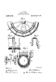
In the drawings: Figure v1 15 aside elevation of a portion of a wheel with the anti-skidding device ppl Fig.- 2 1s a top plan showing the cross over member,
Fig. 3 is a section through the wheel showing the cross over member in elevation, Fig. 4 1s a perspective view of the cross over member, and i Fig. 5 is a detail of the connecting means between the chains.
A designates the tire mounted on the wheel B in any approved form. The tire is shown in this application as being of the pneumatic type. The invention, however, is
not necessarily limited in its useful application to that type of tire. C, D, represent two chain members varying in length, the inner member being of a 1% length than These chains are artially parallel relation and will be maintained 1n that position by the cross over L, members E. For convenience of illustration and as a practical embodiment of the invention, cross over members E are shown as formed of substantially rigid metal conveniently in the form of cylindrical bars of a diameter or gage approximating a quarter of an inch, more or less and the sameis bent into double hooked form, the parallel portions of which are separated and carried down on the chain side ofthe device where they terminate in shank portions, the ends of which are looped as at e, c, the former being located at a'plane beyond the latter. This is efi'ectedby making one of the shanks of the hook longer than its companion shank. The loops e, e are connected respectively to links of the chains, as shown and as in. the type of devices heretofore used when the hook becomes worn it is only necessary to open the loops, remove the same from the links, replacing the hooks by new ones and closing the eyes or loops over the links. This replacement can be elfected by the user without material trouble or expense. The spread of the hook between the bill and the shank portions is suificiently great to permit the hook to be easily passed over the tire withthe bill E carried down to a point approximating the plane of the loop a. I By this arrangement both the loop e and the end of the hook arecarried well tion being shown in Fig. 5, two cross bars] inaeaave chan es in the torm'and arrangement-with out departing from the nature and spirit thereof.
Having thus what is claimed as new anddesired to secured by Letters Patent is: '1. Ananti-skidding device for wheels described the invention,
F, F having their ends looped through the having resilient tires comprisin a series of end links of the respective chains C, D, and are provided centrally with seats or apertures 7 through which suitable links f are passed. Pivotally connected with the f is one member of a lever fastener and this fastener G has pivotally connected thereto a hooked lever g. It is to be under stood that the fastener is shown somewhat diagrammatically and that any now well known or approved form of lover or other fastener may be employed. By having the cross bars f the tension on the two chains C, D is equalized properly although in this connection the invention is not hmited to the application of asingle fastener for the two chains, as pivotally independent fasteners can be employed if necessary. In applying the device it is only necessary to.
- slip the hooks over the tire, stretching the chains so'that the hooks will be in substantially proper position, and then connect the ends of the chains in any well known manner. By putting tension on the chains the hooks are held properly in their position, but at the same time the entire anti-skidding device will'be permitted a slight creeping action around the rubber tire or shoe. Among the advantages of the construction shown is that of application without the necessity of moving the wheel, the avoidance of danger of the device becoming unfastened and falling into the running gear. By the loop construction of the shank parts E and E, worn hooks can be removed and new hooks'applied withbut little trouble and expense and the device is compact and can be readily stored in the vehicle body.v
It willwbe observed that by employing a substantially ri "id hook, and by the term rigid it will e understood that the book should be of that character wherein springing or bending of the same outward is not necessary for application, a very complete anti-ski ding device is produced, one having a large amount of traction surface. It is to be understood that the invention is susceptible of many modifications and a and means for connecting the r ends of the chain members.
2. An anti-skidding device for resilienttires [comprising a series of substantially rigid hook members shaped to embrace the sides of a tire, each hook having a shank portion arranged to occupy a position at the same side of the wheel, a plurality of chains each of which is attached to a-shank of ahook the point of attachment of the respective chains being spaced apart longitudinally of the shank, and means for connecting the ends of the chains.
3. An antiskid device for wheels having resilient tires comprising a plurality of rigid hook members having their hook portions shaped to embrace the tire with the end of the hook projecting inwardly beyond the tire, and a shank portion, of a plurality of chain members extending from hook to hook and connected with the shanks of the hooks, one of said chain members being positioned nearer the ends of the shanks of the hooks than the other, and means for connecting 3 the ends of the chains.
LEVI SEWARD BACON.
Witnesses:
GERTRUDE WEDEMELER, Jae. E. HUTGHINSON.
Priority Applications (1)
| Application Number | Priority Date | Filing Date | Title |
|---|---|---|---|
| US72573512A US1237274A (en) | 1912-10-14 | 1912-10-14 | Antiskidding device. |
Applications Claiming Priority (1)
| Application Number | Priority Date | Filing Date | Title |
|---|---|---|---|
| US72573512A US1237274A (en) | 1912-10-14 | 1912-10-14 | Antiskidding device. |
Publications (1)
| Publication Number | Publication Date |
|---|---|
| US1237274A true US1237274A (en) | 1917-08-21 |
Family
ID=3305093
Family Applications (1)
| Application Number | Title | Priority Date | Filing Date |
|---|---|---|---|
| US72573512A Expired - Lifetime US1237274A (en) | 1912-10-14 | 1912-10-14 | Antiskidding device. |
Country Status (1)
| Country | Link |
|---|---|
| US (1) | US1237274A (en) |
Cited By (3)
| Publication number | Priority date | Publication date | Assignee | Title |
|---|---|---|---|---|
| US2596248A (en) * | 1946-08-17 | 1952-05-13 | James A Kennedy | Vehicle driving chain |
| US2598298A (en) * | 1949-03-31 | 1952-05-27 | Leo J Pindjak | Antiskid device for vehicle tires |
| US6543501B2 (en) * | 2001-08-09 | 2003-04-08 | John A. Ferreira | Traction assembly for vehicles |
-
1912
- 1912-10-14 US US72573512A patent/US1237274A/en not_active Expired - Lifetime
Cited By (3)
| Publication number | Priority date | Publication date | Assignee | Title |
|---|---|---|---|---|
| US2596248A (en) * | 1946-08-17 | 1952-05-13 | James A Kennedy | Vehicle driving chain |
| US2598298A (en) * | 1949-03-31 | 1952-05-27 | Leo J Pindjak | Antiskid device for vehicle tires |
| US6543501B2 (en) * | 2001-08-09 | 2003-04-08 | John A. Ferreira | Traction assembly for vehicles |
Similar Documents
| Publication | Publication Date | Title |
|---|---|---|
| US1237274A (en) | Antiskidding device. | |
| US2310467A (en) | Antiskid appliance | |
| US1190816A (en) | Antiskidding device. | |
| US1504416A (en) | Emergency chain for nonskid tire chains | |
| US1293424A (en) | Antiskidding device. | |
| US870657A (en) | Traction attachment for vehicle-tires. | |
| US1326513A (en) | Antiskid-chain. | |
| US1493878A (en) | Antiskid chain | |
| US969425A (en) | Antiskidding device for wheel-tires. | |
| US1333873A (en) | Antiskidding device | |
| US1259190A (en) | Antiskid device for vehicle-wheels. | |
| US1273933A (en) | Antiskid device for vehicle-wheels. | |
| US1335165A (en) | Equalizing-retainer for tire-chains | |
| US995372A (en) | Tire-chain. | |
| US1017909A (en) | Traction and non-skid device. | |
| US1419680A (en) | Antiskidding device | |
| US1552434A (en) | Antiskid device | |
| US1553620A (en) | Nonskid mechanism | |
| US1244080A (en) | Non-skid tire-protector. | |
| US978210A (en) | Tire-tread attachment. | |
| US1388748A (en) | Tire-protector | |
| US1315366A (en) | herman | |
| US991013A (en) | Grip-tread for vehicle-tires. | |
| US1523135A (en) | Nonskid device for vehicle wheels | |
| US1298924A (en) | Traction-tread. |