US1237256A - Yarn-feeding device for knitting-machines. - Google Patents
Yarn-feeding device for knitting-machines. Download PDFInfo
- Publication number
- US1237256A US1237256A US6642615A US6642615A US1237256A US 1237256 A US1237256 A US 1237256A US 6642615 A US6642615 A US 6642615A US 6642615 A US6642615 A US 6642615A US 1237256 A US1237256 A US 1237256A
- Authority
- US
- United States
- Prior art keywords
- yarn
- needles
- guide
- dial
- plate
- Prior art date
- Legal status (The legal status is an assumption and is not a legal conclusion. Google has not performed a legal analysis and makes no representation as to the accuracy of the status listed.)
- Expired - Lifetime
Links
Images

Classifications
-
- D—TEXTILES; PAPER
- D04—BRAIDING; LACE-MAKING; KNITTING; TRIMMINGS; NON-WOVEN FABRICS
- D04B—KNITTING
- D04B9/00—Circular knitting machines with independently-movable needles
- D04B9/18—Circular knitting machines with independently-movable needles with provision for splicing by incorporating reinforcing threads
Definitions
- One object of my invention is to provide for changing, severing, clamping and feeding a splicing yarn'in connection with a circular knitting machine having a dial or instrument carrier mounted to cooperate with 'acircle of needles, asin rib knitting machines, or in machines having automatic t 'ansfer devices, looping devices, pile-forming devices or other devices necessitating instruments coiiperating with the needles, or mounted in a dial or carrier near the needles.
- Yarn feeding devices coiiperating with dialknitting machines have heretofore been rendered of diflicult or imperfect ope-ration by reason of failure to provide for entering a yarn guided in a plane favorable for entrance of the yarn at the needles at the time of entry.
- knitting machines of the prior art having a dial have positioned crosscarrier; The number of needles may be large, for instance 220 or 240; and, to select a numerical instance, with 220 needles and; at 256 revolutions per minute, 938 needles will pass the yarn-feeding point during-I each second.
- Fig. 2 is an elevation, parts shown in Fig. 1 being broken away;
- Fig. 3 is a detail elevation at a right angle to Fig. 2 showing the internal yarnguide member cooperating with the splicing yarn finger;
- Fig. 1 is a diagram in plan illustrating the relation of the needles, splicing yarn finger and the internal guide for the splicing yarn at the time of entrance of the splicing yarn;
- Fig. 5 is a detail elevation of the yarn severing means
- Fig. 6 is a plan similar to Fig. 1 illustrating a modified operation of the devices
- Fig. 7 is an elevation partly in section on line 7-7 of Fig. 6.
- the machine may be provided above the bed-plate D for the knitting head, preferably as an attachment of the latch guard ring 550, with a bracket 1 having horizontal bearings for a short shaft 2 and a vertical bearing 8 for a center spindle 3 held in said bracket at the center of rotation of the needle-carrier or cylinder 260 for needles n, and serving if desired as a carriage for an instrument I dial 4, which may be driven, it so desired,
- bevel gears y and shaft Bracket 1 supports a cap or plate 5, which may if desired carry on its under surface cams for actuating the needles or other instruments mounted in dial 4.
- the dial may be above its actuating cap, and the plate 5 may then be any cover or support arranged to be held stationary with respect to the yarn-feeding means.
- Plate 5 carries on its upper surface gui(ling,.cla1n]')- ing and severing means for a series of ya-rns carried by movable yarn-guides preferably made as a series of yarn-fingers F to F pivoted on a stud in an extension 555 of latch guard ring
- These yarn fingers may be constructed and operated substantially as explained in my said Letters Patcut, one or more of them, such as F, being arranged and actuated to feed a splicingyarn :1; during the passage of a. predetermined segment of the needles n, for instance of substantially half of said needles.
- One means, as shown in said Letters Patent, for actuating such a yarn-guide for this purpose may comprise a cam rotating with a part attached to or moving in unison with the needle-carrier,' such as web-holder bed 295, Fig. 3, reacting with a lug on a thrustbar 460 to move the thrust-bar laterally against a lug s on the splicing yarn guide F to lift said guide to the position shown in dotted lines at 7 during each passage of the same part of the rotating circle of needles, thereby to throw yarn a: above and within the circle of needles. Splicing yarn a: will then be entered again during the same revolution by return of the yarnguide F to the full-line position, for instance by a spring f, when the rotating cam has passed.
- Yarn-fingers at position 3 or position 2 will guide a yarn attached to the forming fabric near the needles, by the rotation of the needles in the direction of the arrow a,
- Ring 9 may be mounted on a stem 10 in a vertical bore in bracket 1,
- ring 9 may be fixed, or dispensed with altogether as illustrated in Fig. 6, the edge of plate 5 being employed instead.
- Guide (3 or its equivalent may be mounted directly on or formed in plate 5, the function of the parts mentioned being to cause runs or floats of yarn thrown above the plate 5 when withdrawn from the necdles to pass to a position beneath plate 5 and dial 1 at the completion of a rotation or rotations, as shown at :0, Fig. 2.
- any instruments employed in dial 4 may if desired be withdrawn within its periphery at the segment swept by the yarn-float a or covered by ring 9, lowered during the splicing operation by hand or any practicable means.
- I may provide a severing and clamping device for the splicing-yarn, when thrown out of work, and for the other yarns, for instance as shown in Figs. 1, 2 and 5, comprising a fixed shear-blade 12 mounted on bearing portion 8 of bracket 1 and a movable shear blade 13 pivoted at 14 on said portion 8, normally heldclosed by wire spring 15, and adapted to be operated by a lever 611 pivoted at 612 on the latch guard ring, for automatic operation by a pattern-controlled connection, for instance substantially as disclosed for operating the yarn-severing means in my said patent.
- ⁇ Vhenever one .of the yarns carried by. any of the yarn fingers, except the splicing yarn finger is thrown above plate 5, the shears 12, 13, will be opened, and thereafter closed to sever the yarn. Whenever splicing is to cease, and
- the shears will be operated to sever .the splicing yarn.
- guide 6 may be actuated about its pivot 6 by spring 7 to hold a yarn passed under it.
- the clamp formed by guide I) and upper surface of plate 5 is conveniently opened automatically to release one .yarn and receive another by a pin 16 in lever 6 11 taking into a hole in guide or clamp b, so that whenever lever 611 is depressed to open the shears 12, 13, the clamp is opened, and whenever lever 611 is closed.
- the splicing-yarn a when being given to a section of the needles, takes against but does not enter the closed clamp-guide b upon its withdrawal at each revolution, neither sired place in the series of needles a to form the outgoing orwithdrawing border of the spliced area at a predetermined Wale of the fabric, but some uncertainty still exists under the best adjustments of the machine in g the entrance ofthe yarn m at the needles' Referring now to Figs.
- the yarn in the position v liesat an ,angle also 7'0 to the substantially radialfaiid downward path swept by the yarn feeding end/of the splicing yarn-fingenF whenimovi'ng to enter the yarnw, and its motion by suchinovement of the yarn-guide is not a downward swing. into the needles, as desired, but. is partly a lateral sweep against their backs. Ifthe yarn. m is left inthe position .71", it will eventually take between the needles when the yarn-finger F is dropped, but only after '80 being rubbed along their tops, and after the sl'ilicing yarn-guide has reached a position lower than that at which the yarn is sometimes capable of entering upon the needles.
- the figure of cam 20, as shown, may be such as to move rocker arm 21 and guide 29 backward to the position shown in dotted lines in Fig. lbefore 13o rotation of needles n causes the end entered at the needles of float m to pass its position.
- rocker arm 21 Any convenient means for actuating rocker arm 21 may be employed, but I prefer the rotated shaft 2 and cam 20 as shown.
- Shaft 2 is conveniently driven by a bevel gear thereon meshing with a bevel g ona vertical shaft 33 passing through a hole in bed plate D and having a bearing in standard 31L, said shaft being driven by a bevel g on its lower end engaging a-bevel g on the hub of gear 31 on main drive shaft- 32, whereby the center spindle 3 is driven in unison with the needle-carrier for the needles n.
- One advantage of the indicated driving means is capacity for separation of gears g 9 when latch guard rin 550, bracket 1, and other attachments of said latch guard ring are lifted for access to the needles. Unless positively disturbed, a broken drive connection of this sort is restored upon replacing the part moved away without disturbance of the rotative adjustment of the part.
- instrument 6 and 7 may be a welt-presser employed at another time in the operation to cause fabric held on the instruments in the dial to pass downward beneath the dial, and I do not herein claim said instrument, except in combination with the means for positioning a withdrawn yarn, so that the yarn will enter the needles when intended to be inserted, said yarn being guided by instrument P beneath the dial.
- instrument may be pivoted at p on an attachment of the standard for latch-ring 550, and may cooperate with a dial and a plate 5 having a ring 9 as shown in Fig. l or without such a ring, as shown in Figs. 6 and 7.
- Said instrument may be constructed in any convenient form, for instance as a thin spring metal body, terminating at p in a downwardly-bent cam-end adapted to pass over the needles and web-holders and under the plate 5 and dial a when actuated by a connection which may be a wire-link surrounded by a compression spring 79 and passed through a hole in the upright arm 71 of a rocker 7) free to swing on stud 472 in a mechanism. IVhenever splicing is to be done, the bar i is lifted by a suitable indication on the pattern surface controlling it to move the cam-end p of lever P inward as shown in Fig. 6.
- a movable yarn-guide such as splicing yarn finger F upon being lifted to position y, will then withdraw the yarn toward the backs of the needles, the relative motion sweeping the attached end of the yarn against the instrument P, around which the yarn will reeve as the relative travel of the fabric causes it to define an increasing chord of the circle of needles, the yarn pulling off from the elevated finger F to permit this passage beneath the dial and plate 5. So much of the yarn as extends between the splicing-yarn finger and the cam-end p of instrument P will rest in the space between the needles and the edge of plate 5, and against plate 5.
- arm 27 At this time arm 27 is positioned near instrument P, but before the yarn is again entered, said arm 27 will move to bring its depending end 29 against the yarn between p and the bore in the yarnfinger, to move the yarn for entry substantially into the plane of movement of-finger F
- the shears 12, 13 and clamp b When the finger F is lifted to position a at the end of splicing, the shears 12, 13 and clamp b will be operated to sever and hold it above the plate 5, the instrument P being withdrawn prior to this time to permit the yarn to sweep around plate 5 and above it, as in the case of the yarns carried by the remaining yarn-fingers.
- the bar 11 may be controlled for this purpose by suitable cams on. the pattern surface controlling it for its usual functions.
- ⁇ Vhen a yarn, for instance the splicing yarn, is guided beneath the dial by such an instrument as presser P, the space back of the needles need not be kept open to permit the 'arn to sweep the edge of the dial or other obstruction, except at the space between the place of exit of the yarn and the position of the guiding instrument, and the needles, transfer implements or other instruments may be projected at other parts of the circle.
- a floated yarn guided under the dial in the manner described is subjected to little or no strain, and less yarn is taken into the float than when it is thrown above the obstruction back of the needles.
- a knitting machine having needles and a splicing yarn-feeding device operative during passage of a part only of said needles to feed a splicing yarn, whereby said yarn is floated behind the said needles, in combination with a plate supported within said needles, a guide for moving the floated yarn beneath said plate. and a-guide adapted to receive the floated ya-rn behind the needles, and actuating means for difi'erently positioning said last mentioned guide with referenee to the splicing yarn-feeding means to maintain the splicing yarn in position for guard, oscillating yarn guiding meansv mounted on said latch-guard and extending within the needles, a rotary cam and means tor rotating 1t mounted on said latch guard,
- a knitting machine having a dial, needles, and yarn-feeding means movable with respect tothe needles to .enter the yarn upon them, in combination with a movable guide to position the yarn for entry and a movable guide adapted to cause a withdrawn float of said yarn to lie beneath the dial.
- a kn' ting machine having needles. a yarn-guide movablecrosswise of the needles to enter and remove its yarn, an instrument adapted to be moved across the needles to receive and guide the yarn down 'ard when it iswithdrawn, and a movable positioning device for the withdrawn yarn adapted to act on the yarn between said instrument and said yarn-guide.
- A'knittingmachine having a circular series of needles, a movable yarn-feed guide adapted to withdraw the yarn from the needles, in combination with a dial, means to position the withdrawn yarn for reentry, and meansto guide the withdrawn yarn under the dial acting at a point near the place oi action of said yarn-feed guide.
- a knitting machine having needles, a.
- a knitting machine having a circle of needles, a movable yarn-guide, a dial and a plate obstructing substantially all the space within the needles, a movable yarn guide, an instrument adapted to guide a yarn withdrawn by said yarn-guide under said.
- Sectional ""splicing means for cooperation with circular knitting machines having an instrument-dell 'con'iprising in con'ibination, a splicing-yarn guide and means to actuate it to withdraw a yarn above the needles at times related to the passage of a segment of the needles; a plate above said dial mounted substantially concentric with the needles whereby a yarn witlulrawn passes above said plate, a depending arm mounted to move between said plate and the needles, and means to move said arm to encounter and move the yarn into position for entrance at the needles between successive actuations of said splicing-yarn guide.
- Yarn-feeding means for a circular knitting machine having needles and an instrument dial comprising said dial, a plate above said dial, movable yarn-teeding'yarn guides, and yarn guiding means on said plate, in combination with means on said plate for guarding a yarn sweeping the periphery of said plate from contact with the edge'of said dial or instruments carried thereby.
- An internal yarn-guiding device for knitting machines having a circle of needles, and a dial within said needles, comprising a plate above and covering said dial, and a ring at the periphery thereof adapted to guide a yarn withdrawn from the fabric at said needles and passed above said plate.
- An internal yarn-guiding device for knitting machines having a circle of needles and a dial within said needles comprising a, plate above and covering said dial, and a yarn-guarding ring at the periphery of. said plate mounted for movement thereon to cover or uncover the verge of said dial.
Description
R. W. SCOTT.
' YARN FEEDlNG DEVICE FOR KNITTING MACHINES.
APPLICATION nuzu 056.13. 1915.
1,237,256, Patented Aug. 14, 1917.
2 SHEETSSHEET I.
6' p4 flip J68 R. W. SCOTT.
YARN FEEDING DEVICE FOR KNITTING MACHINES. APPLICATION FILED DEC. [3, 1915.
1,237,256. Patented Aug. 14;, 191 7.
2 SHEETSSHEET 2.
jmveriiafi.
" ht QQM 'cific embodiment toya'rn feeding devices the following is a specification.
UNrrED s'ra'rns Parana carton;
ROBERT W. SCOTT, OE BOSTON MASSACHUSETTS, ASSIGNOR, BY MESNE ASSIGNMENTS, TO SCOTT & WILLIAMS, ZLNCORPORATED; A CORPORATION OF MASSACHUSETTS.
YARN-FEEDING DEVICE FOR KNITTING-MACHINES,-
Specifieation of Letters Patent. I Patented Aug, 14,1911 I Application filed. December 13, 1915, Serial No. 66,426. T
Be it known that 1, ROBERT \V. Soo'r'r, a-
' citizen of the United States, and resident of .Boston, in the county of Suffolk and State of Massachusetts, have invented new an d useful Improvements in Yarn-Feeding Devices for Knitting-Machines, of which My im ention relates to yarn feeding devices for knitting machines, and in one speincluding a sectional splicing device for circular knitting machines.
One object of my invention is to provide for changing, severing, clamping and feeding a splicing yarn'in connection with a circular knitting machine having a dial or instrument carrier mounted to cooperate with 'acircle of needles, asin rib knitting machines, or in machines having automatic t 'ansfer devices, looping devices, pile-forming devices or other devices necessitating instruments coiiperating with the needles, or mounted in a dial or carrier near the needles. Other objects of my invention are to secure entrance of a yarn given to a continuous part only of the entire series of needles, as for sectional splicing with certainty, so that in successive courses the splicyarn is entered at the same point in the series oi needles, to produce fabric section ally spliced for a part of its width, the border of the spliced area occurring at the same needle-Wale in course aftercourse.
Yarn feeding devices coiiperating with dialknitting machines have heretofore been rendered of diflicult or imperfect ope-ration by reason of failure to provide for entering a yarn guided in a plane favorable for entrance of the yarn at the needles at the time of entry. So far as I am aware, knitting machines of the prior art having a dial have positioned crosscarrier; The number of needles may be large, for instance 220 or 240; and, to select a numerical instance, with 220 needles and; at 256 revolutions per minute, 938 needles will pass the yarn-feeding point during-I each second. Prior arrangements for mov ing a movable yarn guide intooperative pon? sition mechanically in time with the passage; of a particular pair of needles are not re liable to secure certain entry of the yarna when the relative speed approaches the or--* der stated, especially when the space at the back of the needles is occupied by a dial:- and its adjuncts. I am aware of successful prior devices for securing sharp entrance: and exit ofa splicing yarn, by causing a' different movement of the needles which are to take and those which are not to take the splicing yarn; but in some cases where it is desirable to avoid providing different' kinds of needles for the spliced and un' spliced portions, or where it isdifficult tog arrange the machine to operate difierent series of needles so as to cause them to take different paths at the yarn feeding point, it is still desirable to rely upon timed movements of the yarn finger or carrier 'to secureentrance and eXit of the yarn. I have discovered by experiment that a great part f ofthe inaccuracy of entry of the yarn in the operation of prior devices flowed from fai-lure properly toguide the yarn during the sudden movement required to insert it be tween a given pair of the passing needles; While my new device as a )plicable tof knitting machines of many di erent types," I have chosen to illustrate one embodiment thereof in connection with a knitting. Ina-fl chine of the type shown, described and; claimed in my United States Letters Patentfn q No. 1,148,055 dated July 27, 1915, my pres-ff; ent devices comprising improvements upon: the devices described therein and claimed, in my application Serial 5N0. 8453M filedi"; June 18, 1914;, a continuationof the appli cation resulting in said Letters Patent" which may be referred to for constructions not. described below.
I will now explain my invention in connection with the accompanying drawings in Which--- Figure 1 is a plan above the bed plate and latcl1-g11ard ring of a hosiery knitting machine illustrating my invention;
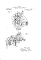
Fig. 2 is an elevation, parts shown in Fig. 1 being broken away;
Fig. 3 is a detail elevation at a right angle to Fig. 2 showing the internal yarnguide member cooperating with the splicing yarn finger;
Fig. 1 is a diagram in plan illustrating the relation of the needles, splicing yarn finger and the internal guide for the splicing yarn at the time of entrance of the splicing yarn;
Fig. 5 is a detail elevation of the yarn severing means;
Fig. 6 is a plan similar to Fig. 1 illustrating a modified operation of the devices;
and
Fig. 7 is an elevation partly in section on line 7-7 of Fig. 6.
As shown in Figs. 1 and 2, the machine may be provided above the bed-plate D for the knitting head, preferably as an attachment of the latch guard ring 550, with a bracket 1 having horizontal bearings for a short shaft 2 and a vertical bearing 8 for a center spindle 3 held in said bracket at the center of rotation of the needle-carrier or cylinder 260 for needles n, and serving if desired as a carriage for an instrument I dial 4, which may be driven, it so desired,
by shaft 3, bevel gears y and shaft Bracket 1 supports a cap or plate 5, which may if desired carry on its under surface cams for actuating the needles or other instruments mounted in dial 4. In some cases the dial may be above its actuating cap, and the plate 5 may then be any cover or support arranged to be held stationary with respect to the yarn-feeding means. Plate 5 carries on its upper surface gui(ling,.cla1n]')- ing and severing means for a series of ya-rns carried by movable yarn-guides preferably made as a series of yarn-fingers F to F pivoted on a stud in an extension 555 of latch guard ring These yarn fingers may be constructed and operated substantially as explained in my said Letters Patcut, one or more of them, such as F, being arranged and actuated to feed a splicingyarn :1; during the passage of a. predetermined segment of the needles n, for instance of substantially half of said needles. One means, as shown in said Letters Patent, for actuating such a yarn-guide for this purpose may comprise a cam rotating with a part attached to or moving in unison with the needle-carrier,' such as web-holder bed 295, Fig. 3, reacting with a lug on a thrustbar 460 to move the thrust-bar laterally against a lug s on the splicing yarn guide F to lift said guide to the position shown in dotted lines at 7 during each passage of the same part of the rotating circle of needles, thereby to throw yarn a: above and within the circle of needles. Splicing yarn a: will then be entered again during the same revolution by return of the yarnguide F to the full-line position, for instance by a spring f, when the rotating cam has passed.
The yarn-finger F and others of the series when rendered inoperative, so as to cease splicing, or to change the yarns, will be lifted to the position shown at 2, Fig.
Yarn-fingers at position 3 or position 2 will guide a yarn attached to the forming fabric near the needles, by the rotation of the needles in the direction of the arrow a,
'Fig. 1, above the plate 5, under a guide 0 on top of plate 5, and unless severed, the said yarn will then pass at an openin or other guide on the periphery of plate a to the underside of dial 4. An inclined guide 0 for causing the yarn to pass beneath the plate 5 and dial 1 may be provided as shown in Figs. 1 and The guide .7) may comprise.
tachment of a rin 9 arranged to form a smooth and rounded periphery for the dial 4 and plate 5. Ring 9 may be mounted on a stem 10 in a vertical bore in bracket 1,
and may be vertically movable to uncover the instrument-grooves of the dial; but for the purpose of guiding the yarn it will be understood that the ring 9 may be fixed, or dispensed with altogether as illustrated in Fig. 6, the edge of plate 5 being employed instead. Guide (3 or its equivalent may be mounted directly on or formed in plate 5, the function of the parts mentioned being to cause runs or floats of yarn thrown above the plate 5 when withdrawn from the necdles to pass to a position beneath plate 5 and dial 1 at the completion of a rotation or rotations, as shown at :0, Fig. 2. For this purpose, as when splicing yarn is lioated above plate 5, any instruments employed in dial 4 may if desired be withdrawn within its periphery at the segment swept by the yarn-float a or covered by ring 9, lowered during the splicing operation by hand or any practicable means.
I may provide a severing and clamping device for the splicing-yarn, when thrown out of work, and for the other yarns, for instance as shown in Figs. 1, 2 and 5, comprising a fixed shear-blade 12 mounted on bearing portion 8 of bracket 1 and a movable shear blade 13 pivoted at 14 on said portion 8, normally heldclosed by wire spring 15, and adapted to be operated by a lever 611 pivoted at 612 on the latch guard ring, for automatic operation by a pattern-controlled connection, for instance substantially as disclosed for operating the yarn-severing means in my said patent. \Vhenever one .of the yarns carried by. any of the yarn fingers, except the splicing yarn finger, is thrown above plate 5, the shears 12, 13, will be opened, and thereafter closed to sever the yarn. Whenever splicing is to cease, and
the splicing-yarn finger is thrown to positionv 2, the shears will be operated to sever .the splicing yarn.
released to sever For the purpose of clamping the severed ends of yarns thrown out of work, guide 6 may be actuated about its pivot 6 by spring 7 to hold a yarn passed under it. The clamp formed by guide I) and upper surface of plate 5 is conveniently opened automatically to release one .yarn and receive another by a pin 16 in lever 6 11 taking into a hole in guide or clamp b, so that whenever lever 611 is depressed to open the shears 12, 13, the clamp is opened, and whenever lever 611 is closed. e
The splicing-yarn a when being given to a section of the needles, takes against but does not enter the closed clamp-guide b upon its withdrawal at each revolution, neither sired place in the series of needles a to form the outgoing orwithdrawing border of the spliced area at a predetermined Wale of the fabric, but some uncertainty still exists under the best adjustments of the machine in g the entrance ofthe yarn m at the needles' Referring now to Figs. v and 4: it'will be observed that the rotation of the needles or instruments in the direction of arrow 0, will have swept the splieing-yarn'fioat about the periphery of theplate 5 until it encounters the guide a, theposition of the splicing-yarn guide now elevated topositiony being 'such as to cause the'tension of the yarn to drag it inward toward the center of the plate 5 and under the upturned part' of guide or clamp 12. Under-any arrangement dependout upon the position taken by such a float,
the motion of the needles draws off the yarn at the back of thegneedles at an angle to the needlessloping ,idthe direction of their travel, as illustratedbygthe position of the dotted line mfl Fig. 4,. Upon now attemptr ing to enter this yarn between a;pair of the yarn, the clamp is needles, it will be seen from inspection of Fig. 4 that the position of the yarn "lying at such an angle is unfavorable for entrance to. the space between adjacent needles. The yarn in the position v liesat an ,angle also 7'0 to the substantially radialfaiid downward path swept by the yarn feeding end/of the splicing yarn-fingenF whenimovi'ng to enter the yarnw, and its motion by suchinovement of the yarn-guide is not a downward swing. into the needles, as desired, but. is partly a lateral sweep against their backs. Ifthe yarn. m is left inthe position .71", it will eventually take between the needles when the yarn-finger F is dropped, but only after '80 being rubbed along their tops, and after the sl'ilicing yarn-guide has reached a position lower than that at which the yarn is sometimes capable of entering upon the needles.
I have therefore provided my machine '85 with. devices for-correcting the angle of the i floated yarn with respect to the line of needles prior to or during the'entrance of the splicing yarn at the needles for the p1-. rg pose of securing a favorable position for direct entrance of the yarn. Referring now to-Figs. 1 and 3, as one instance of means for this purpose Ihzwe illus trated a rocker-arn'i 21, held by collars 22, 7 23 on center spindle 3 for free rocking movement, for instance, as caused by a spring between said 7 arm '21 and any convenient fixed part, as bracket 1, and a cam 20 fast"; on shaft 2. A wire arm 27 adjustably held]? in a bore in rocker-arm 21 by set scre 28 extends downwardly and then outwardly above plate 5, terminating in a downwardly extending guide behind the needles aand i above the plane of instruments carriedby dial 4. An arc concentric with and behind 105. the needles is swept by guide 29,-which are extends from directly in'front of the active position of the splicing yarn finger F to a position outside of the line taken by the yarn a; when thrown above and within the needles. The position of cam 20 is such as to hold the guide 29 to the left, Figs. 1 and 4, during 3 passage of the withdrawn yarn :12, which by the stitching movement of the needles passes between the edge 9 ofth'e plate 5 and saidf guide, and u-nder the guide. lVhen the splicingyarn is to be entered, themost eccentric f part of cam 20 holds guide 29 in the position shown in Figs. 1 and 4, said guide having sweptthe yarn a: backward into ornear the 12o plane of moven'icnt of finger'F, and placed the yarn in a position to pass directly across the needles when the finger F drop v 1 W'hen yarn m is taken by the needles, the
.fioat :r of, said yarn is held down by' the 12?;
heedles to pass freely. between said guide and the edge 9 of plate 5. The figure of cam 20, as shown, may be such as to move rocker arm 21 and guide 29 backward to the position shown in dotted lines in Fig. lbefore 13o rotation of needles n causes the end entered at the needles of float m to pass its position.
Any convenient means for actuating rocker arm 21 may be employed, but I prefer the rotated shaft 2 and cam 20 as shown. Shaft 2 is conveniently driven by a bevel gear thereon meshing with a bevel g ona vertical shaft 33 passing through a hole in bed plate D and having a bearing in standard 31L, said shaft being driven by a bevel g on its lower end engaging a-bevel g on the hub of gear 31 on main drive shaft- 32, whereby the center spindle 3 is driven in unison with the needle-carrier for the needles n. I
One advantage of the indicated driving means is capacity for separation of gears g 9 when latch guard rin 550, bracket 1, and other attachments of said latch guard ring are lifted for access to the needles. Unless positively disturbed, a broken drive connection of this sort is restored upon replacing the part moved away without disturbance of the rotative adjustment of the part.
In some cases it is desirable to iioat the splicingyarn under the dial 4: without permitting the diametrical floats to pass above the cap 5, and as shown in Figs. 1, (3 and 7, I may accomplish this by use of an instrument I passing above the cylinder needles n at the place where they are withdrawn downwardly to knit, and beneath the dial, in cooperation with the depending arm 27, 29 or other positioning in ans for the splicing yarn. The instrument. 1, Figs. 6 and 7, may be a welt-presser employed at another time in the operation to cause fabric held on the instruments in the dial to pass downward beneath the dial, and I do not herein claim said instrument, except in combination with the means for positioning a withdrawn yarn, so that the yarn will enter the needles when intended to be inserted, said yarn being guided by instrument P beneath the dial. Said. instrument may be pivoted at p on an attachment of the standard for latch-ring 550, and may cooperate with a dial and a plate 5 having a ring 9 as shown in Fig. l or without such a ring, as shown in Figs. 6 and 7. Said instrument may be constructed in any convenient form, for instance as a thin spring metal body, terminating at p in a downwardly-bent cam-end adapted to pass over the needles and web-holders and under the plate 5 and dial a when actuated by a connection which may be a wire-link surrounded by a compression spring 79 and passed through a hole in the upright arm 71 of a rocker 7) free to swing on stud 472 in a mechanism. IVhenever splicing is to be done, the bar i is lifted by a suitable indication on the pattern surface controlling it to move the cam-end p of lever P inward as shown in Fig. 6.
A movable yarn-guide, such as splicing yarn finger F upon being lifted to position y, will then withdraw the yarn toward the backs of the needles, the relative motion sweeping the attached end of the yarn against the instrument P, around which the yarn will reeve as the relative travel of the fabric causes it to define an increasing chord of the circle of needles, the yarn pulling off from the elevated finger F to permit this passage beneath the dial and plate 5. So much of the yarn as extends between the splicing-yarn finger and the cam-end p of instrument P will rest in the space between the needles and the edge of plate 5, and against plate 5. At this time arm 27 is positioned near instrument P, but before the yarn is again entered, said arm 27 will move to bring its depending end 29 against the yarn between p and the bore in the yarnfinger, to move the yarn for entry substantially into the plane of movement of-finger F When the finger F is lifted to position a at the end of splicing, the shears 12, 13 and clamp b will be operated to sever and hold it above the plate 5, the instrument P being withdrawn prior to this time to permit the yarn to sweep around plate 5 and above it, as in the case of the yarns carried by the remaining yarn-fingers. The bar 11 may be controlled for this purpose by suitable cams on. the pattern surface controlling it for its usual functions.
\Vhen a yarn, for instance the splicing yarn, is guided beneath the dial by such an instrument as presser P, the space back of the needles need not be kept open to permit the 'arn to sweep the edge of the dial or other obstruction, except at the space between the place of exit of the yarn and the position of the guiding instrument, and the needles, transfer implements or other instruments may be projected at other parts of the circle. A floated yarn guided under the dial in the manner described is subjected to little or no strain, and less yarn is taken into the float than when it is thrown above the obstruction back of the needles.
The new inventions herein shown and described but not cl aimed are claimed in my copending applications Serial Nos. 66,424 and (36,425, filed December 13, 1915.
lVh-at I claim is:
1. A knitting machine having needles and a splicing yarn-feeding device operative during passage of a part only of said needles to feed a splicing yarn, whereby said yarn is floated behind the said needles, in combination with a plate supported within said needles, a guide for moving the floated yarn beneath said plate. and a-guide adapted to receive the floated ya-rn behind the needles, and actuating means for difi'erently positioning said last mentioned guide with referenee to the splicing yarn-feeding means to maintain the splicing yarn in position for guard, oscillating yarn guiding meansv mounted on said latch-guard and extending within the needles, a rotary cam and means tor rotating 1t mounted on said latch guard,
and means for actuating said yarn-guiding means from said cam.
4. A knitting machine having a dial, needles, and yarn-feeding means movable with respect tothe needles to .enter the yarn upon them, in combination with a movable guide to position the yarn for entry and a movable guide adapted to cause a withdrawn float of said yarn to lie beneath the dial.
5. A kn' ting machine having needles. a yarn-guide movablecrosswise of the needles to enter and remove its yarn, an instrument adapted to be moved across the needles to receive and guide the yarn down 'ard when it iswithdrawn, and a movable positioning device for the withdrawn yarn adapted to act on the yarn between said instrument and said yarn-guide. I
6. A'knittingmachine having a circular series of needles, a movable yarn-feed guide adapted to withdraw the yarn from the needles, in combination with a dial, means to position the withdrawn yarn for reentry, and meansto guide the withdrawn yarn under the dial acting at a point near the place oi action of said yarn-feed guide.
7. A knitting machine having needles, a.
dial, and means movable crosswise of the needles to enter a yarn at the needles, in combination With means movable behind the needles to position the yarn for entry, and an instrument movable over the needles to guide the yarn under the dial when it is Withdrawn.
8. A knitting machine having a circle of needles, a movable yarn-guide, a dial and a plate obstructing substantially all the space within the needles, a movable yarn guide, an instrument adapted to guide a yarn withdrawn by said yarn-guide under said.
obstru ons, and means above said obstructions t receive and position a part of the yarn fol reentry.
9. Sectional ""splicing means-adapted for cooperation with circular knitting machines having an instrument-dell 'con'iprising in con'ibination, a splicing-yarn guide and means to actuate it to withdraw a yarn above the needles at times related to the passage of a segment of the needles; a plate above said dial mounted substantially concentric with the needles whereby a yarn witlulrawn passes above said plate, a depending arm mounted to move between said plate and the needles, and means to move said arm to encounter and move the yarn into position for entrance at the needles between successive actuations of said splicing-yarn guide.
10. Yarn-feeding means for a circular knitting machine having needles and an instrument dial comprising said dial, a plate above said dial, movable yarn-teeding'yarn guides, and yarn guiding means on said plate, in combination with means on said plate for guarding a yarn sweeping the periphery of said plate from contact with the edge'of said dial or instruments carried thereby.
11. An internal yarn-guiding device for knitting machines having a circle of needles, and a dial within said needles, comprising a plate above and covering said dial, and a ring at the periphery thereof adapted to guide a yarn withdrawn from the fabric at said needles and passed above said plate.
12. An internal yarn-guiding device for knitting machines having a circle of needles and a dial within said needles comprising a, plate above and covering said dial, and a yarn-guarding ring at the periphery of. said plate mounted for movement thereon to cover or uncover the verge of said dial.
Signed -by me at Boston, Massachusetts, this tenth day of December, 1915.
, ROBERT W. SCOTT.
Priority Applications (1)
| Application Number | Priority Date | Filing Date | Title |
|---|---|---|---|
| US6642615A US1237256A (en) | 1915-12-13 | 1915-12-13 | Yarn-feeding device for knitting-machines. |
Applications Claiming Priority (1)
| Application Number | Priority Date | Filing Date | Title |
|---|---|---|---|
| US6642615A US1237256A (en) | 1915-12-13 | 1915-12-13 | Yarn-feeding device for knitting-machines. |
Publications (1)
| Publication Number | Publication Date |
|---|---|
| US1237256A true US1237256A (en) | 1917-08-14 |
Family
ID=3305075
Family Applications (1)
| Application Number | Title | Priority Date | Filing Date |
|---|---|---|---|
| US6642615A Expired - Lifetime US1237256A (en) | 1915-12-13 | 1915-12-13 | Yarn-feeding device for knitting-machines. |
Country Status (1)
| Country | Link |
|---|---|
| US (1) | US1237256A (en) |
Cited By (3)
| Publication number | Priority date | Publication date | Assignee | Title |
|---|---|---|---|---|
| US3077097A (en) * | 1956-12-06 | 1963-02-12 | Gordon Company | Yarn handling and severing mechanism for circular knitting machines and methods |
| US3097513A (en) * | 1963-07-16 | Yarn cutting and clamping means for knitting machines | ||
| US3252307A (en) * | 1963-02-15 | 1966-05-24 | Textile Machine Works | Yarn severing means for knitting machines |
-
1915
- 1915-12-13 US US6642615A patent/US1237256A/en not_active Expired - Lifetime
Cited By (3)
| Publication number | Priority date | Publication date | Assignee | Title |
|---|---|---|---|---|
| US3097513A (en) * | 1963-07-16 | Yarn cutting and clamping means for knitting machines | ||
| US3077097A (en) * | 1956-12-06 | 1963-02-12 | Gordon Company | Yarn handling and severing mechanism for circular knitting machines and methods |
| US3252307A (en) * | 1963-02-15 | 1966-05-24 | Textile Machine Works | Yarn severing means for knitting machines |
Similar Documents
| Publication | Publication Date | Title |
|---|---|---|
| US3232079A (en) | Circular knitting machine | |
| US1237256A (en) | Yarn-feeding device for knitting-machines. | |
| US1115128A (en) | Knitting-machine. | |
| US3174307A (en) | Thread changing apparatus | |
| US2302946A (en) | Circular knitting machine of the axially opposed needle cylinder type | |
| US2959040A (en) | Circular knitting machines of the superimposed needle cylinder type | |
| US1256062A (en) | Yarn-feeding device for knitting-machines. | |
| US3367146A (en) | Elastic yarn tensioning and clamping mechanism for knitting machines | |
| US1150547A (en) | Mechanism for knitting upon-transferred fabric sections. | |
| US1990416A (en) | Knitting machine | |
| US1214828A (en) | High-splicing mechanism for circular-knitting machines. | |
| US1105735A (en) | Circular french-welt knitting-machine. | |
| US2045459A (en) | Two-color lap stripe mechanism | |
| US1238052A (en) | Yarn-feeding mechanism for knitting-machines. | |
| US1191937A (en) | Sinker-wheel mechanism. | |
| US2000798A (en) | Circular knitting machine | |
| US2126646A (en) | Cam for knitting machines | |
| US1373676A (en) | Yarn feeding and severing mechanism for knitting-machines | |
| US460502A (en) | davis | |
| US1775333A (en) | Yarn-feeding device for knitting machines | |
| US1159873A (en) | Yarn feeding and changing mechanism for knitting-machines. | |
| US1652500A (en) | Dial-positioning and yarn-feeding mechanism eos dial knitting machines | |
| US1984656A (en) | Circular knitting machine | |
| US670392A (en) | Thread-changing mechanism for knitting-machines. | |
| US1891215A (en) | Circular knitting machine |