US1237235A - Molding-flask. - Google Patents
Molding-flask. Download PDFInfo
- Publication number
- US1237235A US1237235A US10160916A US10160916A US1237235A US 1237235 A US1237235 A US 1237235A US 10160916 A US10160916 A US 10160916A US 10160916 A US10160916 A US 10160916A US 1237235 A US1237235 A US 1237235A
- Authority
- US
- United States
- Prior art keywords
- section
- flask
- strips
- drag
- walls
- Prior art date
- Legal status (The legal status is an assumption and is not a legal conclusion. Google has not performed a legal analysis and makes no representation as to the accuracy of the status listed.)
- Expired - Lifetime
Links
Images
Classifications
-
- B—PERFORMING OPERATIONS; TRANSPORTING
- B22—CASTING; POWDER METALLURGY
- B22C—FOUNDRY MOULDING
- B22C21/00—Flasks; Accessories therefor
Definitions
- My invention relates to molding flasks of the class provided with sand strips and the objects of my improvements are to provide means whereby afpattern frame may or'may not be used as desired Without changing the relative verticalposition of the flask sections or changing the quantity of, sand required for the mold and which will also prevent any ofiset in the plane of the walls of the mold at its parting line, that the jacket may be easily and snugly placed in position thereon; to provide automatic means for preventing the drag section from being forced in a downward direction on the drag cake by means of pressure exerted on the cope section thereon, that the parting surface of the drag cake may be maintained flush with the top of the drag, section; to
- Figure 1 is a plan with parts broken away of a molding flask embodying my improvements
- Fig. 2 an inverted plan with parts broken away of the cope section with the sand strips
- Figs. 3 and 4 isometrical views of a corner portion of the cope section, showing the adjustable lever mechanism for actuating the adj acent sand strips
- Figs.' isometrical views of a corner portion of the cope section, showing the adjustable lever mechanism for actuating the adj acent sand strips
- 1 represents the drag section of a molding flask formed with downwardly divergent end and side walls 2 and 3 and provided with the usual flask pins 4.
- the lower inside portion of its end for resisting any downward movement of the drag section from pressure of the cope section thereon and for maintaining the parting surface of the mold in fixed relation to the parting edge of the flask.
- top' outside portion of the walls of said drag I section are formed with a rabbet or recess 8 wherein a pattern frame 9 may be sup-' ported preferably flush with the top of said a section.
- Said pattern frame is provided with lifting ears 10 and with oppositely disposed-lugs 1.1 which are extended within the flask through opengaps (not shown) formed injthe parting edge of the flask and i '-to which the gated patterns 12 may be secured at 13 as by soldering.
- the cope section 14 1 rigidly formed-with- Jdownwardly divergent end and side walls '15 and l6to register' with the correspondingywall'sbf the drag section and provided on its ends with pairs, of outwardly projectingf'stud's "17* whereon the lifting cars 18 ing engagement with the'flask pins by means of the adjusting nuts 19 and similar lifting ears adjustably secured in like manner'on' the cope section by means of the lips 26 .being extended a short distance under their end portions.
- the ends of all the sand strips and the oblique slots therein are parallel with lines drawn at an angle of forty five degrees to the direction of the length of the flask.
- Beds 27 adjustably secured to the bosses 23 of adjacent end and side sand strips by means of the adjusting nuts 28 are formed with intermediate bends and terminate in alinement outside of the corresponding opposite corners 29 and 31 of the oopesection.
- Legs 32 hinged on said respective opposite corners of the cope section depend therefrom and each terminates in an open slot 33 in movable engagement with the end portion of the adjacent rods 27:
- Crank arms 34 secured to the respective legs are extended parallel with the adjacent end walls of the cope sectionand terminate near the corresponding lifting ears thereon. Said arms serve to move the legs and the rods 27' with the .s'and strips in parallel oblique direc-.
- the lateral inclination of the sand strips avoids the interference of theloose sand with their movement, prevents them from parting surface of the drag,
- the bottom board may be forced partially therein under the exertion of a molding machine or otherwise to the extent limited only by the greater resistance of the end portions of. the 'dragcake against the shoulders formed onthe end Walls.
- the excessively packed end portions of the drag cake serves to form steps to prevent the drag section from being pressed in adownwarfl direction by the cope member when sup orted thereon, that its relative position to t may be maintained.
- the walls of the mold will remain in the same inclined planes and without any offset at the parting line whether a pattern supporting frame has been employed or not that the usual jacket may be easily and snugly fitted around the mold for covering the parting line thereof.
- the relative position of the sand strips and the limit of their movement maybe accurately adjusted by means of the nuts on the rods connected therewith, and
- a molding flask section provided with sand strips, and actuating lever mechanism supported thereon and adjustably secured to said strips.
- a molding flask section having its part i ing edge formed on the outside with a rabbetwherein a pattern frame may be supported, .and having portions of the opposite edge of said section formed on the inside with a rabbet for the insertion of a bottom board therein for the purpose specified.
- a molding sand strips supported under'its respective walls and movable at oblique angles in down- Wardly convergent planes, and actuating.
- “flask section rigidly conflask section comprisingconnections supported adjustably secured to on opposite portions of said section is o structed and in form the frustun'i of a pyramid, sand strips supported under 1ts respective Walls and inovable at oblique angles in downwardly convergent planes, and actuating lever connections supported on opposite corners of saidsection and adjust-ably secured to the respective strips adjacent thereto.
- a molding flask comprising a cope sec tion rectangular in form, sand strips supported under its respective walls-and movable in pairs at an oblique angle and in downwardly convergent planes, and actuating lever connections supported on respective opposite portions otsaid section and adjustably secured to the respective strips of the said pairs adjacent thereto.
- a molding flask section rigidly constructed and in form the frustum of a pyramid, sand strips supported under its respective walls and movable in pairs in opposite directions at an angle to the length of said section, and actuating connections supported on said section and adjust-ably secured to the respective strips of the pair ofstri'ps adjacent thereto.
- a molding flask comprising a drag section rectangular in form and having slanting'walls formed with an inside portion of their thickness extended above the outside portion thereof to form a thin parting edge adapted to be inserted through a pattern frame.
- a molding flask comprising a drag section having its walls formed with an upward'extension of the inside portion of their thickness to form a thin parting edge, and with a downward extension of the outside portion beyond the inside portion of Certain of its walls to rovide a recess on theinside surface thereoi wherein projections may be formed on the drag cake, for the purpose specified.
- a molding flask section having its Walls formed with a rabbet around the outside of its parting edge to receivefa pattern frame.
- a molding flask section having the inner portion of the parting edge of its walls extended beyond the outer portion thereof for projecting within a pattern frame.
- a molding flask comprising a drag section'having its walls constructed and arranged with a ledge for supporting a pattern frame flush with its top surface.
- a molding flask section inform the frustum of a pyramid,having the parting edge of its Walls formed with a rabbet in their outside surface, and the'opposite edges of certain of said walls being formed with a rabbet in the inside surface.
- a molding flask comprising a cope section, sand strips supported thereunder and movabis in downwardly convergent planes, and "lever mechanism-for actuating said strips.
- a molding flask comprising a rigidly.
- a molding flask comprising a rectaa gular cope section, sand strips supported under its respective walls and movable in down' Wardly convergent planes, and separate lever mechanism supported on opposite corners of said'section for actuating the strips adjacent thereto.
- a molding flask comprising a cope section, sand strips secured thereunder and movable in planes inclined at an angle to the horizontal plane of said section, and lover mechanism secured to said section for actuating said strips.
- QL-A molding flask comprising a plurality of coiiperating sections, pins secured on one of said, sections, pairs of threaded studs projecting adjacent thereto from one of the other said sections, lifting ears on the respective pairs of studs, and adjustable units on the studs for maintalning the ears thereon in proper (1181531166 relations to the associated section and also in oro .l.
- a molding flask comprising a rigidly constructed drag section in form the trustum of a pyramid,.having the lower edge of certain of its walls recessed on the inside,
- a molding flask comprising a drag of the bottom board therein, for the purpose section formed with an inclined wall having specified. l 3 the outside portion of its lower edge formed FRANKJ. BECKER I with an extension beyond the inside portion thereof to provide a recess wherein a step Witnesses: Y may be formed on the contiguous wall of the GEORGE 115. DANA, drag cake by the moyement under pressure R. SJCAKR.”
Description
F. J. BECKER.
MDLDING F'LASK.
APPLICATION F ILED JUNE 3. ms.
Patented Aug. 14, 1917.
\Mnass is,
,9, ma 51W.
r crimp rnAnK J. BECKER, or 'HAMI'Lron, 01110.
MOLDING-FLASK.
Application filed June 3, 1918. Serial No. 101,609.
To all whom it may concern:
Be it known that I, FRANK J. BECKER, a citizen of the United States, residing at Hamilton, Ohio, have invented a new and useful Improvement in' Molding-Flasks, oi which the following is a specification.
My invention relates to molding flasks of the class provided with sand strips and the objects of my improvements are to provide means whereby afpattern frame may or'may not be used as desired Without changing the relative verticalposition of the flask sections or changing the quantity of, sand required for the mold and which will also prevent any ofiset in the plane of the walls of the mold at its parting line, that the jacket may be easily and snugly placed in position thereon; to provide automatic means for preventing the drag section from being forced in a downward direction on the drag cake by means of pressure exerted on the cope section thereon, that the parting surface of the drag cake may be maintained flush with the top of the drag, section; to
,provide' means for limiting the depth to which the bottom board maybe forced within the drag section under the predetermined pressure thereon, as by a molding machine; to provide adjustable lever mechanism for actuating the sand strips in downwardly convergent planes to avoid breaking the ad'- termined distance relation for securing accurate registration of the. flasksections by} the sliding engagement'of said ears-with the flask pins,.an d to provide rigid and durable construction and assemblage :ofthe various' members for securing accuracy, facility 0 v may-"be'adjustablysecured in accurate slidjacentparting surface of the drag cake, to prevent the loose sand from interfering with their movement and to form a beveled edge on the cope cake for making it less easily broken and'more eflic'ient for lifting said cake by means of the sand strips thereunder-ato provide means for adjustably securing the sand. strips in proper relation to each other to be'moved a uniform distance within the flask; to provide means for adjustably securing the'lifting ears in predeoperation and efiiciency of actlon.
These objects together ,wi
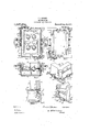
incorporated inrthe claims may be attained in the following described manner as illus-" h others to trated in the accompanying drawings, in which l Figure 1 is a plan with parts broken away of a molding flask embodying my improvements;'Fig. 2 an inverted plan with parts broken away of the cope section with the sand strips; Figs. 3 and 4 isometrical views of a corner portion of the cope section, showing the adjustable lever mechanism for actuating the adj acent sand strips, and Figs.'
5 and 6 vertical sections with parts broken away on the respective lines aa and b-b of Fig. 1. I p
In the drawings, 1 represents the drag section of a molding flask formed with downwardly divergent end and side walls 2 and 3 and provided with the usual flask pins 4. The lower inside portion of its end for resisting any downward movement of the drag section from pressure of the cope section thereon and for maintaining the parting surface of the mold in fixed relation to the parting edge of the flask. The
top' outside portion of the walls of said drag I section are formed with a rabbet or recess 8 wherein a pattern frame 9 may be sup-' ported preferably flush with the top of said a section. Said pattern frame is provided with lifting ears 10 and with oppositely disposed-lugs 1.1 which are extended within the flask through opengaps (not shown) formed injthe parting edge of the flask and i '-to which the gated patterns 12 may be secured at 13 as by soldering.
The cope section 14 1s rigidly formed-with- Jdownwardly divergent end and side walls '15 and l6to register' with the correspondingywall'sbf the drag section and provided on its ends with pairs, of outwardly projectingf'stud's "17* whereon the lifting cars 18 ing engagement with the'flask pins by means of the adjusting nuts 19 and similar lifting ears adjustably secured in like manner'on' the cope section by means of the lips 26 .being extended a short distance under their end portions. The ends of all the sand strips and the oblique slots therein are parallel with lines drawn at an angle of forty five degrees to the direction of the length of the flask.
tions a predetermined distance within the flask for lifting the cope cake by means of the cope section.
The lateral inclination of the sand strips avoids the interference of theloose sand with their movement, prevents them from parting surface of the drag,
disturbing the cake and forms a beveled edge on the cope cake which permits it to be replaced in accurate position on the drag cake and is less liable to crumble when the jacket is being placed in position on the mold.
In operation, the drag section being placed in inverted position on the match with the patterns and filled with sand, the bottom board may be forced partially therein under the exertion of a molding machine or otherwise to the extent limited only by the greater resistance of the end portions of. the 'dragcake against the shoulders formed onthe end Walls. The excessively packed end portions of the drag cake serves to form steps to prevent the drag section from being pressed in adownwarfl direction by the cope member when sup orted thereon, that its relative position to t may be maintained. After turning the drag section with the drag cake to rest on the bottom board and the cope section is placed thereon, the sand strips may be moved with their inside edges close to the parting sure parting line.
neat/pee face of the drag cake and thecopecake completed in the usual manner. Said strips serve to lift the cope cake from'the drag cake and after the removal to return it in accurate. position thereon, When they may-be returned beyond the walls of the mold for the removal of both the cope and drag members therefrom in the usual manner.
After the removal of the flask the walls of the mold will remain in the same inclined planes and without any offset at the parting line whether a pattern supporting frame has been employed or not that the usual jacket may be easily and snugly fitted around the mold for covering the parting line thereof. The relative position of the sand strips and the limit of their movement maybe accurately adjusted by means of the nuts on the rods connected therewith, and
proper adjustment of the together with the lifting ears on similar ears on tion to the flask pins, precision and accuracy may be secured and maintained in the operation of the flask for producing castings the cope section and also of of the patterns,
the pattern. frame in relaw of perfect form and true to the patterns used.
Having fully described my improvements, what I claim as my inventionand desire to secure by Letters Patent of the United States is .1. A molding flask section provided with sand strips, and actuating lever mechanism supported thereon and adjustably secured to said strips.
2. A molding flask section having its part i ing edge formed on the outside with a rabbetwherein a pattern frame may be supported, .and having portions of the opposite edge of said section formed on the inside with a rabbet for the insertion of a bottom board therein for the purpose specified.
3. A molding sand strips supported under'its respective walls and movable at oblique angles in down- Wardly convergent planes, and actuating.
connections therewith supported on said section.
4. A molding flask section rectangular in form having sand strips supported under its respective walls, said strips being movable at oblique angles in downwardly convergent planes, and actuati on said section an said strips. I
5. A molding flask section in form the frustum of a pyramid, sand strips supported,
under its respective walls and movable at oblique angles in downwardly convergent planes, and actuating lever mechanisms supported and adjustably secured to the strips adjacent thereto.
6. "flask section rigidly conflask section comprisingconnections supported adjustably secured to on opposite portions of said section is o structed and in form the frustun'i of a pyramid, sand strips supported under 1ts respective Walls and inovable at oblique angles in downwardly convergent planes, and actuating lever connections supported on opposite corners of saidsection and adjust-ably secured to the respective strips adjacent thereto. v
7 A molding flask comprising a cope sec tion rectangular in form, sand strips supported under its respective walls-and movable in pairs at an oblique angle and in downwardly convergent planes, and actuating lever connections supported on respective opposite portions otsaid section and adjustably secured to the respective strips of the said pairs adjacent thereto.
8. A molding flask section rigidly constructed and in form the frustum of a pyramid, sand strips supported under its respective walls and movable in pairs in opposite directions at an angle to the length of said section, and actuating connections supported on said section and adjust-ably secured to the respective strips of the pair ofstri'ps adjacent thereto.
9. A molding flask comprising a drag section rectangular in form and having slanting'walls formed with an inside portion of their thickness extended above the outside portion thereof to form a thin parting edge adapted to be inserted through a pattern frame. v
10. A molding flask comprising a drag section having its walls formed with an upward'extension of the inside portion of their thickness to form a thin parting edge, and with a downward extension of the outside portion beyond the inside portion of Certain of its walls to rovide a recess on theinside surface thereoi wherein projections may be formed on the drag cake, for the purpose specified.
11. A molding flask section having its Walls formed with a rabbet around the outside of its parting edge to receivefa pattern frame.
12. A molding flask section having the inner portion of the parting edge of its walls extended beyond the outer portion thereof for projecting within a pattern frame.
13. A molding flask comprising a drag section'having its walls constructed and arranged with a ledge for supporting a pattern frame flush with its top surface.
14. A molding flask section inform the frustum of a pyramid,having the parting edge of its Walls formed with a rabbet in their outside surface, and the'opposite edges of certain of said walls being formed with a rabbet in the inside surface.
15. A molding flask comprising a cope section, sand strips supported thereunder and movabis in downwardly convergent planes, and "lever mechanism-for actuating said strips.
16. A molding flask comprising a rigidly.
constructed cope section having downwardly divergent walls, sand strips supported under the respective walls, and adjustable lever walls, and actuating lever mechanism ad- I justably secured to the strips.
1.8. In a molding flask the combination with a rectangular cope section, of sand strips supported under its respective Walls, and actuating means therefor supported-on opposite corners of said section and adjustably connected to the strips adjacent thereto. 19. A molding flask comprising a rectaa gular cope section, sand strips supported under its respective walls and movable in down' Wardly convergent planes, and separate lever mechanism supported on opposite corners of said'section for actuating the strips adjacent thereto.
' 20. A molding flask comprising a cope section, sand strips secured thereunder and movable in planes inclined at an angle to the horizontal plane of said section, and lover mechanism secured to said section for actuating said strips.
QL-A molding flask comprising a plurality of coiiperating sections, pins secured on one of said, sections, pairs of threaded studs projecting adjacent thereto from one of the other said sections, lifting ears on the respective pairs of studs, and adusting units on the studs for maintalning the ears thereon in proper (1181531166 relations to the associated section and also in oro .l.
section rectangular in form and having the lower'edge of its opposite walls formed on the insidewith a rabbet, and a bottom board adapted to be removably inserted therein.
25. A molding flask comprising a rigidly constructed drag section in form the trustum of a pyramid,.having the lower edge of certain of its walls recessed on the inside,
and a bottom board movable within said recessed portion of the section and Whereon the mold cake may-be supported.
26. A molding flask comprising a drag of the bottom board therein, for the purpose section formed with an inclined wall having specified. l 3 the outside portion of its lower edge formed FRANKJ. BECKER I with an extension beyond the inside portion thereof to provide a recess wherein a step Witnesses: Y may be formed on the contiguous wall of the GEORGE 115. DANA, drag cake by the moyement under pressure R. SJCAKR."
Priority Applications (1)
| Application Number | Priority Date | Filing Date | Title |
|---|---|---|---|
| US10160916A US1237235A (en) | 1916-06-03 | 1916-06-03 | Molding-flask. |
Applications Claiming Priority (1)
| Application Number | Priority Date | Filing Date | Title |
|---|---|---|---|
| US10160916A US1237235A (en) | 1916-06-03 | 1916-06-03 | Molding-flask. |
Publications (1)
| Publication Number | Publication Date |
|---|---|
| US1237235A true US1237235A (en) | 1917-08-14 |
Family
ID=3305053
Family Applications (1)
| Application Number | Title | Priority Date | Filing Date |
|---|---|---|---|
| US10160916A Expired - Lifetime US1237235A (en) | 1916-06-03 | 1916-06-03 | Molding-flask. |
Country Status (1)
| Country | Link |
|---|---|
| US (1) | US1237235A (en) |
-
1916
- 1916-06-03 US US10160916A patent/US1237235A/en not_active Expired - Lifetime
Similar Documents
| Publication | Publication Date | Title |
|---|---|---|
| US1237235A (en) | Molding-flask. | |
| US9095A (en) | Improvement in patterns for metal hubs | |
| US177395A (en) | Improvement in molder s flasks | |
| US1055479A (en) | Molding-machine. | |
| US1288326A (en) | Mold-jacket and method of making the same. | |
| US1113739A (en) | Means for movably supporting patterns. | |
| US560404A (en) | Molding-machine | |
| US981489A (en) | Sad-iron pattern. | |
| US1029079A (en) | Molding-machine. | |
| US1024512A (en) | Type-mold. | |
| US55504A (en) | Improved apparatus for molding castings | |
| US1537299A (en) | Jacket for sand molds | |
| US1386104A (en) | Molding-machine | |
| US856383A (en) | Building-block machine. | |
| US928786A (en) | Molding-machine. | |
| US453373A (en) | And lazard kahn | |
| US981898A (en) | Mold-pattern for stove-lids. | |
| US1708568A (en) | Pattern | |
| US239302A (en) | jaevis adams | |
| US781961A (en) | Molding-machine. | |
| US380300A (en) | William sykes and squire sykes | |
| US865071A (en) | Molding-machine. | |
| US720690A (en) | Mold-forming machine. | |
| US161784A (en) | Isviprovesviemt in moldlng-iv achines | |
| US220086A (en) | Improvement in chills for chilling mold-boards for plows |